1
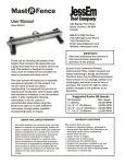
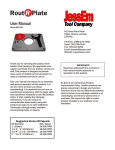
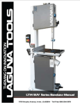
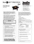
Mite R Excel
27186
Precision Miter Gauge
with Dual Indexing Angle Location
User Manual
Model #07100
124 Big Bay Point Road
Barrie, Ontario, L4N 9B4
Canada
866-272-7492 Toll Free
705-726-6145 Local Phone
705-726-6055 Fax
Email: [email protected]
Website: www.jessem.com
Thank you for choosing this product from
JessEm Tool Company. We appreciate your
support and hope that our product serves you
well. This product is designed to provide
many years of reliable service provided it is
used as intended and taken care of.
This user manual will assist you in assembly
and general operation of this product. It is
not our intent to teach you about
woodworking. It is assumed that you are an
experienced woodworker with the basic skills
and experience necessary to use this product
safely. If you are unsure or uncomfortable
about safely using this product after reading
the following instructions we urge you to seek
additional information through widely
available woodworking books or classes.
As part of our Continuous Product
Improvement Policy, JessEm products are
always advancing in design and function.
Therefore there may be differences between
what is shown in our catalogs, website or at
retail display and what is sold at time of
purchase. We reserve the right to make
positive changes to our products at our
discretion without notification.
IMPORTANT!
Read and understand the contents of
this manual before assembly or
operation of this product.
IMPORTANT!
Make sure that no part of the miter
gauge or fence can make contact with
the blade or cutter and all knobs are
securely tightened before each use.
MITER GAUGE COMPONENTS
The diagram below shows key components
for using this miter gauge.
SCALE
FENCE EXTENSION LOCKING
CLAMPING KNOB DIAL
FENCE EXTENSION
SCALE INDICATOR
GAUGE
CLAMPING
HANDLE
FENCE
CLAMP
KNOB
PIN
STORAGE
SMALL
LOCATOR
PIN
LARGE
LOCATOR
PIN
RTD10000137AA
IMPORTANT SAFETY PRECAUTIONS
! Before operating any machinery, power
tool or accessory read and understand all
safety instructions in the owner’s manual
for the tool, machine or accessory in use.
! If you do not have a manual, contact the
manufacturer and obtain one before
using any tool or equipment.
! Always wear proper eye protection that is
in compliance with ANSI safety standards
when operating any power tool or
machinery.
! Always use proper guards and safety
devices when operating power tools and
machinery.
! Carefully check accessories or other
equipment before each use. Do not use if
damage or defect is suspected.
! Do not wear loose clothing or jewelry that
may catch on tools, machinery,
accessories or other equipment.
! Always make sure the fence, gauge and
all adjustable knobs are locked firmly
into a tight position before each use.
! Before making any cut, always be sure
the miter gauge fence or any other part of
this accessory or other accessories used
with this product offer a safe clearance
and will not make contact with the saw
blade or any other cutting source.
FENCE CLAMPING
KNOBS
FIG. 2
ATTACHING THE FENCE
2. Loosen the two brass fence clamping
knobs. Take the miter fence and slide the
fence mounting bar into the center track on
the fence back. Then re-tighten the two brass
fence clamping knobs to secure the fence
into position on the mounting bar. (Fig. 2)
FENCE EXTENSION
CLAMPING KNOB
FIG. 3
ATTACHING THE FENCE EXTENSION
3. Assemble the fence extension to the
main fence by sliding the extension bar into
the center track in the back side of the main
fence extrusion. Tighten the brass fence
extension clamping knob to secure the
extension to the main fence. (Fig. 3).
BRASS
WASHER
FIG. 1
ATTACHING THE LARGE CLAMPING HANDLE
1. Remove the hex nut from the threaded stud
on the gauge clamping handle. Discard the nut
as it only secures the brass washer during
shipping and is no longer needed. With the
brass washer over the stud on the miter gauge
clamping handle, turn the handle with stud
through the washer and into the tapped hole in
the indexing plate and lightly tighten (Fig. 1).
FIG. 4
ATTACHING THE FENCE STOP
4. Now attach the fence stop to the fence by
sliding the square nut into the track along
the top of the main fence. (Fig. 4).
FIG. 8
FIG. 5
5. The fence stop should look like this when
properly mounted on the main fence. (Fig. 5).
2”
POSITION FENCE
AT LEAST
1/16” FROM
SAW BLADE
SLIDE FENCE EXTENSION
SCALE INDICATOR TO (26”)
SAW BLADE
SET STOP 2” FROM
CUTTING EDGE OF BLADE
8. Loosen the ¼” socket head screw that
attaches to the slide bar on the fence
extension block (Fig. 8).
LOOSEN FENCE
EXTENSION
LOCKING KNOB
FIG. 6
SETTING THE SCALES ON THE FENCE
6. Place the miter gauge in the miter slot in
your table saw with the saw turned off.
Loosen the two brass fence clamping knobs
(shown in fig. 2) and slide to adjust the miter
fence so it is clearing the saw blade teeth by
at least 1/16 of an inch. Re-tighten the
fence clamping knobs. Then position the
fence flip stop so it is set 2 inches in from
the cutting edge of the saw blade. Tighten
the flip stop in position.
9. Loosen the fence extension locking knob.
Adjust the fence extension bar so the right
side of the fence extension scale indicator
lines up with the 26 inch mark on the fence
scale. Re-tighten the fence extension locking
knob (Fig. 9).
SET STOP 26” FROM BLADE
SCALE
LOCKING KNOB
FIG. 7
7. Loosen the fence scale locking dial (Fig. 7)
and adjust the sliding scale so the left edge of
the indicator lines up with the 2 inch mark on
the scale (Fig. 6). Then re-tighten the fence
scale locking dial.
FIG. 9
FIG. 10
10. Slide the fence extension block all the way
in toward the main fence so it is tight against
the main fence (Fig. 10). Re-tighten the ¼”
socket head screw as shown in fig. 8. Slide the
fence stop onto the fence extension (Fig. 10)
and with a tape measure or steel rule set the
fence stop 26 inches from the cutting edge of
the blade and lock it in this position. Then
loosen the scale locking knob on the fence
extension and adjust the short scale so the left
side of the scale indicator lines up with the 26
inch line marked “STOP POSITION” (Fig. 10).
The scale for the fence extension is now set.
LARGE
LOCATOR
PIN
SMALL
LOCATOR
PIN
ANGLE
SCALE
FIG. 11
FITTING THE BAR IN THE MITER SLOT
11. The bar on the miter gauge has two hex key
adjustment locations to remove any side to side
slop in the miter slot. Adjusting the fit can be
done easily from above the table. Turn the hex
key clockwise to tighten and counter clockwise
to loosen. Alternate between the two hex key
locations and make only slight adjustments
while testing the movement of the gauge in the
track (Fig. 11).
HOLE
FOR PIN
STORAGE
USING THE .5, 1, 1.5, & 2 DEGREE LOCATORS
13. The numbered peg holes on the left and
right side are used to offset the gauge by .5, 1,
1.5, 2, and 2.5 degrees from every five degrees
on the angle scale. Using the small locator pin in
the holes on the left will give you that number of
degrees left of every five degrees. Using the pin
holes on the right will give you that number of
degrees to the right of every five degrees. For
example, placing the small locator pin in the (1)
degree hole on the left gives you (1) degree left
of every 5 degrees. Placing the small locator pin
in the (1) degree hole on the right gives you (1)
degree to the right of every five degrees. Fig. 13
shows the small peg in the 1 degree hole on the
left side. This offsets the gauge by 1 degree
increments to the left of every five degrees as
you rotate the fence and use the large locator
pin to lock in the actual position. The gauge is
shown at 6 degrees in Fig. 13. (1) degree left of
5 degrees.
LARGE
LOCATOR
PIN
SMALL
LOCATOR
PIN
USING THE DUAL INDEXING ANGLE LOCATING
Attached to the gauge face are two brass
locator pins, a large and a small. These pins
are used together to achieve any angle location
down to ½ degrees. The following instructions
explain how the dual indexing system works.
SMALL
LOCATOR
PIN
FIG. 13
FIG. 12
Note: Always loosen the gauge clamping handle
on the miter gauge face before pulling any
locator pins. Then tighten the clamping handle
after your desired position is achieved.
SETTING AT ZERO & EVERY FIVE DEGREES
12. To position the gauge at 90 degrees, place
the small locator pin in the hole marked “0”, just
left of center. Place the large locator pin in the
center hole (above the zero on the angle scale).
The large locator pin can now also be used to
locate positive stops at every five degrees left or
right on the scale. Simply pull out the large
locator pin and angle the fence to move the
gauge in any five degree increment and then
push the pin into your desired position (Fig. 12).
LARGE
LOCATOR
PIN
FIG. 14
USING THE 2.5 DEGREE SETTING
14. There is only one 2.5 degree pin location. It
is the hole on the far right side of the gauge.
Placing the small locator pin in the 2.5 degree
position and then using the large locator pin to
give you positive stops between every five
degrees in either the left or right direction.
A setting for 22.5 degrees is shown in Fig. 14.
To use the gauge in a normal or manual miter
gauge mode put the large locator pin in the pin
storage hole (see Fig. 12).
INSTRUCTIONS FOR
SQUARING THE MITER GAUGE FACE
SUPPLEMENT TO MODEL 07100 MANUAL
There are several variables which can effect the
squareness of cut with any miter gauge. The table
saw’s arbor, the saw blade, the miter slot in the table
saw top, the miter gauge fence and it’s relationship
to the guide bar under the miter gauge and including
the parts used to connect these components to their
axis. The Mite-R-Excel miter gauge should be square
out of the box. However, if after making test cuts, you
find the results are not square, the miter gauge face
can be adjusted as needed.
1. There are two tapped holes on the fence
mounting plate (Fig. 3) that will accept set-screws
that can be used to adjust the fence face forward on
either the left or right end of the fence. Before
adjusting the miter gauge for square, determine
which end of the fence (left or right) needs to move
in a forward direction to become square to the saw
blade and make note of approximately how much of
an adjustment will be necessary.
KIT CONTENTS:
2 - 1/4”-20 set screw
1 - 1/8” Allen wrench
1 - 5/32” Allen wrench
FENCE
MOUNTING
BAR
MITER
FENCE
FENCE CLAMPING
KNOBS
FIG. 1
FENCE
MOUNTING
PLATE
2. First remove the miter fence from the miter
gauge assembly by loosening the two brass fence
clamping knobs and sliding the fence off the fence
mounting bar. Then completely unscrew and remove
the two brass knobs and the fence mounting bar
from the fence mounting plate.
3. The fence mounting plate is attached to the
gauge body with (2) flat head cap screws (or socket
head cap screws). Using the 5/32” allen wrench
loosen each of the two mounting screws to allow a
slight amount of play in the fence mounting plate.
FIG. 2
FENCE MOUNTING
PLATE SCREWS
4. Then insert one set-screw into either the left or
right side hole depending upon which end of the
fence you determined needed to move forward in
step 1. Using the 1/8” allen wrench, insert and turn
the set screw clockwise as needed to push the plate
out and offset the fence mounting plate the amount
necessary to square the face of the miter gauge.
5. Re-tighten the mounting screws after the
adjustment has been made to the set screw. Do not
over-tighten the screws too much causing the plate
to distort. Re-assemble the fence again and check
for square. Repeat steps 1 thru 4 again if necessary.
TAPPED SET-SCREW
HOLES
FIG. 3