1
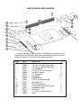
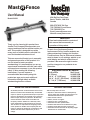
Mast R Fence
User Manual
Model #04001
124 Big Bay Point Road
Barrie, Ontario, L4N 9B4
Canada
866-272-7492 Toll Free
705-726-6145 Local Phone
705-726-6055 Fax
Email: [email protected]
Website: www.jessem.com
Thank you for choosing this product from
JessEm Tool Company. We appreciate your
support and hope that our product serves you
well. This product is designed to provide
many years of reliable service provided it is
used as intended and taken care of.
This user manual will assist you in assembly
and general operation of this product. It is
not our intent to teach you about
woodworking. It is assumed that you are an
experienced woodworker with the basic skills
and experience necessary to use this product
safely. If after reading the following
instructions, if you are unsure or
uncomfortable about safely using this
product we urge you to seek additional
information through widely available
woodworking books or classes.
JESSEM TOOL LIMITED WARRANTY
All JessEm products are warranted to be free from
defects in material and workmanship. JessEm will
repair or replace any product which upon inspection
proves to be defective for a period of (1) year from
dated receipt and proof of purchase. All warranty
claims should be made direct to JessEm Tool
Company. Contact JessEm for a warranty claim
return authorization and instructions to proceed.
The consumer is responsible for shipping costs to
return product to JessEm Tool Company. We will
repair or replace the product at our discretion and
JessEm Tool will return shipment to you at no
charge.
IMPORTANT!
Read and understand the contents of
this manual before assembly or
operation of this product.
As part of our Continuous Product
Improvement Policy, JessEm products are
always advancing in design and function.
Therefore there may be differences between
what is shown in our catalogs, website or at
retail display and what is sold at time of
purchase. We reserve the right to make
positive changes to our products at our
discretion.
Suggested Router Bit Speeds
Bit Diameter
1” (25mm)
1-1/4” - 2” (30-50mm)
2-1/4” - 2-1/2” (55-65mm)
3” - 3-1/2” (75-90mm)
Max. Speed
24,000 RPM
18,000 RPM
16,000 RPM
12,000 RPM
WARRANTY LIMITATIONS
This warranty does not cover:
! Repairs or alterations made or attempted by
anyone other than JessEm Tool Company or an
authorized JessEm service professional.
! Normal wear and tear
! Abuse, misuse or neglect.
! Improper care or maintenance.
! Continued use after partial failure.
! Products that have been modified in any way.
! Products used with improper accessories.
! Premature thread wear due to adjusting height
with electric or cordless drill.
MAST-R-FENCE PARTS DIAGRAM
16
9
15
8
14
7
11
6
10
5
4
3
2
13
1
12
**
** If you are mounting the Mast-R-Fence to a JessEm phenolic table top use the
F0048 screws item (12A) listed below. We provide both these and wood screws
which are supplied to be used for a custom table application.
ITEM #
1
2
3
4
5
6
7
8
9
10
11
12
12(A)
13
14
15
16
PART #
E0033
M0028
F0020
F0037
S0014
M0054
F0028
E0036
M0026
F0060
F0062
F0016
F0048
E0034
E0035
F0005
M0040
DESCRIPTION
1/8” x 5/8” x 11-3/4” Aluminum Scale
1/4”-20 x 1/2” Stud w/Knurled Knob
1/4”-20 x 3/4” Hex Head Cap Screw
1/4” Flat Washer
1/4” x 3/4” x 1-1/2” Fence T-Nut
Sub-Fence - Phenolic
1/4” Square Nuts
Fence Frame
Extension Knobs
1/4” x 5/8” Phillips Head Bolt
Nylon Spacer 1/2”
#6 x 3/4” Wood Screw
10-24 x 5/8” Socket Head Cap Screw
Track Mounting Angle
Fence Track
1/4”-20 x 1” Flat Head Cap Screw
Guard
QTY.
2
4
6
6
2
2
14
1
2
1
1
8
8
2
2
6
1
IMPORTANT SAFETY PRECAUTIONS
! Before operating any machinery or
power tool, read and understand all
safety instructions in the owner’s
manual for the tool or machine.
! If you do not have a manual, contact
the manufacturer and obtain one
before using any tool or machine.
! Always wear eye protection in
compliance with ANSI safety
standards when operating any power
tools or machinery.
! Always use proper guards and safety
devices when operating power tools
and machinery.
! Carefully check router bits before
each use. Do not use if damage or
defect is suspected.
! Do not exceed the recommended
RPM for any router bit.
! Do not wear loose clothing or jewelry
that may catch on tools, machinery or
equipment.
! Unplug the tool or machine when
mounting or making any adjustments
to mechanical performance.
TOOLS REQUIRED FOR ASSEMBLY:
Phillips screw driver or #3 square drive
7/16” wrench or socket
If you are not mounting to a JessEm table top
you will also need:
3/16” Drill Bit
1/16” Drill Bit
Pencil
FIG. 1
ASSEMBLING THE FENCE TRACKS
1. Using a phillips or square drive screw
driver remove the four 1/4”-20 bolts that are
used to attach the fence tracks to the back
side of the fence for packaging/shipping.
Once these bolts are removed put them
aside as you will no longer need them for
future assembly.
ROUTING SAFETY PRECAUTIONS
! Always make sure the fence on your
router table is locked firmly into
position before each use.
! Never force the bit or overload the
router beyond the expectations of the
tool.
! Be sure that at least 3/4 of the shank
length is inserted securely in the
router collet.
! Never bottom out the bit in the collet.
Allow 1/8” clearance between
bottom of shank and bottom of collet.
! Always rout in two or more passes
when large amounts of stock must be
removed.
! Use reduced RPM speeds for larger
diameter router bits.
FIG. 2
2. Take one of the fence tracks (Part #14 shown in the parts list diagram page 2) and
one of the track mounting angle (Part #13)
and align the three 1/4” threaded holes in
the angle to the slots on the fence track.
Take one of the 1/4”-20 x 3/4” hex head
bolts and place one 1/4” flat washer (Part
#4) over the bolt and thread the bolt with
washer through the slotted hole and into the
threaded hole in the fence bracket and hand
tighten to allow some movement for final
adjustment after it is mounted to the table.
Repeat step 2 for assembling the second
fence track and track mounting angle.
FIG. 3
FIG. 5
MOUNTING THE TRACKS TO THE TABLE
IF YOU ARE MOUNTING THE FENCE TO A
JESSEM TABLE TOP PROCEED TO STEP 7A.
3. Measure the distance from the front edge
of your table to the center of the bit hole in
the table top. Transfer a mark the same
distanced on both the left and right edges of
the table top. Then draw a center line across
the top of the table from one side to the
other (Fig. #3).
5. Take one of the fence track assemblies
and line it up with the mark you made in
step 4. Make a mark on the underside of
the table top to locate the same position on
the bottom of the table (Fig. 5).
FIG. 6
FIG. 4
4. From the center line you drew, come
three inches toward the front of the table and
mark a small line on both the left and right
sides of the table (Fig. #4).
6. Flip the table top over and position the
fence bracket upside down and line up the
front edge with the mark you made in step 5.
Using a pencil or a 3/16” diameter drill bit
mark the 4 holes for mounting the fence
bracket. Pre-drill the holes using a 1/16”
diameter drill bit and be sure you don’t drill
through the table top surface (Fig. 6).
7. Using the #6 x 3/4” Wood Screws (Part
#12) secure the fence track assembly to the
table.
Repeat steps 5 thru 7 for the second fence
bracket.
FOR JESSEM TABLE TOP
7A. If you are mounting the fence to a
JessEm table top the top is already predrilled for the fence mounting angle
brackets. WIth the table upside down
position the left and right fence track
assemblies and attach to the table with the
10-24 x 5/8” socket head cap screws (Part
#12A) and proceed to step 8.
FIG. 8
MOUNTING THE FENCE TO THE TRACKS
9. Slide the 3/4” x 1-1/2” rectangular T-nut
for the extension knob (Part #5) into the Tslot next to the scales on the fence track
(Fig. 8). The extension knobs (Part #9) will
thread into these nuts to hold the fence in
position. To do so, position the end of the
fence over the track and look directly down
through the open slot in the base of the
fence frame and visually line up the hole in
the rectangular T-nut. Then insert the
threaded tip of the extension knob through
the slot fence and into the threaded hole in
the T- nut (Fig. 9). Twisting the lock-down
knob clockwise will fasten the fence to the
tracks and hold the fence firmly in position.
FIG. 7
LEVELING THE FENCE TRACK
8. Place the fence on the table top in it’s
upright position and allow it to hang over the
table edge and lie across the front end of the
fence track. Raise the fence track assembly
so that it is positioned flush to the bottom of
the fence as it rests on the table top. With a
7/16” wrench or socket tighten the front bolt
of the fence assembly (Fig. 7). Move the
fence back and use it to position the rear end
of the bracket in the same way and tighten
the rear bolt. Then tighten the center bolt to
complete the leveling of the fence track.
Repeat step 8 to level the fence track on the
other side of the table.
FIG. 9
13. Slide the fence with the nylon spacer
attached into the T-slot on the left fence
track (Fig. 12). The nylon spacer should be
slightly loose to allow for some movement.
FIG. 10
ADJUSTING THE SCALES ON THE TRACKS
10. The scales on the fence tracks are
adjustable for added versatility in positioning
the fence. To adjust the scales loosen the
knurled nut underneath the fence track
adjust the scale and re-tighten the nut (Fig.
10). You can use the scales as a zero
reference point by adjusting the scales to “0”
once your fence is set up in your desired
position relevant to the router bit you are
using.
FIG. 12
14.Now slide the fence back and center the
fence left to right with the center of the bit
opening. Make sure it is parallel with the
front edge of the table or miter track.
15. Now slide the fence, keeping it square
(use the scales on the fence track to ensure
you are square) to the front of the table, just
until the nylon spacer comes out of the
track. Then tighten the bolt on the spacer
being very careful not to change it’s position
(Fig. 13).
16. Slide the fence back to the center of the
table. Re-check to see if the fence is
centered on the table. If not repeat until you
achieve your desired result.
FIG. 11
CENTERING THE FENCE TO THE TABLE
11. The Mast-R-Fence offers a unique means
of keeping the fence centered on the table
with a nylon bushing. Take the 1/4”-20 x
5/8” bolt (Part #10) and insert into the
½”nylon spacer (Part #11) and thread on one
of the square 1/4-20 nuts (Part #7). Do not
thread the square nut on all the way
12. Slide the square nut into the front T-slot
under the left end of the fence (Fig. 11).
Leave the assembly loose and approximately
1” in from the end of the fence.
FIG. 13
FIG. 14
INSTALLING THE JOINTING SHIM BEHIND
THE OUTFEED SUBFENCE.
17. Take the hex shape ball driver and
loosen the machine screws on the left side
subfence. Then slide the left subfence
completely off the left end of the fence.
FIG. 17
20. With the shim mounted to the back side
of the subfence and the square nuts
threaded onto the three machine screws,
line up each square nut and feed them one
at a time into the T-slot on the inside back
of the fence frame (Fig. 17). When all three
nuts are in the T-slot slide the subfence into
position and tighten the three machine
screws with the ball driver to complete the
installation of the shim.
FIG. 15
18. Once removed from the fence frame
take off all three of the 1/4” square
retaining nuts and set aside. Take either the
1/32” or 1/16” thick shim and line up the
three holes in the shim with the three
machine screws protruding out the
backside of the subfence.
FIG. 18
ATTACHING THE ROUTER BIT GUARD
21. Take the clear polycarbonate guard
(Part #16) and two of the black knurled
knobs (Part #2) and two 1/4” square nuts
(Part #7). Insert each knob through each
slot in the guard and thread a square nut
onto each bolt end.
FIG. 16
19. Thread the three 1/4” square nuts onto
the machine screws just until the bolt tip is
flush to the outside of the nut.
22. Line up the nut on the guard assembly
and slide each nut into the T-slot starting
from the end of the fence (Fig. 18). Then
slide the guard to the center of the fence
and adjust the guard slightly higher than
and above the router bit. Be sure the guard
clears the bit. Adjust and tighten securely
before each use and after all bit changes.
Mast R Lift Excel
Mite R Slide
MODEL 06001
The First Integrated
Lift And Phenolic Top
Combination!
MODEL 02201
The First Rail Driven
Miter Gauge & Offering
Unsurpassed Accuracy
Mast R Fence
Mast R Lift
MODEL 04001
The Heavy Weight Champion
Of Aluminim Frame
Router Table Fences!
Rout R Lift FX
MODEL 02101
From The Inventor
Of The Router LiftThe Best Made Insert
Lift On The Market!
Find Out More About Our
High Performance Tools At
MODEL 02302
www.jessem.com
A Great 2HP Lift
at a 2HP price!
Tools That Make A Difference!