1
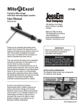
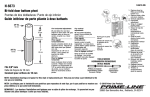
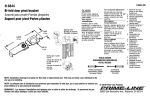
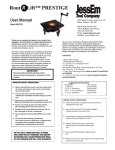
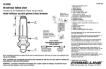
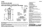
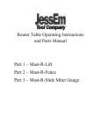
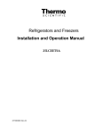
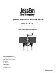
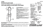
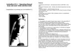
Mast R Lift
User Manual
Model #02101, 02102
124 Big Bay Point Road
Barrie, Ontario, L4N 9B4
Canada
866-272-7492 Toll Free
705-726-6145 Local Phone
705-726-6055 Fax
Email: [email protected]
Website: www.jessem.com
Thank you for choosing this product from
JessEm Tool Company. We appreciate your
support and hope that our product serves you
well. This product is designed to provide
many years of reliable service provided it is
used as intended and taken care of.
This user manual will assist you in assembly
and general operation of this product. It is
not our intent to teach you about
woodworking. It is assumed that you are an
experienced woodworker with the basic skills
and experience necessary to use this product
safely. If after reading the following
instructions, if you are unsure or
uncomfortable about safely using this
product we urge you to seek additional
information through widely available
woodworking books or classes.
Suggested Router Bit Speeds
Bit Diameter
1” (25mm)
1-1/4” - 2” (30-50mm)
2-1/4” - 2-1/2” (55-65mm)
3” - 3-1/2” (75-90mm)
Max. Speed
24,000 RPM
18,000 RPM
16,000 RPM
12,000 RPM
IMPORTANT!
Read and understand the contents of
this manual before assembly or
operation of this product.
As part of our Continuous Product
Improvement Policy, JessEm products are
always advancing in design and function.
Therefore there may be differences between
what is shown in our catalogs, website or at
retail display and what is sold at time of
purchase. We reserve the right to make
positive changes to our products at our
discretion.
CONTENTS:
1-Mast-R-Lift
1-Height Adjustment Handle
Also includes 1-Insert Ring, 1-Insert Ring
Wrench, 1-1/8” Hex Wrench, 1-Start Pin
TOOLS REQUIRED FOR ASSEMBLY:
5/16” Hex Wrench
TOOLS REQUIRED FOR ADJUSTMENT:
7/16” Wrench
IMPORTANT SAFETY PRECAUTIONS
INSTALLING THE ROUTER
! Before operating any router read and
understand all safety instructions in the
owner’s manual that came with the router.
! If you do not have a manual, contact the
manufacturer and obtain one before using
any power tool.
! Always wear eye protection in compliance
with ANSI safety standards when operating
any power tool.
! Always use proper guards and safety
devices when operating power tools and
machinery.
! Carefully check router bits before each use.
Do not use if damage or defect is
suspected.
! Do not exceed the recommended RPM for
any router bit.
! Do not wear loose clothing or jewelry that
may catch on tools or equipment.
! Unplug the tool or machine when mounting
or making any adjustments to mechanical
performance.
1. Place the crank handle into the hex hole in
the lift’s dial on the top plate. Crank the lift
carriage up so that it just contacts the O-rings at
the top of the carriage shafts. The carriage
should be all the way toward the top plate.
FIG. 1
2. With a 5/16” hex wrench, loosen the cap
screw on the carriage clamp to allow the motor to
slide into the carriage assembly (Fig. 1).
The Mast-R-Lift will accept the Porter Cable 7518
out of the box. If you are using a smaller
diameter router motor insert the adapter collar
into the opening.
DO NOT USE A CORDLESS DRILL TO
RAISE AND LOWER THE LIFT CARRIAGE.
THE AMOUNT OF FRICTION WILL CAUSE
PREMATURE WEAR OF THE THREADS
AND WILL VOID WARRANTY
ROUTER SAFETY PRECAUTIONS
! Never force the bit or overload the router
beyond the expectations of the tool.
! Be sure that at least 3/4 of the shank
length is inserted securely in the router
collet.
! Never bottom out the bit in the collet. Allow
1/8” clearance between shank and bottom
of collet.
! Always make sure the fence on your router
table is locked into position before each
use.
! Always rout in two or more passes when
large amounts of stock must be removed.
! Use reduced RPM speeds for large
diameter bits.
FIG. 2
3. Before installing the router motor, prop the
unit up on blocks of wood (Fig. 2) so the router’s
collet can extend through the centerhole in the
top plate. The motor housing must slide all the
way through and contact the inside back of the
centerhole on the plate.
Now slide the router motor into the carriage so
the top of the motor housing just makes contact
with the inside surface of the centerhole in the
top plate.
INSTALLING THE ROUTER (cont’d)
Rotate the router so that when the final
installation is made all router controls will be
positioned for convenient access. Then back the
motor off approx. 1/16” from contacting the top
plate and tighten the cap screw on the carriage
assembly.
INSTALLING A JESSEM LIFT IN A CUSTOM
ROUTER TABLE APPLICATION
A JessEm router lift is similar to using a router
mounting plate. Your table top must have a port
machined into the top. JessEm offers solid
phenolic router tables tops with pre-machined
ports for all JessEm router lifts. If you are
installing this Lift in a custom table application
you will have to fabricate this opening yourself.
JessEm offers a separate template for this
operation. See your JessEm distributor for the
proper template for your JessEm router lift.
FIG. 4
ADJUSTING THE FIT IN THE TABLE PORT
Your Mast-R-Lift comes with adjustable snugger
bars to allow for a tight fit in the table top
opening and eliminate any movement of the
plate. Use the 1/8” hex wrench provided to
loosen the cap screws on the snugger bars. Move
the bars out slightly and check for fit. Adjust
again if necesssary.
TAB-LOC PHENOLIC INSERT RINGS
Your Mast-R-Lift comes with one insert ring with a
pre-drilled center hole. Additional ring sets are
available with different diameter pre-drilled holes
and/or no pre-drilled holes for creating your own
custom centerhole diameters. See your JessEm
distributor for these and other accessories
FIG. 3
LEVELING THE LIFT IN THE TABLE TOP
1. The Mast-R-Lift features built-in plate levelers
to adjust the surface of the top plate flush with
the router table surface (Fig. 3). Using the 1/8”
hex wrench included with your lift adjust all four
levelers so they are flush with the underside of
the plate surface. Then place the lift in the table
top and determine amount of adjustment
needed. Take the lift out of the table and make
the same amount of adjustment on all four
levelers. Be sure to make all adjustments equal
in terms of rotations and/or fractions of a
rotation. Place the lift back in the table top and
check for level. If necessary repeat until desired
level is achieved.
Note: If you are using a JessEm table top there
are pre-drilled holes in the bottom of the table to
allow access from underneath the table. This
allows you to make the leveling adjustment with
the Lift installed in the table top.
FIG. 5
1. Place the insert ring into the centerhole of
the Lift’s top plate (Fig. 5).
2. With the insert wrench provided, insert the
prongs of the wrench into the corresponding
holes in the insert ring and turn the insert ring
counter clockwise to tighten.
3. Turn the insert wrench clockwise to loosen
and remove the ring. If the insert ring becomes
too tight to loosen with hand pressure, a tap
clockwise on the insert wrench with a block of
wood will loosen it.
USING YOUR MAST-R-LIFT
To raise your router, turn the height adjustment
handle clockwise. To lower, turn the handle
counter-clockwise. Keep in mind that one
complete revolution equals 1/16” of change.
When your adjustment is complete, remove the
handle and place somewhere off the work
surface for safety. Refer to the chart below for
fractional and decimal adjustments based on
amount of revolutions made.
Fraction
Decimal
1/64”
1/32”
1/16”
1/8”
1/4”
1/2”
0.016”
0.031”
0.062”
0.125”
0.250”
0.500”
Number of
Revolutions
1/4 Revolution
1/2 Revolution
1 Revolution
2 Revolutions
4 Revolutions
8 Revolutions
RE-ADJUSTING THE THREAD TENSIONING
2. With a 7/16” open end wrench, (Fig. 6)
loosen the 1/4” - 20 hex nut that is located on
the right side of the brass post next to the
threaded rod. Then use a hex wrench to back out
the set screw that threads through the nut until
the brass tensioning collar can be turned.
3. Rotate the brass tensioning collar with
vertical grooves, so it tightens against the rubber
washer. Note: a drop of oil on the rubber washer
eases the rotation of the brass collar.
4. Be certain when you tighten the brass collar
the set screw seats in one of the vertical grooves.
5. Tighten the 1/4”-20 nut with the 7/16”
wrench again and the adjustment is complete.
JESSEM TOOL LIMITED WARRANTY
All JessEm Lifts feature our patented thread
tensioning design. This feature is why it is not
necessary to lock the router into position after
setting the cutting height. The design keeps
tension on the position wherever you set the
height. Thread tension is set at the factory and
depending on the amount of use you may have to
reset this adjustment periodically. If the bit height
ever begins to change (or drop) during use, the
thread tensioning likely needs to be reset.
All JessEm products are warranted to be free
from defects in material and workmanship.
JessEm will repair or replace any product which
upon inspection proves to be defective for a
period of (1) year from dated receipt and proof
of purchase. All warranty claims should be
made direct to JessEm Tool Company. Contact
JessEm for a warranty claim return authorization
and instructions to proceed. The consumer is
responsible for shipping costs to return product
to JessEm Tool Company. We will repair or
replace the product at our discretion and
JessEm Tool will return shipment to you at no
charge.
WARRANTY LIMITATIONS
FIG. 6
1. Turn the Lift upside down on a table with the
threaded height adjustment rod facing you.
This warranty does not cover:
! Repairs or alterations made or attempted by
anyone other than JessEm Tool Company or
an authorized JessEm service professional.
! Normal wear and tear
! Abuse, misuse or neglect.
! Improper care or maintenance.
! Continued use after partial failure.
! Products that have been modified in any way.
! Products used with improper accessories.
! Premature thread wear due to adjusting
height with electric or cordless drill.