1
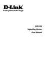
Building Networks For People DIR-100 Triple Play Router User Manual CONTENTS Before You Start..........................................................................................................................................iii Packing List.................................................................................................................................................iii Installation Notes.........................................................................................................................................iv Installation Information.................................................................................................................................v INTRODUCTION............................................................................................................................1 Router Description and Operation.................................................................................................................1 Router Features.............................................................................................................................................1 Front Panel....................................................................................................................................................2 Rear Panel ....................................................................................................................................................3 CONNECTING THE ROUTER.......................................................................................................4 Connect Router to Ethernet LAN............................................................................................................4 Connect VLAN Ports to Audio/Video Network Hardware...........................................................................4 Power On Router..........................................................................................................................................5 Reset.............................................................................................................................................................5 ROUTER CONFIGURATION.........................................................................................................6 IP Settings on Your Computer.............................................................................................................................6 Accessing the Configuration Manager.................................................................................................................7 Log in............................................................................................................................................................8 Web Manager................................................................................................................................................9 Internet Setup........................................................................................................................................10 Setup Wizard..........................................................................................................................................11 WAN Settings ........................................................................................................................................15 Dynamic IP Address...................................................................................................................................16 Static IP Address.........................................................................................................................................17 PPPoE.........................................................................................................................................................18 VLAN Settings...........................................................................................................................................19 DNS Settings..............................................................................................................................................20 LAN Settings..........................................................................................................................................21 DHCP Clients List......................................................................................................................................22 Advanced Settings................................................................................................................................23 NAT Settings..............................................................................................................................................23 Virtual Server....................................................................................................................................................24 Special Application............................................................................................................................................25 Port Mapping.....................................................................................................................................................26 ALG...................................................................................................................................................................27 DMZ..................................................................................................................................................................28 DDNS Settings..................................................................................................................................................29 Firewall.......................................................................................................................................................30 Client Filtering...................................................................................................................................................32 MAC Control.....................................................................................................................................................33 Routing.......................................................................................................................................................34 Static Routing....................................................................................................................................................34 Dynamic Routing...............................................................................................................................................35 UPnP...........................................................................................................................................................36 Port Mapping (UPnP)........................................................................................................................................36 System...................................................................................................................................................37 System Status....................................................................................................................................................38 System Settings.................................................................................................................................................39 Administrator Settings.......................................................................................................................................40 Firmware Upgrade ............................................................................................................................................41 Configuration Tools...........................................................................................................................................41 System Log........................................................................................................................................................42 TECHNICAL SPECIFICATIONS..................................................................................................43 CONFIGURING IP SETTINGS ON YOUR COMPUTER.............................................................45 DIR-100 Triple Play Router Before You Start Please read and make sure you understand all the prerequisites for proper installation of your new Router. Have all the necessary information and equipment on hand before beginning the installation. Overview The procedure to install the Router can be described in general terms in the following steps: 1. Gather information and equipment needed to install the device. Before you begin the actual installation make sure you have all the necessary information and equipment. 2. Install the hardware, that is, connect the cables to the device and connect the power adapter. 3. Check the IP settings on your computer and change them if necessary so the computer can access the web-based software built into the Router. 4. Use the web-based management software to configure the device to suit the requirements of your ISP account. Packing List Open the shipping carton and carefully remove all items. In addition to this Manual, ascertain that you have: DIR-100 Ethernet Broadband Router Power Adapter Ethernet Cable Quick Installation Guide Manual on CD If any of the above items are missing, please contact your reseller. CAUTION: The Router must be used with the power adapter included with the device. iii DIR-100 Triple Play Router Installation Notes In order to establish a connection to the Internet it will be necessary to provide information to the Router that will be stored in its memory. For some users, only their account information (User Name and Password) is required. For others, various parameters that control and define the Internet connection will be required. Internet Connection The DIR-100 is intended for use with a broadband device such as an ADSL, DSL or cable (CATV) modem. The physical connection to the Internet must first be established through a broadband device, typically this should be set up as an invisible bridge. Operating Systems The DIR-100 uses an HTML-based web interface for setup and management. The web configuration manager may be accessed using any operating system capable of running web browser software, including Windows 98 SE, Windows ME, Windows 2000, and Windows XP. Web Browser Any common web browser can be used to configure the Router using the web configuration management software. The program is designed to work best with more recently released browsers such as Opera, Microsoft Internet Explorer® version 5.0, Netscape Navigator® version 4.7, or later versions. The web browser must have JavaScript enabled. JavaScript is enabled by default on many browsers. Make sure JavaScript has not been disabled by other software (such as virus protection or web user security packages) that may be running on your computer. Ethernet Port (NIC Adapter) Any computer that uses the Router must be able to connect to it through the Ethernet port on the Router. This connection is an Ethernet connection and therefore requires that your computer be equipped with an Ethernet port as well. Most notebook computers are now sold with an Ethernet port already installed. Likewise, most fully assembled desktop computers come with an Ethernet NIC adapter as standard equipment. If your computer does not have an Ethernet port, you must install an Ethernet NIC adapter before you can use the Router. If you must install an adapter, follow the installation instructions that come with the Ethernet NIC adapter. iv DIR-100 Triple Play Router Installation Information Print this page and record the listed information here in case you have to re-configure your WAN connection in the future or reset the device configuration settings. Information you will need from your Internet service provider: Username (PPPoE connections) This is the Username that is used to log on to your Internet service provider’s network. It is commonly in the form [email protected]. Password (PPPoE connections) This is the Password that is used, in conjunction with the Username above, to log on to your Internet provider’s network. Internet Connection Type This is the method that your ISP uses to send and receive data between the Internet and your computer. Record your info here. Information you will need about your DIR-100 Ethernet Broadband Router: Username This is the Username you will be prompted to enter when you access the DIR-100 configuration screens using a Web browser. The default Username is admin. Password This is the Password you will be prompted to enter when you access the DIR-100’s configuration windows using a Web browser. There is no initial Password. LAN IP address of the DIR-100 This is the IP address you will enter into the Address field of your Web browser to access the DIR-100’s configuration windows using a Web Browser. The default IP address is 192.168.0.1. LAN Subnet Mask of the DIR-100 This is the subnet mask used by the DIR-100, and will be used throughout your LAN. The default subnet mask is 255.255.255.0. Record your info here. Information you will need about your LAN or computer: DHCP Client status Your DIR-100 Router is configured, by default, to be a DHCP server. This means that it can assign an IP address, subnet mask, and a default gateway address to computers on your LAN. The range of IP addresses the DIR-100 will assign are from 192.168.0.100 to 192.168.0.199. Your computer (or computers) needs to be configured to Obtain an IP address automatically (that is, they need to be configured as DHCP clients.) v Record your info here. DIR-100 Triple Play Router 1 Introduction This section provides a brief description of the Router, its associated technologies and a list of Router features. Router Description and Operation The D-Link DIR-100 Triple Play Router is designed to provide connectivity for your private Ethernet LAN to share an Internet connection via a broadband technology. The broadband connection may be in any common form including DSL or cable modems. The DIR-100 is specially configured for use with premium IP services such as VoIP and Movies on Demand. Two ports are configured specially for streaming for VoIP, digital media servers and TV set top controllers. The Triple Play Router is ideally suited for broadband Internet, Video and Voice services over IP. The DIR-100 is compatible with most popular operating systems, including Macintosh, Linux and Windows, and can be integrated into an existing network. Router Features The D-Link DIR-100 Triple Play provides the following features: Two VLAN ports optimized for digital audio/video service. Two NAT Ports connect multiple computers to share the Internet connection Broadband Modem and IP Sharing - Connects multiple computers to a Broadband (Cable or DSL) modem to share the Internet connection. Ethernet Switch - Allows you to quickly and easily share an Internet connection with multiple computers and devices. Advanced Firewall, MAC Filtering, and WebSite Filtering Features - The Web-based user interface displays a number of advanced network management features including: Web-Based Management - DIR-100 is configurable through any network computer’s web browser using Netscape or Internet Explorer. Port Forwarding Supported - Enables you to expose WWW, FTP and other services on your LAN to be accessible to Internet users. Special Application Supported - Special applications requiring multiple connections, like Internet gaming, video conferencing, Internet telephony and so on. The DIR-100 can sense the application type and open a multi-port tunnel for it. DMZ Host Supported - Allows a networked computer to be fully exposed to the Internet. This function is used when the Special Application feature is insufficient to allow an application to function correctly. 1 DIR-100 Triple Play Router Front Panel Place the Router in a location that permits an easy view of the LED indicators on the front panel. Status LED WAN LED Power LED LAN LEDs The LED indicators on the front panel include the Power, Status, WAN, and LAN for the Ethernet ports. Power Steady green light indicates the unit is powered on. Status This lights steady green when the device is first powered on, then blinks green when the system status is normal, that is, when the device is functioning properly. A prolonged steady green light indicates a problem. WAN Port Lights steady green when the WAN (Internet) connection is established and blinks green when there is activity on the WAN port. LAN Ports Lights steady green when the LAN (Ethernet) connection is established and blinks green when there is activity on the corresponding LAN port. 2 DIR-100 Triple Play Router Rear Panel Connect the power adapter cord and network cables on the rear panel. The reset button is also located on the back of the device. Note: The computer used to manage the computer must be connected to one of the NAT ports (3 or 4) or it will not be able to connect to the Router’s management software. Note: For multiple function on DIR-100, the “NAT” & “VLAN” words will not be seen on the real device. Power Adapter LAN Ports Connect NAT ports (3&4) to Ethernet devices, VLAN ports (1&2) to audio/visual network hardware. WAN Port Reset Button NAT (#1 and #1) VLAN (#3 and #4) Connect two NAT ports (3&4) to Ethernet devices such as switches, computers and wireless access points. The computer used to manage the Router must be connected to ports 3or 4 (NAT port). VLAN ports (1&2) are specially configured for premium IP services such as video on demand and VoIP. WAN Connect to broadband device such as an ADSL or cable modem. Power Adapter Insert power adapter into receptacle and plug into a suitable power source. Reset Button Use this to reset the device to default settings including IP settings and administrator access information. LAN Ports Note: All ports (LAN and WAN) are Auto-MDIX. All ports also automatically connect with straight-through or crossover CAT5 or better Ethernet cable. 3 DIR-100 Triple Play Router 2 Connecting the Router The Router provides the connection between two networks, a private Ethernet LAN and the public Internet (WAN). Choose a location for the Router where Ethernet devices can be connected to the LAN ports and the WAN port can be connected to the cable modem or DSL modem that provides the broadband Internet connection. The Router, devices should be protected from dust, water, moisture and heat. Make sure network cables, power adapters and power cords are placed safely out of the way so they do not create a tripping hazard. As with any electrical appliance, observe common sense safety procedures. Place the Router on a shelf, desktop, or other stable platform. Ideally you should be able to view the LED indicators on the front panel. Connect Router to Ethernet LAN The Router can be connected to computers or other Ethernet devices using the four Ethernet LAN ports on the rear panel. Any connection to an Ethernet concentrating device such as a switch or hub must operate at a speed of 10/100 Mbps only. When connecting the Router to any Ethernet device capable of operating at speeds between 10~100Mbps, be sure that the device has auto-negotiation (NWay) enabled for the connecting port. Use standard CAT5 or better Ethernet cable with RJ-45 connectors. The Ethernet LAN ports are auto MDI-II/MDI-X so you can use straight-through or crossover Ethernet cabling. The rules governing Ethernet cable lengths apply to all LAN to Router connections. Be sure the Ethernet cables connected to the LAN ports do not exceed 100 meters in length. The ports labeled NAT are intended for use by standard Ethernet devices such as switches, wireless access points and computers. There are no special considerations when connecting Ethernet devices to these ports. Make sure the computer used to manage the Router is connected through one of the NAT ports (3 or 4). Connect VLAN Ports to Audio/Video Network Hardware The two VLAN ports (1 & 2) are specially configured for direct connection to digital media servers and VoIP equipment or any media device with broadcast/multicast capabilities. All Ethernet LAN ports, including the VLAN ports are configurable for VLAN ID and priority setting. If the VLAN ports are connected to intermediate devices such as a switch, make sure the port is properly configured for VLAN settings, ID and priority settings, and so forth, in order to maintain the optimized configuration along the entire path. For example, if the VLAN ports are connected to a switch port that is on a different VLAN, transmission of any type of data will not be possible. 4 DIR-100 Triple Play Router Power On Router To power on the Router: CAUTION: The Router must be used with the 1. Insert the AC Power Adapter power adapter included with the device. cord into the power receptacle located on the rear panel of the Router and plug the adapter into a suitable nearby power source. See the back panel illustration above to view the power receptacle. 2. The Power LED indicator will immediately light green and remain lit. The Status LED should light steady green initially and begin to blink after a few seconds. 3. If you have the Router connected to your network you can look at the Ethernet Link/Act LED indicators to make sure they have valid connections. The Router will attempt to establish the WAN connection, if the WAN line is connected and the connection is properly configured this should light up after several seconds. Reset To reset the system settings to factory defaults, please follow these steps: 1. Leave the device powered on, do not disconnect the power. 2. Press the reset button and hold (use a paper-clip). See the back panel illustration above to view the location of the reset button. 3. Keep the button pressed about 4 seconds. 4. Release the button. The DIR-100 will then automatically reboot itself. Upon restarting the Router will load the factory default configuration settings including the default IP address 192.168.0.1 a subnet mask 255.255.255.0 and the DHCP server active. 5 DIR-100 Triple Play Router 3 Router Configuration The first time you setup the Router it is recommended that you configure the WAN connection using a single computer making sure that both the computer and the Router are not connected to the LAN. Connect the computer directly to either NAT port, port 3 or 4 Once the WAN connection is functioning properly, you may continue to make changes to Router configuration including IP settings and DHCP setup. This chapter is concerned mainly with using your computer to configure the WAN connection. Instructions are also provided for basic LAN configuration. The following chapter describes how to set up the advanced features of the Router. Note: The computer used to manage the computer must be connected to one of the NAT ports or it will not be able to connect to the Router’s management software. IP Settings on Your Computer In order to configure your system to receive IP settings from the Router it must first have the TCP/IP protocol installed. If you have an Ethernet port on your computer, it probably already has TCP/IP protocol installed. See Appendix B for instruction on how to configure Windows computers to be DHCP clients. For computers running non-Windows operating systems, follow the instructions for your OS that configure the system to receive an IP address from the Router, that is, configure the system to be a DHCP client. For computers using manually configured IP settings, make sure the IP address is on the same subnet as the Router. The computer should use an IP address in the range 192.168.0.2 to 192.168.0.254 with a subnet mask of 255.255.255.0. 6 DIR-100 Triple Play Router Accessing the Configuration Manager Now that your computer’s IP settings allow it to communicate with the Router, you can access the configuration software. To use the web-based management software, launch a suitable web browser and direct it to the IP address of the Router. Type in http:// followed by the default IP address, 192.168.0.1 in the address bar of the browser. The URL in the address bar should read: http://192.168.0.1. Once entered, the user will be prompted to enter the username and password to access the Configuration Manager, as show below. A new window will appear and you will be prompted for a user name and password to access the web-based manager. NOTE: The wrong proxy server settings on your browser can prevent connection to the web manager. If you are having trouble connecting to the web interface of the Router, configure the proxy settings to bypass the proxy server or disable use of proxy servers and try to connect again. To check proxy setting for Windows Internet Explorer: 1. In Windows, click on the Start button, go to Settings and choose Control Panel. 2. In the Control Panel window, double-click on the Internet Options icon. (Alternatively you can access this Internet Options menu using the Tools pull-down menu in Internet Explorer.) 3. Click the Connections tab and click on the LAN Settings button. 4. Verify that the “Use proxy server” option is NOT checked. If it is checked, click in the checked box to deselect the option and click OK. 7 DIR-100 Triple Play Router Log in Use the default user name “admin” and no password for first time setup. You should change the web-based manager access user name and password once you have verified that a connection can be established. The user name and password allows any PC within the same subnet as the Router to access the web-based manger. Log in 8 DIR-100 Triple Play Router Web Manager The Web Manager used for configuration uses directories to organize the various menus used to configure and monitor the Router. The first page that appears after logging in is the System Status display in the System menu directory. Click to access menu directories: System, WAN, LAN, NAT, Firewall, Routing and UPnP. Click to access menu System Status display (first page to appear when logged in) 9 DIR-100 Triple Play Router The table below lists the various configuration and display menus found in each menu directory. The page number below the menu directory title is the first page of the description of the menus found in that directory. Directory Contents Wizard Page 11 System Page 37 WAN Page 15 LAN Page 21 NAT Page 23 Firewall Page 30 Routing Page 34 UPnP Page 36 Help The setup wizard is used to quickly configure the Internet connection. Use the wizard to configure the Router for PPPoE, Dynamic IP and Static IP Internet connections. These menus are used for administration and maintenance; menus include: System Status, System Settings, Administrator Settings, Firmware Upgrade, and Configuration Tools. These menus are used for manual configuration of the Internet connection, VLAN configuration and DNS settings; menus include: Connected Type, VLAN Settings and DNS. Use these menus to configure IP settings and DHCP service for the private LAN; menus include LAN Settings and DHCP Client List. These advanced settings menus are used to configure the Router to use applications and protocols that might not be compatible with NAT; menus include Virtual Server, Special Application, Port Mapping, ALG, DMZ and DDNS Settings. Use these advanced settings menus to control what traffic is allowed or denied through the Router; menus include Firewall Options, Client Filtering and MAC Control. Use the advanced Routing menus to view the contents of the routing table, or to configure static routing static routing and configure the role of the router on the network; menus include Routing Table, Static Routing and Dynamic Routing. The UPnP Settings is used to enable and configure UPnP and view Port Mapping for UPnP. An html-based menu with hyperlinks to description of the various menus contained in the web manager. Internet Setup The Router’s Internet connection can be configured using the Setup Wizard or set up manually. To access the Internet connection Setup Wizard, click on the Wizard menu directory and follow the instructions for set up. To configure the Internet connection manually, click on the WAN settings directory and configure the Connection Type accordingly. 10 DIR-100 Triple Play Router Setup Wizard To use the Setup Wizard, open the Wizard menu directory. Wizard menu Enter a Host Name and Domain Name for the Router, or accept the default names. Choose the Time Zone and configure and enable Daylight Saving dates where appropriate. Click the Next button to go the WAN Settings configuration menu. Click on the type of connection (Dynamic IP, Static IP or PPPoE) used for your Internet service, the configuration menu for the connection type chosen appears. Follow the instructions below according to the type of Internet connection. Setup Wizard – Configure Dynamic IP Address Connection 11 DIR-100 Triple Play Router For Dynamic IP Address connections, the MAC address of your Ethernet adapter can be copied to the Router. Some ISPs use the unique MAC address of your computer’s Ethernet adapter for identification and for IP address assignment (DHCP) when you first access their network. This can prevent the Router (which has a different MAC address) from being allowed access to the ISP’s network (and the Internet). To clone the MAC address of your computer’s Ethernet adapter, select Enabled for MAC Cloning and click the Clone MAC Address button. Click Next to continue. DHCP Connection Setting Description MAC Cloning To use MAC Cloning, click to select the Enabled option and click on the Clone MAC Address button. MAC Address If you clone the MAC address of your computer to the Router, the MAC address will appear here. This will be the MAC address recorded by the ISP’s server when the connection is initiated. Clone MAC Address The default MAC address is set to the Internet’s physical interface MAC address on the Broadband Router. You can use the Clone MAC Address button to copy the MAC address your computer’s Ethernet Card to the Router. Setup Wizard – Configure Static IP Address Connection 12 DIR-100 Triple Play Router For Static IP Address connection types, you must type in the IP Address, Subnet Mask, and ISPGateway Address, the ISP provides this information. Click Next to continue. Static IP Connection Setting Description IP address assigned by your ISP The public or global IP address provided by your ISP. WAN Subnet Mask The Subnet Mask used for the Internet. This should also be provided by your ISP WAN Gateway Address The IP address of the gateway router owned by your ISP. Your ISP should provide this IP address. 13 DIR-100 Triple Play Router Setup Wizard – Configure PPPoE Connection For PPPoE connections, type in the User Name and Password used to identify and verify your account to the ISP. Retype the password again and if necessary, type a Service Name or domain name. The MTU value Click Next to continue. PPPoE Setting Description User Name The PPPoE user name used to establish the identity of your ISP account. Typically this is in the form [email protected] - some users may be allowed to select a personalized user name for their account. Password Enter the password used to verify the identity of your account. Your ISP may have provided this to you or you might have chosen a personalized password that is easy to remember. The password is case-sensitive, so type the characters exactly as given to you. Retype Password Retype the password exactly as entered in the previous field. Service Name Enter the Service Name provided by your ISP if necessary (optional). MTU This field refers to the Maximum Transfer Unit, which is the maximum size of a packet, in bytes, that will be accepted by the router. The default setting is 1492 bytes. For high bandwidth Internet connections where lag time is generally not a problem, the default MTU should be used. Maximum Idle Time This is the time allowed for the PPP connection to remain idle without logging out. This is useful when using an ISP account with a time based fee structure. 14 DIR-100 Triple Play Router WAN Settings Manual Internet Connection The Internet connection can be configured manually without using the Setup Wizard. To continue Internet connection settings manually click on the WAN menu directory link. The first menu to appear is the Connected Type menu. Select the type of Internet connection and configure it accordingly. WAN Settings – Connected Type menu Configure the Internet connection according to the type of connection used and click the OK button to save and apply the settings. 15 DIR-100 Triple Play Router Dynamic IP Address A Dynamic IP Address connection configures the Router to automatically obtain its global IP address from a DHCP server on the ISP’s network. To configure a Dynamic IP Address connection, perform the steps listed below. Dynamic IP Address connection setup menu To configure a Dynamic IP Address Internet connection, follow these steps: 1. Click to select the Dynamic IP Address option. 2. Leave the MTU value at the default setting (default = 1500) unless you have specific reasons to change it. 3. Some ISPs record the unique MAC address of your computer’s Ethernet adapter when you first access their network. This can prevent the Router (which has a different MAC address) from being allowed access to the ISPs network (and the Internet) if the Internet connection has already been established. To copy the computer’s MAC address to the Router in order to allow access, MAC cloning should be used. Click to select the Enabled box if MAC Cloning will be used. 4. To clone the computer’s MAC address to the Router, click the Clone MAC Address button. 5. Click on the OK button to save and apply the new Internet connection settings. 16 DIR-100 Triple Play Router Static IP Address When the Router is configured to use Static IP Address assignment for the Internet connection, you must manually assign a global IP Address, Subnet Mask, and ISP Default Gateway IP address. Most users will also need to configure DNS server IP settings. Follow the instruction below to configure the Router to use Static IP Address assignment for the Internet connection. Static IP Address connection setup menu To configure a Static IP type Internet connection, follow these steps: 1. Select the Static IP option. 2. Type an IP Address, Subnet Mask and ISP Gateway Address as supplied by the ISP. 3. Leave the MTU value at the default setting (default = 1500) unless you have specific reasons to change it. 4. If using multiple static IP addresses, select the Yes option to answer the question Does ISP provide more IP addresses? An additional entry field appears to add another IP address. Enter additional static IP addresses and click the Add button to add the IP address to the addresses available to the Router. 5. Click on the OK button to save and apply the new Internet connection settings. 17 DIR-100 Triple Play Router PPPoE PPP or Point-to-Point protocol is a standard method of establishing a network connection/session between networked devices. To configure the connection for PPPoE, perform the steps listed below. The information that is to be provided in this window must be given to you by your ISP and must be carefully configured. Follow the instructions below to configure the Router to use a PPPoE Internet connection. PPPoE connection setup menu To configure a PPPoE Internet connection, follow these steps: 1. Select the PPPoE option. 2. Type the User Name and Password used for your account. A typical User Name will be in the form [email protected] Type the password again in Please retype your password. 3. Leave the MTU value at the default setting (default = 1492) unless you have specific reasons to change it. 4. Choose the desired Connection Mode; options are keep-alive, used to maintain the connection at all times after is has been established, auto-connect to connect every time an Internet connection is attempted from the LAN if it is not already connected, and manual-on to establish the PPP connection manually. For manual-on connections, use the Connection button on the System Status menu to begin the PPP session and use the Disconnected button to terminate the PPP session. Autoconnect mode requires and idle timeout. Use the Maximum Idle Time field to configure the time in seconds that the Router remains idle without terminating the PPP session. 18 DIR-100 Triple Play Router VLAN Settings The ports labeled VLAN on the Router, ports 1 and 2, are pre-configured for VLAN and 802.1p priority settings intended to support value added service like VoIP/Video streaming. The VLAN ports, ports 1 and 2, can also be configured separately for priority and VLANs if desired. The NAT ports 3 and 4 are configured in tandem, they have identical PVID (Port VLAN Identifier) and 802.1p priority settings. VLAN Settings menu The port VLAN identifier or PVID is used to indicate membership of the port-based VLAN. VLAN membership in conjunction with priority setting can be used to expedite time sensitive data frames such as video or audio streaming from media servers etc. If the DIR-100 is used on a network with other VLAN supporting devices, such as 802.1Q VLAN switches, it is important to make certain that all the ports on these switches used for VoIP or streaming video are on the same VLAN, that is use the same PVID, and have identical 802.1p priority settings. The 802.1p Priority setting for the VLAN ports are used to give high priority to properly 802.1p tagged data frames passing through the port. Since the primary function of these ports is to support voice, audio and video network applications and hardware, the priority setting should be high. Priority tags are given values from 0 to 7 with 0 being assigned to the lowest priority data and 7 assigned to the highest. The Management PVID is used to identify the VLAN from which management instructions are sent. For example, management of a multicast VLAN set up on the network might have a designated management VLAN. This is where IGMP snooping and other broadcast/multicast control and information packets will originate when properly configured on switches that support such management. 19 DIR-100 Triple Play Router DNS Settings Use the DNS settings menu to set up DNS relay or static DNS service for LAN clients. DNS settings menu Use the DNS Proxy option to relay DNS settings automatically from the ISP to properly configured LAN side clients. To use manually configured DNS settings, select the Static DNS Server option. To disable all DNS function from the Router, make sure neither option is selected. If both Static DNS and DNS proxy are used, the option to Search Static DNS First can be selected to designate the manually configured DNS server as the preferred DNS server. 20 DIR-100 Triple Play Router LAN Settings Use the LAN Settings menu to configure the IP settings of the Router and enable the Router’s DHCP server. With DHCP enabled, the Router can provide IP settings automatically for 253 clients on the private LAN. LAN Settings menu Type the new IP Address and click the OK button configure a new IP address of the Router. If DHCP is enabled, the Router’s IP address will be the base address for the pool of available IP addresses. The Router’s Subnet Mask is not configurable by the user. DHCP is enabled by default. To stop DHCP service click to remove the check form the Enabled box for Gateway acts as DHCP server. The DCHP pool of available IP addresses is configured entering a range of IP addresses for DHCP. Type the last segment of the Starting Address and Ending Address to define the DHCP pool. Choose the Lease Time allowed for clients to hold an assigned IP address. Click the OK button to apply and save the new LAN IP settings. The configurable IP pool for DHCP changes automatically to accommodate a change in the Router’s IP address. 21 DIR-100 Triple Play Router DHCP Clients List The DHCP Client List displays active DHCP clients. To reserve a Static IP address for a DHCP client on the list, click the Static option box for the client, it will appear in the Static Client menu. Click the OK button to assign the IP address as a Static IP address. This will remove the IP address form the available pool of IP addresses used for DHCP. DHCP Clients list and Static IP menu To manually configure a Static IP address assignment for a DHCP client that is not currently listed, type the last segment of the IP address, the MAC Address and Host Name of the client in the entry fields provided and click on the Add button. 22 DIR-100 Triple Play Router Advanced Settings Configuration menus contained in the NAT Settings, Firewall, Routing and UPnP menu directories are used to configure the more advanced network settings. These menus are described in the next few sections. NAT Settings The NAT Settings menus are used to configure single, multiple and trigger port forwarding as well DDNS and DMZ setup. The ALG menu is used to configure pass-through for commonly used network applications that conflict with NAT. NAT Settigns – Virtual Server menu 23 DIR-100 Triple Play Router Virtual Server The Virtual Server menu is used to configure single port forwarding to specified IP addreses on the LAN. Typically this is used to forward requests to LAN side servers from the WAN. Virtual Server menu Enter the destination Private IP address on the LAN side, this is the station or server that recieves the single port forwarding as defined by the rule. Configure the Private Port (LAN side) and port Type, the Public Port (WAN side) and enter a Comment to describe the rule if desired. Rules can be Enabled or disabled at any time. Click OK to apply and save the new forwarding rule. 24 DIR-100 Triple Play Router Special Application The Special Application menu is used for trigger port forwarding from the LAN, typically for common network applications using standard ports that trigger the rule created for it when detected. Special Application menu Configure the Trigger Port or range of ports and Trigger Type for a rule. Enter the Public Port and Public Type used for the application. Rules can be Enabled or disabled at any time. Click OK to apply and save the new forwarding rule. 25 DIR-100 Triple Play Router Port Mapping Use port mapping to map public ports to specified servers on the LAN. Port Mappipng menu Configure the LAN side Server IP address, the Mapping Port or range of ports and Type for a rule (type a port range using the format xxx-xxx, for example, 4367-4375). Rules can be Enabled or disabled at any time. Click OK to apply and save the new forwarding rule. 26 DIR-100 Triple Play Router ALG The Application Level Gateway menu is used to create pass-through rules for network applications that conflict with NAT. ALG menu Enable any listed pass-through rule by clicking to select the option box for that rule. A non-standard FTP port can be specified. Click the OK button to apply and save the pass-through settings. 27 DIR-100 Triple Play Router DMZ Firewalls may conflict with certain interactive applications such as video conferencing or playing Internet video games. For these applications, a firewall bypass can be set up using a DMZ IP address. The DMZ IP address is a “visible” address and does not benefit from the full protection of the firewall function. DMZ menu One DMZ IP address can be added for each public IP address. If your ISP account uses one public IP address, then only one DMZ host is allowed. Click OK to apply and save teh DMZ host setting. 28 DIR-100 Triple Play Router DDNS Settings The DIR-100 supports DDNS or Dynamic Domain Name Service. Dynamic DNS allows a dynamic public IP address to be associated with a static host name in any of the many domains, allowing access to a specific host from various locations on the Internet. With this function enabled, remote access to a host will be allowed by clicking a URL hyperlink in the following form: hostname.dydns.org Because many ISPs assign public IP addresses using DHCP, it can be difficult to locate a specific host on the LAN using the standard DNS. For example, if you are running a public web server or VPN server on your LAN, DDNS ensures that the host can be located from the Internet if the public IP address changes. DDNS requires that an account be set up with one of the supported DDNS servers. Dynamic DNS menu To implement Dynamic DNS, first click to select the Enabled option and select the DDNS Server from the list in the pull-down menu. Next, enter the Host Name of the LAN to be accessed, and the Username and Password for the DDNS account. Click the OK button to save changes made. The DDNS Retry is used to update the DDNS server in case the host IP address is changed by the ISP. 29 DIR-100 Triple Play Router Firewall Configuration menus in the Firewall directory are used to filter or block specific traffic from teh WAN side or to deny access to the WAN from the LAN by specified stations bassed on MAC or IP address. Firewall Options Click to select and enable the Firewall option from the list and click the OK button to apply. 30 DIR-100 Triple Play Router Click the Advanced Settings button to view more Firewall options. Firewall Options menus 31 DIR-100 Triple Play Router Client Filtering Clients on the LAN side can be filtered by IP address using the Client Filtering menu. Client Filtering menu To use IP-based client filtering, click to select the Enable Client Filter box and configure the rules. For each new fultering rule define the IP adress or address range, each rule allows definition of port, port range and port type, if no port is defined the rule will block all traffic. Schedules can be created to block at sepecified times and/or days. Each rule can be enabled or disabled at any time. Click OK to apply and save the new filtering rules. 32 DIR-100 Triple Play Router MAC Control The MAC Control menu is used to specify MAC addresses that are either denied or allowed WAN access as a group. This is especially for wireless networks. MAC Control menu Select a client MAC address form the pull-down menu or type in a MAC address to be added. Click the Add button to place the MAC address on the list. Filtering options for MAC addresses are to eitehr Accept or Filter out (deny) access to the WAN side for the entier list. Click teh Enabled box to apply the filter and click the OK button to apply and save the MAC filter rules. 33 DIR-100 Triple Play Router Routing The Routing menus are used to view the routing table and setup static routing. Routing Table Click Refresh to update the routing table. Static Routing Use Static Routing to specify a route used for aggregate traffic distributed to multiple routers within your Ethernet LAN or to route data on the WAN. This is used to specify that all packets destined for a particular network or subnet use a predetermined gateway. Static routing on the WAN is only supported if your WAN connection protocol is not using PPPoE. Static Routing menu To add a static route to a specific destination IP address, enter a Destination LAN IP address, select a suitable Subnet Mask, and type in the Gateway IP address. Click the Add button to create the static route. Note: Static routes are typically used on enterprise networks where multiple routers are in use. For small networks using a single router, this function is not normally needed. 34 DIR-100 Triple Play Router Dynamic Routing Use the dynamic routing change the mode of the Router and configure RIP settings. Note: Networks using the DIR-100 as the only router and gateway device and are not using static routes do not need to change the Dynamic Routing settings. Dynamic Routing menu The Working Mode of the Router determines the primary function of the Router on the LAN. The default Dynamic Routing settings are suitable for networks that employ a single router for the LAN that also serves as the gateway router to the WAN. On networks that use multiple routers, it can be advantageous to more clearly define the functions of the Router. The Listen Mode setting should be disabled for single router networks. For networks using multiple routers, this controls how the Router respond to incoming RIP packets. The router will “listen“ for incoming RIP1, RIP2 or or both RIP1 and RIP2 routing information packets. The Supply Mode defines how the Router transmits RIP informatin to other routers. 35 DIR-100 Triple Play Router UPnP Universal Plug and Play or UPnP is a group of network device control protocols intended to simplify networking for home and small office networks. The UPnP menus are used to enable and configure settings for UPnP. UPnP menu UPnP enabled devices support zero configuration and automatic discovery. It is useful for peer to peer networking and audio and video network applications and devices on small network environments. To use UPnP on the Router, click to select the Enabled box and click the OK button. The UPnP Port Number can be changed to a non-standard port if preferred. The Advertise Time is the time the Router will broadcast its service capabilities to newly connected UPnP enabled devices in the discovery phase. Subscribe Timeout is the idle time allowed for service to UPnP enabled devices. Any period longer than the timeout with no further requests for service, the service is terminated. Port Mapping (UPnP) The UPnP Port Mapping display shows what services are currently active for UPnP. Port Mapping display for UPnP 36 DIR-100 Triple Play Router System The menus in the System directory are used for basic managemnet and maintenance . Tasks such as upgrading firmware and changing the administrator password are done using the System directory menus. System Status – Device Information display 37 DIR-100 Triple Play Router System Status Click the System directory link to view the System Status information display. Use this to find current status information including IP settings for the LAN and WAN, firmware version and MAC address. System Status display If the Internet connection uses DHCP for its WAN IP settings, these IP settings can be renewed or released by clicking on the Renew or Release buttons below the Internet information. 38 DIR-100 Triple Play Router System Settings Use the System Settings menu to configure NTP time settings and to enable or disable NAT. System Settings menu Configure time settings NTP settings and time zone information and click OK to apply and save the new settings. System time is configured from the PC used for management if NTP is not used. 39 DIR-100 Triple Play Router Administrator Settings The Administrator Settings menu is used to configure login user name and password and to setup remote management of the Router. Administrator Settings menu Configure User Name and Password used for management access to the Router and click the OK button to apply and save the new administrator account settings. The Router supports remote management from designated stations on the LAN. To use remote management, click the Enabled and type in the IP address of the system that will be used for management. The port used to access the web manager can also be changed here. 40 DIR-100 Triple Play Router Firmware Upgrade Make sure the Router has the latest firmware with the Firmware Upgrade menu. The firmware version is listed in this menu as well as in the System Status display. Firmware Update Use the Browse button to locate the firmware file or type the full path and file name in the space provided. Click OK to begin the transfer. Do not turn off the Router during the firmware upgrade process. Configuration Tools Use the configuration tools options to perform a simple Restart System, Restore Factory Default settings, Backup Settings to a file on the computer or load a previous saved configuration file from the computer to Restore Settings. Save and Restore menu Select the task to perform and click the OK button to begin. For Restore Settings it is necessary to define the location of the saved configuration file. Use the Browse button or type the full path and file name in the space provided. Do not turn the Router off while configuration settings are being restored. 41 DIR-100 Triple Play Router System Log The System Log menu is used to view the log and setup notification for the Router. System Log menu System logs can be sent to a remote server or emailed to an email address. Enable and configure the remote log and email log and click OK to apply the settings. 42 DIR-100 Triple Play Router A Technical Specifications Standards IEEE 802.3 10Base-T Ethernet IEEE 802.3u 100Base-TX Fast Ethernet IEEE 802.3 Nway Auto-Negotiation IEEE 802.1Q VLAN IEEE 802.1p Priority Device Management Web-Based – requires at least Microsoft Internet Explorer v5 or later, Netscape Navigator v4 or later, or other Java-enabled browsers. Media Access Control CSMA/CD LEDS Power Status WAN Local Network – 10/100 Operating Temperature 32*F to 104*F (0*C to 40*C) Humidity 90% maximum (non-condensing) Power Input External power Supply DC 5V, 1.2A Dimensions L = 5.83 in (148 mm) W = 4.5 in (114 mm) H = 1.26 in (32 mm) Weight 0.51 lbs (230g) 43 DIR-100 Triple Play Router 44 DIR-100 Triple Play Router B Configuring IP Settings on Your Computer In order to configure your system to receive IP settings from the Router it must first have the TCP/IP protocol installed. If you have an Ethernet port on your computer, it probably already has TCP/IP protocol installed. If you are using Windows XP the TCP/IP is enabled by default for standard installations. Below is an illustrated example of how to configure a Windows XP system to automatically obtain IP settings from the Router. Following this example is a step-by-step description of the procedures used on the other Windows operating systems to first check if the TCP/IP protocol has been installed; if it is not, instructions are provided for installing it. Once the protocol has been installed you can configure the system to receive IP settings from the Router. For computers running non-Windows operating systems, follow the instructions for your OS that configure the system to receive an IP address from the Router, that is, configure the system to be a DHCP client. Note: If you are using this Router to provide Internet access for more than one computer, you can use these instructions later to change the IP settings for the other computers. However, you cannot use the same IP address since every computer must have its own IP address that is unique on the local network. Configure Windows XP for DHCP Use the following steps to configure a computer running Windows XP to be a DHCP client. 1. From the Start menu on your desktop, go to Control Panel. From the Start menu, go to Control Panel. 45 DIR-100 Triple Play Router 2. In the Control Panel menu, click Network and Internet Connections. Click Network and Internet Connections. 3. In the Network and Internet Connections menu, click Network Connections. Click Network Connections. 4. In the Network Connections menu, right-click on Local Area Connection, then click Properties. 46 DIR-100 Triple Play Router Right-click on the Local Area Connection icon and select the Properties option from the pull-down menu. 5. In the General tab of the Local Area Connection Properties menu, highlight Internet Protocol (TCP/IP) under “This connection uses the following items:” by clicking on it once. Click on the Properties button. Click Properties. Select “Obtain an IP address automatically” by clicking once in the circle. Click the OK button 47 DIR-100 Triple Play Router Select Obtain an IP address automatically in the Internet Protocol (TCP/IP) Properties menu. Your computer is now ready to use the Router’s DHCP server. Windows 2000 First, check for the IP protocol and, if necessary, install it: 1. In the Windows task bar, click the Start button, point to Settings, and then click Control Panel. 2. Double-click the Network and Dial-up Connections icon. 3. In the Network and Dial-up Connections menu, right-click the Local Area Connection icon, and then select Properties. 4. The Local Area Connection Properties dialog box displays with a list of currently installed network components. If the list includes Internet Protocol (TCP/IP), then the protocol has already been enabled, skip ahead to Configure Windows 2000 for DHCP. 5. If Internet Protocol (TCP/IP) does not display as an installed component, click Install. 6. In the Select Network Component Type dialog box, select Protocol, and then click Add. 7. Select Internet Protocol (TCP/IP) in the Network Protocols list, and then click OK. 8. You may be prompted to install files from your Windows 2000 installation CD or other media. Follow the instructions to install the files. 9. If prompted, click OK to restart your computer with the new settings. 48 DIR-100 Triple Play Router Configure Windows 2000 for DHCP In the Control Panel, double-click the Network and Dial-up Connections icon. 1. In Network and Dial-up Connections menu, right-click the Local Area Connection icon, and then select Properties. 2. In the Local Area Connection Properties dialog box, select Internet Protocol (TCP/IP), and then click Properties. 3. In the Internet Protocol (TCP/IP) Properties dialog box, click the button labeled Obtain an IP address automatically. 4. Double-click OK to confirm and save your changes, and then close the Control Panel. Your computer is now ready to use the Router’s DHCP server. Windows 95 and Windows 98 First, check for the IP protocol and, if necessary, install it: 1. In the Menus task bar, click the Start button, point to Settings, and then click Control Panel. Double-click the Network icon. 2. The Network dialog box displays with a list of currently installed network components. If the list includes TCP/IP, and then the protocol has already been enabled, skip to Configure IP Information Windows 95, 98. 3. If TCP/IP does not display as an installed component, click Add. The Select Network Component Type dialog box displays. 4. Select Protocol, and then click Add. The Select Network Protocol dialog box displays. 5. Click on Microsoft in the Manufacturers list box, and then click TCP/IP in the Network Protocols list box. 6. Click OK to return to the Network dialog box, and then click OK again. You may be prompted to install files from your Windows 95/98 installation CD. Follow the instructions to install the files. 7. Click OK to restart the PC and complete the TCP/IP installation. Configure Windows 95 and Windows 98 for DHCP 1. Open the Control Panel menu, and then click the Network icon. 2. Select the network component labeled TCP/IP, and then click Properties. 3. If you have multiple TCP/IP listings, select the listing associated with your network card or adapter. 4. In the TCP/IP Properties dialog box, click the IP Address tab. 5. Click the Obtain an IP address automatically option. 6. Double-click OK to confirm and save your changes. You will be prompted to restart Windows. 7. Click Yes. When it has restarted, your computer is ready to use the Router’s DHCP server. 49 DIR-100 Triple Play Router Windows ME First, check for the IP protocol and, if necessary, install it: 1. In the Windows task bar, click the Start button, point to Settings, and then click Control Panel. 2. Double-click the Network and Dial-up Connections icon. 3. In the Network and Dial-up Connections menu, right-click the Network icon, and then select Properties. 4. The Network Properties dialog box displays with a list of currently installed network components. If the list includes Internet Protocol (TCP/IP), then the protocol has already been enabled. Skip ahead to Configure Windows ME for DHCP. 5. If Internet Protocol (TCP/IP) does not display as an installed component, click Add. 6. In the Select Network Component Type dialog box, select Protocol, and then click Add. 7. Select Microsoft in the Manufacturers box. 8. Select Internet Protocol (TCP/IP) in the Network Protocols list, and then click OK. 9. You may be prompted to install files from your Windows Me installation CD or other media. Follow the instructions to install the files. 10. If prompted, click OK to restart your computer with the new settings. Configure Windows ME for DHCP 1. In the Control Panel menu, double-click the Network and Dial-up Connections icon. 2. In the Network and Dial-up Connections menu, right-click the Network icon, and then select Properties. 3. In the Network Properties dialog box, select TCP/IP, and then click Properties. 4. In the TCP/IP Settings dialog box, click the Obtain and IP address automatically option. 5. Double-click OK twice to confirm and save your changes, and then close the Control Panel. Your computer is now ready to use the Router’s DHCP server. Windows NT 4.0 Workstations First, check for the IP protocol and, if necessary, install it: 1. In the Windows NT task bar, click the Start button, point to Settings, and then click Control Panel. 2. In the Control Panel menu, double-click the Network icon. 3. In the Network dialog box, click the Protocols tab. 4. The Protocols tab displays a list of currently installed network protocols. If the list includes TCP/IP, then the protocol has already been enabled. Skip to “Configure IP Information” 5. If TCP/IP does not display as an installed component, click Add. 6. In the Select Network Protocol dialog box, select TCP/IP, and then click OK. You may be prompted to install files from your Windows NT installation CD or other media. Follow the instructions to install the files. 7. After all files are installed, a menu displays to inform you that a TCP/IP service called DHCP can be set up to dynamically assign IP information. 8. Click Yes to continue, and then click OK if prompted to restart your computer. 50 DIR-100 Triple Play Router Configure Windows NT 4.0 for DHCP 1. Open the Control Panel menu, and then double-click the Network icon. 2. In the Network dialog box, click the Protocols tab. 3. In the Protocols tab, select TCP/IP, and then click Properties. 4. In the Microsoft TCP/IP Properties dialog box, click the Obtain an IP address automatically option. 5. Click OK twice to confirm and save your changes, and then close the Control Panel. Your computer is now ready to use the Router’s DHCP server. 51 International Offices U.S.A Spain Turkey 17595 Mt. Herrmann Street Fountain Valley, CA 92708 TEL: 1-800-326-1688 URL: www.dlink.com C/Sabino De Arana 56 Bajos 08028 Barcelona Spain TEL: 34 93 4090770 FAX: 34 93 4910795 URL: www.dlink.es Ayazaga Maslak Yolu Erdebil Cevahir Is Merkezi 5/A Ayazaga – Istanbul Turkiye TEL: +90 212 289 56 59 FAX: +90 212 289 76 06 URL: www.dlink.com.tr Portugal Egypt Rua Fernando Pahla 50 Edificio Simol 1900 Lisbon Portugal TEL: +351 21 8688493 URL: www.dlink.es 19 El-Shahed Helmy, El Masri Al-Maza, Heliopolis Cairo, Egypt TEL:+202 414 4295 FAX:+202 415 6704 URL: www.dlink-me.com Canada 2180 Winston Park Drive Oakville, Ontario, L6H 5W1 Canada TEL: 1-905-8295033 FAX: 1-905-8295223 URL: www.dlink.ca Europe (U. K.) 4th Floor, Merit House Edgware Road, Colindale London NW9 5AB U.K. TEL: 44-20-8731-5555 FAX: 44-20-8731-5511 URL: www.dlink.co.uk Germany Schwalbacher Strasse 74 D-65760 Eschborn Germany TEL: 49-6196-77990 FAX: 49-6196-7799300 URL: www.dlink.de France No.2 all’ee de la Fresnerie 78330 Fontenay le Fleury France TEL: 33-1-30238688 FAX: 33-1-30238689 URL: www.dlink.fr Netherlands Weena 290 3012 NJ, Rotterdam Netherlands Tel: +31-10-282-1445 Fax: +31-10-282-1331 URL: www.dlink.nl Belgium Rue des Colonies 11 B-1000 Brussels Belgium Tel: +32(0)2 517 7111 Fax: +32(0)2 517 6500 URL: www.dlink.be Italy Czech Republic Vaclavske namesti 36, Praha 1 Czech Republic TEL :+420 (603) 276 589 URL: www.dlink.cz Switzerland Glatt Tower, 2.OG CH-8301 Glattzentrum Postfach 2.OG Switzerland TEL : +41 (0) 1 832 11 00 FAX: +41 (0) 1 832 11 01 URL: www.dlink.ch Greece 101, Panagoulis Str. 163-43 Helioupolis Athens, Greece TEL : +30 210 9914 512 FAX: +30 210 9916902 URL: www.dlink.gr Rue des Colonies 11, B-1000 Brussels, Belgium TEL: +32 (0)2 517 7111 FAX: +32 (0)2 517 6500 URL: www.dlink.be Poland Budynek Aurum ul. Walic-w 11 PL-00-851 Warszawa Poland TEL : +48 (0) 22 583 92 75 FAX: +48 (0) 22 583 92 76 URL: www.dlink.pl Hungary R-k-czi-t 70-72 HU-1074 Budapest Hungary TEL : +36 (0) 1 461 30 00 FAX: +36 (0) 1 461 30 09 URL: www.dlink.hu Sweden Singapore P.O. Box 15036, S-167 15 Bromma Sweden TEL: 46-(0)8564-61900 FAX: 46-(0)8564-61901 URL: www.dlink.se 1 International Business Park #03-12 The Synergy Singapore 609917 TEL: 65-6774-6233 FAX: 65-6774-6322 URL: www.dlink-intl.com Naverland 2, DK-2600 Glostrup, Copenhagen Denmark TEL: 45-43-969040 FAX: 45-43-424347 URL: www.dlink.dk Norway Karihaugveien 89 N-1086 Oslo Norway TEL: +47 99 300 100 FAX: +47 22 30 95 80 URL: www.dlink.no Finland Pakkalankuja 7A, 3rd floor FIN-0150 10, Vantaa Finland TEL: +358-9-2707 5080 FAX: + 358-9-2707 5081 URL: www.dlink.fi 11 Hamanofim Street Ackerstein Towers, Regus Business Center P.O.B 2148, Hertzelia-Pituach 46120 Israel TEL: +972-9-9715700 FAX: +972-9-9715601 URL: www.dlink.co.il LatinAmerica Isidora Goyeechea 2934 Ofcina 702 Las Condes Santiago – Chile TEL: 56-2-232-3185 FAX: 56-2-232-0923 URL: www.dlink.cl Brazil Av das Nacoes Unidas 11857 – 14- andar - cj 141/142 Brooklin Novo Sao Paulo - SP - Brazil CEP 04578-000 (Zip Code) TEL: (55 11) 21859300 FAX: (55 11) 21859322 URL: www.dlinkbrasil.com.br Luxemburg Via Nino Bonnet n. 6/b 20154 – Milano Italy TEL: 39-02-2900-0676 FAX: 39-02-2900-1723 URL: www.dlink.it Denmark Israel South Africa Einstein Park II Block B 102-106 Witch-Hazel Avenue Highveld Technopark Centurion Gauteng Republic of South Africa TEL: 27-12-665-2165 FAX: 27-12-665-2186 URL: www.d-link.co.za Russia Australia 1 Giffnock Avenue North Ryde, NSW 2113 Australia TEL: 61-2-8899-1800 FAX: 61-2-8899-1868 URL: www.dlink.com.au Grafsky per., 14, floor 6 Moscow 129626 Russia TEL: 7-095-744-0099 FAX: 7-095-744-0099 #350 URL: www.dlink.ru China No.202,C1 Building, Huitong Office Park, No. 71, Jianguo Road, Chaoyang District, Beijing 100025, China. TEL +86-10-58635800 FAX: +86-10-58635799 URL: www.dlink.com.cn Taiwan India D-Link House, Kurla Bandra Complex Road Off CST Road, Santacruz (East) Mumbai - 400098 India TEL: 91-022-26526696/56902210 FAX: 91-022-26528914 URL: www.dlink.co.in Middle East (Dubai) P.O.Box: 500376 Office: 103, Building:3 Dubai Internet City Dubai, United Arab Emirates Tel: +971-4-3916480 Fax: +971-4-3908881 URL: www.dlink-me.com 52 2F, No. 119, Pao-Chung Rd. Hsin-Tien, Taipei Taiwan TEL: 886-2-2910-2626 FAX: 886-2-2910-1515 URL: www.dlinktw.com.tw Headquarters 2F, No. 233-2, Pao-Chiao Rd. Hsin-Tien, Taipei Taiwan TEL: 886-2-2916-1600 FAX: 886-2-2914-6299 URL: www.dlink.com.tw