1
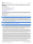
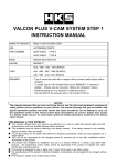
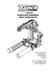
1400 EH OPERATORS HANDBOOK WD66-1400EH-M0108 Tanco Autowrap Ltd. Royal Oak Road Bagenalstown Co. Carlow Ireland Tel.: +353 (0)5997 21336 Fax: +353 (0)5997 21560 E-Mail: [email protected] T anco Autowrap 1400 Operator's manual GUARANTEE Subject to hereunder provided, the sellers undertake to correct either by repair or at their election by replacement any defect of material or workmanship which occurs in any of its goods within twelve months after delivery of such goods to frrst user, with the exception of contractors or commercial users when warranty period is six months. In respect of Autowraps the warranty period is for 12 months or 8000 bales, whichever occurs frrst. The term goods when used in this document means the article or articles described in invoices as sold by the sellers but dose not include equipment or proprietary parts or accessories not manufactured by the sellers. The sellers, however, undertake to pass on so far as they legally can to the frrst user the benefit of any warranty given to the sellers by the suppliers of such equipment, parts or accessories. This understanding shall not apply to: (a) Any goods that have been sold by the frrst user. (b) Any goods which have been injured by unfair wear and tear, neglect or improper use. (c) Any goods the identification marks of which have been altered or removed. (d) Any goods that have not received the basic normal maintenance such as tightening of bolts, nuts, tines, hose connections and fittings and normal lubrication with the recommended lubricant. The use of any product on tractors exceeding the recommended horsepower. (e) (t) Any goods that have been altered or repaired other that on instruction or with the written approval of the seller or to which any part not manufactured or having written approval by the sellers have been fixed. (g) Any second-hand goods or parts thereof. Any allegedly defective part or parts returned to the seller must be sent carriage paid. No claim for repair or replacement will be entertained unless upon discovery of the alleged defect written notification is sent to the Sellers giving, at the same time, the name of the Buyer from whom the goods were purchased and the date of purchase, together with the full details of the alleged defect and the circumstances involved, also the serial number of the machine etc. The sellers shall be under no liability to their Buyers and frrst or subsequent users of their goods or to any other person or persons for lOss or damage howsoever arising in respect of either personal injuries or for arising out of, or in any other way connected with or arising from the manufactures sale, handling, repair, maintenance, replacement or use of its goods or the failure or malfunction of any of its goods. Representation and/or warranties made by any persons (including Buyers and employees and other representatives of the Seller) which are inconsistent or conflicting with these conditions are not binding upon the sellers unless given in writing and signed by a director of sales. CLAIMS If you wish to make a claim under the guarantee: 1: Immediately, stop using the machine. 2: Consult with your Tanco dealer (supplier). He/She can download a warranty claim form on-line. This should be filled out and e-mailed to distributor and forwarded to relevant contact person in Tanco. Please ensure all relevant information is included on this form 3: Consult with your Tanco dealer (supplier) and have him forward your claim and the damaged item to Tanco. 2 Tanco Autowrap 1400 Operator's manual USER'S MANUAL TANCO AUTOWRAP 1400 CHAP. CONTENTS PAGE 1.0 INTRODUCTION 5 2.0 SAFETY PRECAUTIONS 6 3.0 GENERAL INFORMATION ON BALEWRAPPING 9 4.0 SETTING UP I MOUNTING OF THE MACHINE 11 5.0 EMERGENCY STOP* (Instant stop) 14 6.0 MOUNTING OF PLASTIC FILM 15 7.0 CONTROLLER MANUAL 17 8.0 SPEED SETTING OF THE WRAPPING ARM 23 9.0 ADJUSTING THE OVERLAP 24 10.0 OPERATING INSTRUCTIONS 25 11.0 PERIODIC MAINTENANCE 27 12.0 ELECTRIC CIRCUIT 28 13.0 DESCRIPTION OF HYDRAULICS 30 14.0 CHECK POINTS BEFORE TROUBLE SHOOTING 32 15.0 PROCEDURE OF TROUBLE SHOOTING 33 16.0 TROUBLESHOOTING 34 17.0 HYDRAULIC CHART 35 18.0 DECLARATION OF CONFORMITY 36 3 Tanco Autowrap 1400 Operator's manual TANCO AUTOWRAP 1400 Bale wrapping machine 3 1. 2. 3. 4. 5. 6. 7 8 9 10 11 Wrapping arm motor Wrapping arm Dispenser Rollers Squeeze arm Cutter 4 Chassis Drawbar Parking Stand Film Carrier Emergency stop* Taneo Autowrap 1400 Operator's manual 1.0 INTRODUCTION. Tanco Autowrap Ltd congratulates you with the choice of TANCO AUTOWRAP bale wrapping machine. We are certain you will be satisfied with the machine, and that you will have the pleasure of your investment for many years. The TANCO AUTOWRAP 1400 is an efficient, high capacity bale wrapping machine. Its low centre of gravity and unique split table design ensures that power consumption is kept to a minimum without compromising output. This system is protected by patent laws. TANCO AUTOWRAP 1400 is hydraulically driven by the tractors hydraulic system, and is controlled from the tractor cab by an automatic control unit. The machine is trailed directly behind the tractor for transport and offset to the right for working in the field. It loads the bale on the wrapping table in the same direction as it is discharged from the baler. The wrapped bale can be either dropped conventionally to the ground or with the fitting of an optional 'End Tip Ramp the bale can be dropped on its end. TANCO AUTOWRAP 1400 is designed to wrap bales of grass, hay or straw, with nominal diameter of 1.1-1.5 m, and weights up to (1400kg). The machine was developed and has been improved since it's beginning in 2008, and is now a very reliable and safe machine with high security built in. This manual is meant to explain how TANCO AUTOWRAP 1400 is prepared, attached to tractor, used and how it works, and shall together with the spare part's list be a reference for maintenance and troubleshooting. So take good care of this book, it is a part of the machine. Read carefully through this manual, and specially chapter 2.0, safety instructions, before starting the machine, and follow the instructions thoroughly. If problems should occur, check with chapter 16.0, and try to find out what is wrong. Ask your dealer for advice before you make the problem worse than it is. * EMERGENCY STOP. Tanco Autowrap 1400 is equipped with a so-called emergency stop on the wrapping arm. This device stops all functions momentarily, but is per definition not an emergency stop, because it does not shut down the inputs. But it has the same function, so we have decided to call it an emergency stop in this manual. Technical Specifications AUTOWRAP 1400 Height Width Length, min. Weight Wrapping arm speed, recommended Wrapping arm speed, max. Bale size, max. Bale weight, max. Pre-stretchers Hydraulic connection Oil pressure I amount, min. Oil amount, max. Counter pressure, max. Electric connection 2710 mm 2660mm 3940 mm 1250 kg 30 revolutions' per minute 35 revolutions' per minute 1500 m m Diameter 1400 kg 750mm 1 pcs. single working, + free return 180 bar /30 liters per minute 60 liters per minute 10 bar 12VDC Tanco Autowrap Ltd can change the construction and/or technical specifications without warning and without rights to changes on already delivered products. © Copyright. All rights reserved. Any copying and reproduction of this manual is not permitted without permission from Tanco Autowrap Ltd. With precaution of printing failure. 5 Tanco Autowrap 1400 Operator's manual 2.0 SAFETY PRECAUTIONS. Tanco Autowrap Ltd does not take responsibility for damages that may occur to machine, persons or other equipment, because of the machine NOT being used as described in this manual, or because of the safety precautions NOT being followed. 2.1 SAFETY EQUIPMENT. Before using the machine, make sure that all guards and covers are securely fitted. The machine must not be operated if a function does not work as described later in this manual. (See chapter 2.5). 2.2 BECOME FAMILIAR WITH THE OPERATIONS OF THE MACHINE. If you are unsure how to operate the machine properly, either use of or maintenance to your Tanco autowrap, please contact your Tanco autowrap dealer. 2.3 ADJUSTMENTS I MAINTENANCE. Turn off the tractor and discharge the oil pressure before performing any adjustment or maintenance on the machine. Remember that a well maintained machine is a safe machine. 2.4 IMPORTANT! ALWAYS MAKE SURE THAT NOBODY IS IN THE HAZARD AREA OF THE WRAPPING ARM WHEN THE MACHINE IS IN USE (fig 2-1). THE MACHINE MUST NEVER BE OPERATED BY PERSONS WHO DO NOT KNOW ENOUGH ABOUT HOW TO SAFELY OPERATE THE MACHINE, OR BY PERSONS LINDER 16 YEARS OF AGE. Fig.: 2-1 6 Tanco Autowrap 1400 Operator's manual Fig.M! 2.5 DANGEROUS AREAS. Tanco Autowrap Ltd has given the safety to the operator the highest priority, but it is still impossible to secure oneself of every danger area on the machine. Therefore we will now go through some of the dangers that can occur when using the Tanco autowrap bale wrapper. 1. IMPACT OF THE WRAPPING ARM. During the wrapping process the arm rotates with a speed of 30-35 revolutions per minute around the bale. On the arm is mounted a Film dispenser unit with a plastic roll. The speed on this can give a person serious injuries if one enters the working area of the wrapping arm. To reduce this danger we have mounted an emergency stop* device on the wrapping arm, this stops all movement when something comes in the way of it. It is very important that this protection always works and that it should not under any circumstances be disconnected. (See more about the emergency stop* in chapter 5.0). 2. SQUEEZE-DANGER BETWEEN THE MAIN FRAME AND THE WRAPPING ARM. As earlier explained, we have a wrapping arm with a Dispenser and a plastic roll. During every revolution the wrapping arm passes the main frame. Here there may occur a squeeze danger if a person stands to close to the main frame when the wrapping arm passes. The distance between the main frame and the wrapping arm is not large enough to give place for a person. Between the pre-stretcher and the bottom frame there can also be a squeeze danger. 3. SQUEEZE-DANGER BETWEEN THE STATIONARY AND WRAPPING ARM. During the main wrapping process the wrapping arm moves around a stationary arm. Every time the wrapping arm passes the stationary arm, there is a squeeze danger that can be dangerous for the fingers. The distance between the stationary and the wrapping arm is between 25-40 mm. (See fig. 2-2). 4. IMPACT OF BALE SQUEEZE ARM During the bale loading process the bale squeeze arm moves both vertically and horizontally. Beware of the danger. Keep clear of this area. 7 Tanco Autowrap 1400 Operator's manual 5. IMPACT DANGER WHEN MACHINE IS BEING CHANGED FROM TRANSPORT TO WORKING POSITION DRWBAR When the machine is being changed from transport to the working position it rotates out to the right and when it is being put back into transport it rotates back to the left. Beware of the danger especially if the squeeze arm is in the open position. Keep clear of this area. 6. SQUEEZE DANGER CAUSED BY PLASTIC AUTOMATION. At the end of the wrapping process the plastic is cut and held tight until the start of the next wrapping process. When the cutter arm moves down to lock the plastic, there can occur a squeeze danger between the cutter arm and the cutter holder. The cutter blade that cuts the plastic is very sharp, so keep hands away from the cutter. (See fig. 2-3). 2.6 LOCKING THE WRAPPING ARM. When the machine is not in use, make sure the locking stay for the wrapping arm is secured, and that the locking bolt is fitted. If the locking stay is not secured, the wrapping arm and/or the machine could be damaged during transport. 2.7 THREE POINT MOUNTING. When the machine is mounted on the three point linkage, make sure that the lifting arms are tightened up so there is no sideways movement. Connecting heavy working implements often has an overall negative effect on the tractor's driving and braking capacity. 2.9 TRANSPORTING. When transporting on a public road there are certain safety measures that must be taken: 1. Make sure that the machine is in the transport position. (Chapter 2.6). 2. Make sure the squeeze arm is fully closed. 3. Make sure that the wrapping arm is not parked overhanging the sides of the machine. 4. Make sure that the lights are connected and functioning correctly 5. It is recommended that the film rolls be taken off the dispensers for road transport and put on the film carriers on the drawbar. This reduces stress on the machine and reduces the danger of the rolls being accidently falling off on the public road. 6. The machine is wide (2660mm) even in transport position, be aware of this especially on narrow roads. 8 Tanco Autowrap 1400 Operator's manual 3.0 GENERAL INFORMATION ON BALE WRAPPING. 3.1 THE PRINCIPLE. The advantages of round bale silage are many, and include fewer feed units, a flexible harvesting system, large capacity and the possibility of selling feed units. In principle, the same fermentation processes occur whether the fodder is placed in a silo or pressed into bales and packed in plastic, i.e. lactic acid fermentation in anaerobic conditions. The oxygen in the bale must be exhausted before fermentation begins. The grass should be dried to approximately 30-40% solid content. The solid content can be determined by twisting the grass by hand. If drops of liquid are forced out of the grass, the solid content is less than 25%. Low solid content, (wet grass), can lead to increased butyric acid fermentation if preservatives are not added to the grass. If the solid content is too high, (over 50%), normal fermentation will not take place and there will be enough oxygen in the bale to produce mould fungus. 3.2 THE BALER. It is vital that the baler produces compact, well-formed bales, as misshapen bales can be difficult to wrap. Wrapping will also often take longer, thereby increasing the amount of plastic used. 3.3 DIFFICLILT BALES. When a misshapen bale is wrapped, it will have a tendency to move outwards or inwards on the roller. If the bale begins to move outwards, the machine must be lifted slightly at the rear edge to get the bale to rest against the support roller on the main frame. It can therefore be useful to use a hydraulic top link to make this adjustment easier. (See chapter 4.2). If the support roller almost disappears into the bale the machine should be pressed down slightly at the rear edge in order to remove the bale from the machine. The plastiC can be damaged when friction against the roller increases. Best results are achieved when the bale rolls easily against the support roller all the time. If the bale to be wrapped is conical you must ensure that the sharp end is pointed at the tractor. It will then be easier to get the bale to lie correctly during packing. It is easy for such a bale to "turn" forward in the direction in which it is pointing, and therefore lie against the support rollers. If the bale is lying on a slope it must be picked up from the lower side. A hydraulic top link will again be advantageous. 3.4 TYPES OF PLASTIC. A good type of plastiC with good adhesive properties, and which is recommended for bale wrapping, must be used. The thickness of the plastic foil should be at least 25 IJ. (25/1,000 mm). In order that the plastic tightens sufficiently around the bale, it is stretched before being wrapped, so it is somewhat thinner when it is put on the bale. With short-term storage, (up to eight weeks), it is recommended that bales have a minimum of four layers of plastic at the thinnest points, with at least 52-53% overlap. For long-term storage, or when the grass is wet when it is wrapped, the bale should have 90-100 IJ plastic, (6 layers), and the same amount of overlap. If thinner plastic is used, more layers should be applied. If it is very hot the plastic will be stretched further, and more layers should be applied. It is better to have slightly too much than too little plastic on the bale. From experience, light colored plastic produces slightly lower temperatures within the bale, and tends to improve feed quality. 9 Taneo Autowrap 1400 Operator's manual 3.5 STORAGE LOCATION. Care should be taken in finding a suitable location for the storage of bales. The storage location should preferably be prepared before the bales are laid out. An elevation close to well-drained roads is recommended. If the wrapped bales are simply placed on stubble there is a danger of the plastic being pier.ced. A tarpaulin or a thin layer of sand should therefore be laid where the bales are to be stored over the winter. Bales should be stored in the shade as far as possible. This reduces the danger of air leakage in the bales. A bale which is stored in sunlight and which therefore undergoes greater swings in temperature "pumps in" a great deal of air in comparison to a bale stored in the shade. According to 'Teknik for Lantbruket" [fechnology for Agriculture] in Sweden, a bale stored in the shade has only 40% of the air leakage of a bale which is stored in sunlight. 3.6 STACKING I PROTECTION. If bales are hard and well formed, they can be stacked vertically, but loose and misshapen bales with low solid content should not be stacked higher than one layer, as this could easily cause deformity and the danger of runoff will be increased. Bales can also be stored on their sides. The layer of plastic is thicker here, providing greater protection against piercing. Bales should be covered with a tarpaulin or a fine-mesh net to protect against birds and small rodents. If the plastic is pierced, it must be sealed with weatherproof, hard-wearing tape, preferably under the outermost layer of plastic. Ensure that the hole is adequately sealed. 3.7 The best wrapping results are obtained by... ... harvesting the grass early. ...drying it out to 30-40% solid content. If there is a danger of rain, bale and wrap the grass anyway. ...taking care not to mix any earth in with the grass . ...using a baler that produces even, firm bales. Bales 1.2 m in width and with a diameter of 1.2-1.5 m are the preferred sizes . ...wrapping the bales soon after baling. never later than two hours afterwards . ...using a good plastic type and six layers of plastic. This removes the need to use preservatives . .. .storing bales in the shade to reduce the danger of air leakage. 10 Tanco Autowrap 1400 Operator's manual 4.0 SETTING UP I MOUNTING OF THE MACHINE. Be careful! There is a danger of being crushed when working implements are fitted and connected. Carry out the fitting procedures slowly and carefully, and use separate and approved lifting equipment to make the work easier. See section 2 on safety regulations and pay attention to the various safety decals displayed on different parts of the bale wrapper. 4.1 ATTACHING TO TRACTOR The 1400 can be either connected to the tractor lower links using linkage attachment (4) or by removing this it can be attached to the tractor hitch. If the lower link bracket is used the hitch eye (6) should be attached in the lowest position, this will allow greater movement. If attached to the tractor hitch it is recommended that the machine is attached to the clevis hitch rather than the pick up hitch. This gives more clearance between the drawbar and the tractor back wheels. The drawbar does not run directly behind the tractor. In transport the drawbar runs nearer the left wheel so the minimum turning circle to the left is reduced. In the working position this is the case for turning to the right. When the machine is attached to the tractor the stand leg (2) must be folded up to the drawbar by removing the pin (1), swing up the stand leg and fit the pin in Pos. B. (Fig 4-1) 4.2 HITCH HEIGHT Fig.: 4-1 When attached to the tractor the machine should sit level, at this the squeeze arm will have 10cm approx. clearance with the ground when in the fully lowered position. Set linkage height to achieve this. Adjust the linkage stabilizers to limit the lateral movement. If attached to the hitch change the hitch eye mounting position to set the correct height. Make sure the hitch eye fixing bolts (6) are securely tightened. 11 Tanco Autowrap 1400 Operator's manual 4.3 CONTROL BOX 1400 1400 Controller 4.4 ELECTRIC CONNECTION. The electric supply for the machine's remote control and electro-hydraulic components must come directly from the tractors' 12 volt battery. 2 The electric wires from the battery must have an area measurement of min. 2,5 mm • Connection to other contacts on the tractor can cause risk of malfunction, and is not recommended. BROWN LEADER GOES TO BATTERY PLUS POLE BLUE LEADER GOES TO BATTERY MINUS POLE 4.5 CONTROL BOX 1400. The control unit consists of the emergency stop button, a control cable, a fuse and a battery cable. The control unit should be attached to a suitable place in the tractor cab. THE REMOTE CONTROL UNIT IS NOT SHOCK-PROOF. MAKE SURE THAT IT IS FASTENED TO A SOFT PAD THAT SECURES A NON-VIBRATING FOUNDATION. 4.6 HYDRAULIC CONNECTION. The hydraulic hoses between machine and tractor are equipped with 1/2" ISO male quick couplers. Discharge the oil pressure before you connect the oil hoses. Use the tractors' hydraulic lever. To make sure that the bale wrapper works properly, the tractors' oil pressure has to be at least 180 bar. The oil flow should be 15 - 25 liters per minute. The return pressure on the return must be as low as possible, and not exceed 10 bar. This should be measured with a gauge. It is recommended to use one single-working hydraulic outlet and arrange a free return circuit to the oil tank. If you are unsure of what oil pressure the tractor gives, or what oil pressure the bale wrapper receives, please contact your machinery dealer. Generally 12 Tanco Autowrap 1400 Operator's manual all tractors have got some counter-pressure in their hydraulic return systems. Some tractors have more than others. Hose with red cap shall be connected to pressure, (P), and hose with blue cap to the return. (T). 4.7 OPEN and CLOSED CENTER and LS HYDRAULIC SYSTEM. The 1400 hydraulic system can be set up for tractors with open or closed center hydraulics Open Centre Hydraulics Most tractors have a hydraulic system that gives a continuous output which flows through the valve on the machine and back to tank when no function is operating. (Open center). TANCO AUTOWRAP 1400 is set-up for open centre on leaving the factory. Close Centre Hydraulics Some tractors, (like John Deere), have a hydraulic system that require the valve on the machine to allow no flow when no function is operating (Closed center). The hydraulic valve can easily be contjgured to operate in this way. Simply push and twist the manual override onthe master valve. (see fig 4.2) Push and f\.vist to lock for Closed Centre Fig. 4.2 LS Hydraulics Many modern tractors have a "Load Sensing" (LS) hydraulic system. This is most efficient as the pump remains on standby, pl,.lmping no oil until it gets a signal from the machine. It is possible to run this machine on a load sensing tractor with the standard valve. Configure the valve for open centers and if possible adjust the flow from the tractor to give -30 I/min. This however means that that tractor is constantly pumping and you do not get the benefit of the efficiency of your load sensing pump. Thus Tanco Autowrap strongly recommend that if you are running the machine on tractor with LS hydraulics you should fit the optional load-sensing block (see hydraulic circuit). With this block fitted a Load sensing signal is transmitted in the form of hydraulic pressure via a hose for the LS port on the LS entry block to the LS connection on the tractor. Note that the LS entry block can be configured also to run on any other hydraulic system, open or closed center. 13 Tanco Autowrap 1400 Operator's manual 4.8 CHECK LIST. Before using the machine it is recommended to follow this check list: 1. Make it a habit to discharge the oil-pressure before connection or disconnection of the hydraulic hoses. (By operating the hydraulic control lever inside the tractor). (Use the tractors hydraulic control lever). 2. Return-oil should be led directly to tank. Beware that if the counter pressure is too high, the security valve on the main block will release some oil. (See chapter 13). 3. Hose with BLUE CAP 4. Hose with RED CAP 5. Tie up loose hoses and Connection Cables so that no squeeze damages occur. 6. Remove the locking bolt that holds the wrapping arm to the frame during transport. 7. Start the tractor and try out the functions. A bale is not required for this test. 8. Check all connections, hoses and couplings. If there is any oil-leakage, it should be rectified immediately. =RETURN OIL. =PRESSURE. If any problems should occur, it is most likely that the failure is in the quick-couplers on the tractors pressure and return-connections. Make sure that both the male and the female-couplers opens properly for the oil flow. Check them carefully. The best thing to do is to exchange the quick-coupling on the return side and arrange a "free return". Your TANCO AUTOWRAP bale wrapper has been tested in practical operation in approx. 2 hours at the factory. 14 Tanco Autowrap 1400 Operator's manual 5.0 EMERGENCY STOP*. 5.1 The machine is equipped with a safety guards on the wrapping arms, and its operation must be tested before work itself is started. 5.2 The emergency stop* is to prevent the wrapping arm from damaging people and objects, when the machine is started and during the wrapping process. 5.3 It consists of a safety arm that activates a small electric switch, which gives a signal to the control box to start the emergency stop. 5.4 When testing this function, start the wrapping arm. Hold out an arm or any obstacle. The wrapping arm shall now stop before it hits the arm. Great care must be taken when testing this function. To restart the machine the obstacle must be removed and the arm must be returned to its original position. The Auto switch on the control box must be activated again. The wrapping may start again. 5.5 IMPORTANT: GIVEN THE VELOCITY AND MOMENTUM OF THE ARM IT IS IMPOSSIBLE TO STOP THE WRAP ARM IMMEDIATELY. THE EMERGENCY STOP ARM IS PROVIDED TO HELP REDUCE THE RISK OF SERIOUS INJURY AND GREAT CARE MUST BE TAKEN WHEN OPERATING THIS MACHINE. 6.0 MOUNTING OF PLASTIC FILM. Fig.: 6-1 • Fig.: 6-2 When loading a plastiC roll, first ensure the top cone (2) is pushed up to latched position, then push back the Stretch rollers (3) until held in position by locking catch (4) .. • Place the Roll on the Bottom Cone and release the top latch (1). Beware of Fingers! • Pull the film between the rollers on the pre-stretcher in the direction of the arrow. (See fig. 6-2). (See also the sticker on the dispenser). • Release the locking catch and allow the rollers to lie against the roll of film. Pull the film from the roll and tie it to the bale. 6.1 The standard film dispenser is designed for 750mm film. 15 Tanco Autowrap 1400 Operator's manual Fig.: 6-3 Fig.: 6-4 6.2 Height adjustment of pre-stretcher I plastic film. The plastic film should hit at the middle of the bale wrapped (fig 6-3), and therefore it can be necessary to adjust the height of the pre-stretcher (fig. 6-4). 6.3 Tanco Dual Stretch Dispenser All Tanco Autowrap machines are supplied with a patented dual stretch gear system. This system enables a quick change of stretch levels on the Film Dispenser. If the bolt (1) is fitted in position 2, the top set of gears provide the stretch (70%). 16 Taneo Autowrap 1400 Operator's manual By removing the bolt from position 2 and fitting it in position 3, the bottom set of gears become the stretch gears giving 32% (for prestretched film) or optionally 55% (for use in hotter climates or with square bales). Tanco Dispenser Gear Cornbinations % Stretch Inner Gear Outer Gear 60 Tooth 35 Tooth 70% 58 Tooth 37 Tooth 550/0 54 Tooth 41 Tooth 32% 17 Tanco Autowrap 1400 Operator's manual 7.0 EH Controller Manual Contents 1. INTRODUCTION 1.1 IMPORTANT SAFETY INFORMATION! 1.2 Main operating Functions and Display 2. OPERATION 2.1 Operation in Automatic mode 2.20peration in Manual mode 2.3 Manual options in Automatic mode 2.40perations in Manual mode 2.5 The Display Menu 2.6Selecting a Store Total 2.7 Resetting a Store Total to Zero 2.BSetting the Number of Wraps 2.9 Film Break Alarm (Optional) 3 OPERATOR SETUP MENU 18 Tanco Autowrap 1400 Operator's manual 1. Introduction The Tanco Autowrap Bale Wrap Controller enables the operator to monitor and control the operation of the bale wrapper at any stage of the wrapping cycle. The controller is designed for models: 1400 and 1814 table type wrappers. There are 2 operating modes - Automatic and Manual. The automatic mode permits 'one-touch wrapping' to ease the workload on the operator. The controller is fully programmable to optimise wrapping performance. Bale counts are automatically logged in anyone of 10 selectable memory stores, in addition to a grand total memory store. 1.1 IMPORTANT SAFETY INFORMATION! &: Please read and understand the instructions for using this controller before operating the machine. This controller is fitted with a pushbutton type On/Off Emergency Stop switch. Always ensure the controller is switched OFF via this switch before attempting any adjustment or maintenance to the machine. • Please follow ALL other safety instructions given in the manufacturers' Operator Handbook for this machine. 1.2 Main operating Functions and Display The principal instrument features and operating functions are shown in figure 1 below. [Figure 11· A 2-line, 32 character dot matrix, back-lit display shows in the normal operating mode: Current No. ofwraps Target No. of wraps Wrapping speed (rpm) Bale total (10 separate stores) Grand Total No. ofbales Mode CM' - manual, 'A' Auto) 4-way Menu switch to • • • • Set No. of wraps Change/reset bale SUb-total Access Operator Setup menu Access Technician Setup menu Move drawbar to working position Release fIlm grip Fast wrap I Resume wrap after manually pausing Add 1 wrap to: current or next Reverse wrap arm Bale Offload M(mode): Tips bale A(mode): Starts Auto Offload: bale, lowers front to load returns rear roller to working position. Automatic Wrapping Press STOP switch to L6 19 , Tanco Autowrap 1400 Operator's manual In M In M (mode): Load Up (mode): Load down Auto Hand Cont. ON (See 2.1) Auto Hand Cont. ON (See 2.1) In A (mode): starts Autoload In A (mode): starts Auto Offload In M (mode): Squeeze Out In Auto Hand Cont. ON M (mode): Squeeze In (See 2.1) InA (mode): starts Auto Wrap Hand held controller 2 2.1 Operation Operation in Automatic mode The automatic sequence is made up of three sections: Loading, Wrapping and Offloading. The controller comes initially set so one press of a button automatically loads the bale, a second press runs the complete wrapping cycle and a third press automatically offloads the bale. It is possible to set the controller so one button press runs the com plete cycle, see section 2.1.2. As initially set three buttons on the controller are used to start each section of the sequence, see points, 3, 5, and 7 below. If in the Operator Setup Auto Hand Cont. is changed from Off to On then three buttons on the hand controller can be used to start the sections of the sequence. See diagram above. The controller will have to be changed from Auto A to Manual M mode for the hand controller to operate their original load arm functions. 1. 'A' on the display indicates that the controller is set in Automatic mode. If not, press to select. ~ (L6) 2. The automatic starts with the wrap arm in the park position, that is with the wrap arm magnet parked under the sensor, the load arm down and squeeze arm in the fully open position. See 10.1 3. Press the switch.~ (L5) to start the Autoload sequence as follows: The squeeze arm comes in for a set time, bringing it in under the bale The load arm raises for a set time, lifting the bale on to the table. The squeeze arm opens fully to a sensor. 4. If the wrapping arm is not parked in the Park position then the controller will give an error message DISPENSER POSN. and it will not start loading. Correct the arm position and repeat. e 5. Press the (R6) switch to commence the automatic wrapping cycle as follows: The wrap ann will start in slow speed, ramp up to full speed. The Cut and Starts open twice to release the plastic. On the last turn the wrap arm ramps -down to slow speed. The Cut and· Starts open. The wrap arm stops. The Cut and Start closes. The wrap arm reverses to the park position. 20 Tanco Autowrap 1400 Operator's manual 6. The squeeze arm must be in the fully out position for auto wrapping to start, if it is not the controller will give an error message SQUEEZE OUT and not start wrapping. Correct the squeeze arm position and repeat. 7. Press the switch ~ (R5) (AUTO) to start the Auto Off-Load 8. If the wrapping arm is not stopped in the park position then the controller will give an error message DISPENSER POSN. and IT will not start Auto Off-load. Correct the arm position and repeat. 2.1.2 Changing default automatic sequence. In the default automatic sequence the controller waits for a start signal before wrapping and again before offioading. It is possible to change this: In the Operator Setup if Autostart Wrap setting is changed from Off to On, then wrapping will automatically start when the load sequence has finished. Likewise if Auto Off-Load is change to On then the bale will automatically be offioaded when the wrapping sequence has finished. Great care should be taken when auto offioading especially in hilly conditions. In the interest of safety if the above settings are set to On, the controller will prompt you to confirm the On setting if the controller is switched off and on again. 2.2 Manually interrupting an automatic wrapping cycle ~ Press the (L3) button to bring the wrapper to a controlled stop. Pressing the lRE;E) (R3) switch ' " will resume the auto-wrap cycle from where it stopped. ~ For safety reasons, if it is necessary to work on the machine (e.g. in the event of a film break or the film running out), then it is strongly recommended that you then switch the controller offvia the red stop button .. and disengage the machine power source. Pressing the (R~EJ (R3) switch after switching the controller back on will resume the auto-wrap cycle from where it stopped. Unless it is an emergency situation, do not bring the machine to a stop by pressing the red stop button as this will impose unnecessary strain on the machine. 2.3 Manual options in Automatic mode With the controller in automatic mode, the following manual functions are possible . . . SLOW WRAP (not during the wrapping sequence). If this button is held down the arm will stop when it comes to the park position. see fig. 10.3.1 .. Releasing and pressing again will move the arm to the next park position. ~ Press ,j"'l (R3) to resume the normal fast wrap . - . . REVERSE WRAP ARM (only enabled outside of the wrapping sequence). Press this button to . nudge the wrap arm backwards to the desired position. As with the slow wrap if this button is held down the arm will stop at the park position. LOAD ARM UP mode) (on hand held controller) raises load arm. (See 2.1.2 for options in Auto 21 Taneo Autowrap 1400 Operator's manual LOAD ARM DOWN (on hand held controller) lowers the load arm. (See 2.1.2 for options in Auto mode) ~ (on hand held controller) closes squeeze arm in. SQUEEZE ARM OUT ~ (on hand held controller) opens squeeze arm (See 2.1.2 for options in SQUEEZE ARM IN Auto mode) +1 ADD 1 WRAP Each time you press this button an additional wrap will be put on the current bale if the wrapping sequence is in progress, or onto the next bale if the automatic cycle has not yet been started. You can add as many wraps as required. 2.4 2.5 Operation in Manual mode 'M' on the display indicates that the controller is set in manual mode. If not, press ~ to select. In manual mode you have total control of every stage of the wrapping cycle. The software logic determines which manual functions can be activated at any point in the wrapping cycle. Should the operator incorrectly select a function at a certain stage during the wrapping cycle, then that operation will not be performed. The Display Menu The Display menu is divided into 3 sections. At the top level are the settings used during the daily work with the machine - i.e. Store totals and No. of Wraps. The Operator Setup' section enables the operator to perform adjustments to the machine operation - e.g. time duration and time delay settings during the automatic cycle. The Technician Setup' menu is not normally accessible to the operator without a PIN access code. Technician Setup' is not covered by this manual. Use the 4-way switch to navigate the menu. Each menu screen indicates which keys to press to make the settings. The instrument will default back to the main operating display after 30 seconds if no other key is pressed Here is a summary of the display menu; Default display TOTAL A o o '--_ _ _ _ _ _.. A,B,C,D,E, F,G,H.I.J Use ........J to Set 16 ' - - - - - - - . . . . 0 - 99 See PROGRAMMING FACTORS ON PAGE Section 7.3 Tanco Autowrap 1400 . Operator's manual NOTE: There are additional sequences selectable in the Operator Setup menu but not shown in the table. These sequences are for wrapper models to which this manual does not apply. Please refer to section 3 for further explanation of the Operator Setup functions given in the table above. 2.6 Selecting a Store Total There are 10 individual memory registers labeled 'Store A' to 'Store J' for bale totals. Each time a bale cycle is completed, the currently selected store total and the grand total increments by 1. The currently selected store is displayed on one of the two screens selectable in the normal operating mode . • WRAPS ~ 0-16 M ° RPM 12.1V I+---I~ '--..::.....;.-=-----"';~-~r The default setting is Store A. To select a particular store, navigate the display menu using the 4 way switch. o RPM ! 12.1V i ~~~~----~!ESC ! ° .J L.......:-=.:::::..:,.:._ _ _ _0::...J '--_ _ _ _ _--1~A,B.C,D,E, F,G,H,I,J Press the up/down arrow keys to select the store, then press the ENTER key to confirm the selection. 2.7 Resetting a Store Total to Zero Stores A to J can be individually reset to zero at any time. The Grand Total store cannot be reset. First select the store to be zeroed, and then navigate the display menu as shown below. • T Total A (.J to Reset) ° Press the ENTER key to reset. 23 Tanco Autowrap 1400 Operator's manual 2.8 Setting the Number of Wraps The default number of wraps is 16. You can set the target number from 0 to 99 by navigating the display menu as shown below. 0-99 24 Tanco Autowrap 1400 Operator's manual 3 Operator Setup Menu The default settings for the machine are developed by Tanco for optimal operation of the machine. However, the operator can change certain parameters in the 'Operator Setup' menu to take account of operational conditions. Programmable Factors - 1400 Software revision 312-020 Target number 25 8.0 Transport and working positions Working in the field the 1400 is off set to the right had side of the tractor for road transport the draw bar is moved in so the machine runs directly behind the tractor. 8.1 To change from working to transport position: See fig. 8.1 Swing draw (1) bar in fully. Raise the load arm (2) fully up. Rotate wrap arm (4) in slow speed to so it is running in line with the centre of the machine, it is recommended for safety that the rolls of film be removed from the dispensers and placed on the carriers on the drawbar. Rotate the squeeze arm (3) to its inner position taking care that the not strike the parked wrap arm. 8.2 To move from transport to working.sition carry out the above in reverse order. Note If Wrap Arm Reverse button _ is held down the wrap arm will reverse to the park position and stop automatically in the correct position. Fig. 8.1 26 8.0 8.1.1 SPEED-SETIING OF THE WRAPPING ARM. The wrapping arm speed is controlled by a proportional hydraulic valve. When running in automatic mode the arm starts at slow speed. then ramps to full speed and on the last revolution ramps down to slow and stop. The machine is set as standard to run at approximately 30 RPM. Adjustment of arm speed is done in the Technician Level of the controller and it is therefore recommended that it be altered by an experienced technician. Menu No.5.4 Fast Arm PWM, sets the maximum arm speed. Note the setting valve here in not the actual RPM but the proportion the valve is open. A setting of 50 equates to 30 RPM approx. Note setting changes should only be made in increments of 1 as the maximum allowable speed is 32 RPM. Slow speed and ramping up and down settings are also done in the technician Level of the controller NOTE: Max. allowed wrapping arm speed is 32 revolutions per minute. REMEMBER! Increased speed of tractor engine does not increase the wrapping speed, it only increases the oil flow into the system, this may increase the temperature in the hydraulic system. 27 Fig. 9-1 9.0 ADJUSTING THE OVERLAP. 9.1 OVERLAPPING. The 1400 is fitted as standard with the 2 x 2 x 50% film overlap system when using 2 rolls of750 film. This is achieved by means of the gear ratio of the drive, ensure that the correct number of film layers are applied to the bale after a specific number of revolutions of the wrap arm. The number of turns required to wrap a bale depends on bale size To calculate the number of turns required: Count the number of turns to just cover the bale, add 1 to this. This applies two layers, multiply by 2 for 4 layers, 3 for 6 layers and so on. The table below give an indication of the number of wraps to achieve the desired number of layers on different size bales. Best practice suggests a minimum of 6 layers and more on high dry matter and stemmy material. Bale Diameter 4 Layers 6 Layers 120cm 150cm 16 wraps 20 wraps 24 wraps 30 wraps 28 10.0 OPERATING INSTRUCTIONS. We shall now go through a complete wrapping process, from loading to storage place, and explain the practical use of Tanco Autowrap 1400. 10.1 • LOADING. When loading a plastic roll, first ensure the top cone (2) is pushed up to latched position, then push back the Stretch rollers (3) until held in position by locking catch (4). • Place the Roll on the Bottom Cone and release the top latch (1). • Pull the film between the rollers on the pre-stretcher in the direction of the arrow. (See fig. 5-2). (See also the sticker on the dispenser). • • 10.2 Release the locking catch and allow the rollers to lie against the roll offilm. Pull the film from the roll and tie it to the bale. Controller Automation Setting. The controller allows for varying degrees of operator intervention in the control of the machine. It is possible to set the controller so one press of a button will run a full automatic sequence from loading to wrapping and unloading. (See Controller Manual Section 7.) When operating in less than ideal conditions for example when wrapping badly shaped bales or if wrapping in hilly areas it is advisable to break the sequence into the three sections of loading, wrapping and unloading. 29 10.3 LOADING. Set the machine into the loading position: (See fig. 10.3.2) • Move the drawbar (1) to the full out position. • Lower the load arm (2) to the ground. • Open the squeeze arm (3) fully. • Ensure the wrap arm (4) is in the park position.(wrap arm magnet positioned under sensor) See Fig 10.3.1 The controller will not allow loading if the wrap arm is not in this position. • Drive up to bale, keeping Guide plate (5) close to the end of the bale, commence loading when load arm cross tube (2) is in contact with the bale. Fig 10.3.1 Fig 10.3.2 30 10.4 Wrapping. The squeeze arm (3) must be in the full out position for wrapping to commence Make sure that the bale is sitting correctly on the table before starting wrapping. Button R6 AUTO START STARTS the automatic wrapping cycle. 10.5 STOP. In A (Auto mode) the machine will run through a full automatic wrapping sequence One round before the required number of revolutions is obtained, the speed of the wrapping arm is reduced and the cutter opens. The wrapping arm passes the open cutter and stops. The cutter closes and the wrapping arm reverses to the park position. See Section 7 for making alterations to controller settings. 10.6 Offloading Bale. The rear roller drops down to offload the bale. Beware of the danger of the bales rolling when working in hilly conditions, always off load the bale across the hill. The controller allows a number of methods of triggering offloading: If Auto Off-Load is set to ON (Operator Setup) then the bale will be automatically offloaded at the end of wrapping. If Auto Off-Load is set to OFF, then button R5 must be pressed to start offloading. 10.7 End Tipping Bale. The 1400 can be fitted with an optional bale end tipping attachment (1) which turns the bale on to its end as it is being offloaded. It is attached to the rear roller frame with bolts (2) and rubber buffers (3) can be adjusted to ensure that wheel (4) is clear of the ground when in transport. 30 o Fig 10.7 To avoid damage to the bale the 1400 should be stationary when end tipping. The terrain and the bale shape have a big bearing on the operation of the end tip attachment. The mounting height of wheel (4) is adjustable to improve operation with different bale sizes and operating conditions. 11.0 PERIODIC MAINTENANCE. 11.1 BEARINGS. All ball-bearings are packed with grease, and do not need any more maintenance. 11.2 PRE-STRETCHER. If the machine is in daily use, the Gears under the plastic cover on the dispenser should be greased when needed. 11.3 CUTTER I FILM HOLDER. The cutter I film holder is pre-adjusted from the factory and does not need further adjustments. When replacing spare parts, it is necessary to adjust it. The springs for the U-shaped slot shall be adjusted so that they are almost completely squeezed together when the cutter-arm is all down. 11.4 CLEANING. The machine should be cleaned and oiled regularly and at the end of the wrapping season. NOTE! When using high pressure washing apparatus, care must be taken with the electrical installation. Also make sure that water is not sprayed directly into the bearings, etc .. Keep the control box protected from rain and water. If necessary use compressed air to dry electrical components. 31 11.5 HYDRAULIC CYLINDERS. Make sure that all hydraulic cylinders are closed when storing the machine. 11.6 QUICK COUPLERS. Ensure that the quick couplers are kept clean and apply the dust caps after use. 11.7 STORAGE. The machine should be parked on a dry place during the closed season. 11.8 OIL FILTER. The oil filter must be changed once a year. 32 ...lo. N p (:, PINI CURRENT REGULA TOfl .fImJlI J ov Il._ 1/1' ·2 ov II/A 1/1'.J ov £-S1ttp 1/1' • ov N/A 'A' ~!/. . 1/1' A Ii ., \J,) \J,) 's' 1m' PI.2 PU PU _RGG• (") ~ ~,"'g",' ,[iii ® (") (") -I C ~ OM:l:fi:itiOtl II/A I/P ov """_I 1/1' OV Rm BrBDk 2 1 . ~ ::u (") c ov 1/1' i I m m r 1/1' OV p,.r;rt>fl<>n ~ II I N/A i 1 OV IN SI(IOV ¥A(,\£, ~ Numb", 2 + + 12V IN ...lo. :s • PWII SlG IN 5 VALlIE - 6 ~ Q Q 6"""'£_~ nUn [TTITE 6 wgy.strlp "CON 1" PCS INTERNAL WIRING eMMetot' .. to.... If U II ROLLERS STOP "3" I CON 1- 3 I CON 1- 2 DRAWSAR IN "14" MASTER VALVE 1 "4" FORWARD ROTATE "5" II....ary c.up/Ing REVERSING "13" LOAD ARM DOWN "15" CON ARM SPEED (PIVM) "5' CON SQUEEZE OUT "10" CON 1- 20 CON 1- 21 11 II 11 I I I I I 6 WIIy ..UIp .,,,,,...tor ""...,,""" LOAD UP "9" CON 1- 20 CON 1 19 C&S OPEN "1" CON 1- 25 CON 1 24 C&:S CLOSE "2 CON 1- 25 CON 1- 22 TIP RETURN "12" CON 1- 29 CON 1- 28 TIP "11" CON 1- 27 CON 1- 2Ei SQUEEZE IN H7" DRAWSAR OUT -e" CON 1- 33 CON 1 32 CON 1- 31 CON 1 30 1400 Junction Box Wiring Tanco 1814 & 1400 Junction Box Wiring Table - 27/02/2009 Tanco Generic Cable 34 There are 3 basics, which must ALWAYS be followed if the machine is to function correctly NOTE I • Free Return Max 10 bar (direct to tank) Working Pressure 185 Bar Voltage: 12 V ' - - - - - - - - - - , straight from Battery 35 13.0 DESCRIPTION OF HYDRAULICS. 13.1 General The control valve uses a 'Master Valve system, so to operate any function the master valve plus the service vale for that function is powered. For troubleshooting purposes it is useful to note on the control valve that, energizing a solenoid on top of the valve gives pressure out the bottom port of that section on valve and vice versa. "OPEN CENTER" HYDRAULICS. Most tractors have an "Open Centre" Hydraulic System which delivers a continuous oil supply. The 1300EH machine is set as standard to suit this. If no other function is activated, the oil flows from the tractor, through the main valve block and back to the tank. When a function is operated, THE MASTER VALVE (4) , closes the oil flow circuit to the return, and simultaneously the valve for the current function is opening. "CLOSED CENTER" HYDRAULICS For tractors with a "Closed Centre" hydraulic system, like John Deere the oil flow through the valve is closed when no function operating, the tractor maintains a standby pressure with no oil flow. When a function is operated oil is directed to that function. The 1400 hydraulic system is easily converted to run on closed centre hydraulics, just push in and rotate the button on the master valve (4). This locks this valve in the closed position. (Section 4.8). 36 13.2 Valves 1 to 15 are 12 volt electrical solenoid valves Their functions are as follows: Valve (1) Cutter Open. Valve (2) Cutter Close. These valves open and close the film cutter To prevent the Cutter creeping open, there is a load holding valve on top of the cutter section of the control valve. There is a 2mm speed control orifice in the bottom port of the cutter section. Valve (3) Roller Stop. This valve is normally closed, it is pulsed open and closed to give half speed on the table rollers when the film break sensor detects that one film has broken Valve (4) Master valve. This valve is powered for every function. See 13.1 Valve (5) Arm Rotate. This valve powers the wrap arm and table rollers. Valve (6) is always operated with this valve. Valve (6) Wrap Arm Speed. This valve controls the speed of the wrap arm, it gets a varying PWM (pulse wave modulation) signal from the controller to vary the speed. Its settings are adjustable in the Technician Setup in the controller Valve (7) Squeeze In. This valve powers squeeze arm in. Valve (8) Drawbar Out. This valve moves the drawbar out to the working position. Valve (9) Load up. This valve raises the load arm. Valve (10) Squeeze out. This valve opens the squeeze arm. Valve (11) Tip Down. This poppet valve mounted on the tip port of the control valve (not shown in Fig 13.1) lowers the rear roller frame for tipping off bale. Valve (12) Tip Return. This valve raises rear roller frame after tipping. Valve (13) Reversing valve. This vale mounted on the Tower Valve reverse the direction of the wrap arm. It is always oper~ted with valve (5) and (6). Valve (14) Drawbar In. This moves the drawbar in to the transport position Valve (15) Load Arm Down. This valve lowers the load arm. 37 Valves 16,17,18 are on the tower block Valve (16) (VBS) Brake valve. This is a pilot operated (8:! Ratio) load holding valve This valve regulates the oil flow on the outlet side of the wrap arm motor .It makes the arm run smoother and holds it in place when parked. Valve (17)(VMP) Cross Line Relief Valve Forward. This valve limits the max. torque of the wrapping arm. If the inlet pressure exceeds the set value, it relieves the oil across to the outlet side of the motor. It is adjusted so that the pull force on the far end of the arm is approx. 35 KG. If it is set too high acceleration at the beginning of wrapping will be very sharp. Valve (18)(VMT) Cross Line Relief Valve Reverse. This valve ensures a gradual stop for the wrap arm by limiting the pressure on the outlet side of the motor. If the pressure exceeds the set value, it relieves the oil across to the inlet side of the motor. Valve(19) Main Relief Valve. The hydraulic system is equipped with a safety relief valve, which is preset to 185 bar. If this pressure is exceeded it opens and allow the oil from the pressure port to the tank port of control valve IMPORTANT: Valves [16 to 19] have been carefully set in the factory. Incorrect adjustment of these may cause damage to the machine. Always ensure that trained personnel only adjust the settings of these valves. Pressure Test Point. There is a pressure test point on the inlet end of the control block. 38 14.0 CHECK POINTS BEFORE TROUBLE SHOOTING. In this chapter we have some general check points that have to be examined first if something is wrong with the machine. In chapter 16.0 we have a more detailed trouble shooting. There are three basic assumptions that have to be fulfilled if the machine shall function properly: 1. 2. 3. 14.1 The oil pressure from tractor should be 180 bar. The return flow of oil has to be as free as possible, max. 10 bar counter pressure. Enough electric power to all functions. OIL PRESSURE. To check the oil pressure into the machine is high enough, a gauge may be placed in line on the feed hose or there is a standard test point on the end of the control valve. OIL FLOW. The oil amount that the tractor delivers should be minimum 20 liters/minute for satisfactory operation of the machine, but it is recommended that it is 30 liters/minute. (Max. allowed oil amount is 60 liters/minute). Ensure that oil level in tractor's hydraulic system is correct and tractor's oil filter is changed regularly. 14.2 RETURN PRESSURE. High oil return pressure will MAX. ALLOWED RETURN PRESSURE IS10 BAR. We recommend "free return" directly to the tank. 14.3 ELECTRIC POWER. It is important to check that all functions receiVe enough electric power. If not, some, or all functions may fail. The controller displays a voltage reading. Is the battery voltage high enough? If the voltage falls below 10 volts the valves will not be able to open. Are the cables correctly connected to the battery? Follow directions in chapter 4.4 Is the connection between battery cable and control unit OK? Clean off the poles and check the plug. Is the connection between controller unit and machine OK? Change contacts if any doubt about the condition. Is the fuse on the battery cable OK? PLEASE CONTACT YOUR DEALER IF YOU ARE IN DOUBT ABOUT ANYTHING. (Remember always to give your dealer the serial number and production year of your machine when contacting dealer and when ordering spare parts). 39 15.0 PROCEDURE OF TROUBLE SHOOTING. If the machine fails to operate correctly it must be determined if the problem is hydraulic, mechanical or electrical. 15.1 SOLENOID VALVES. When checking if the Solenoid valves are receiving electric power, you do this in the following way: 1. 2. 3. Unscrew the nut that holds the solenoid. The solenoid is easy to move without electric power. Push the current function on the remote control. If the solenoid gets power, it will be difficult to move, it "sticks". This is the best and easiest way to check if the solenoid valve is receiving electric power. Another way is to hold a screwdriver up to the magnet. If it "sticks", the solenoid is receiving electric power. The power supply to the valve can also be measured with a voltmeter, but then the contact must be connected to the solenoid, so it is using power. To have reliable functions, the voltage should not be lower than 11,5 volts, even if the solenoid valve usually works with a little lower voltage. 15.2 Only for solenoid valves to the main functions. If the electric supply is in order and one of the functions fails, the reason can be dirt that tightens or prevents the sliding shaft (spool) from moving. Try to maneuver the function manually, by pressing the point of a screwdriver into the end of the valve housing. At the same time the corresponding switch on the control unit has to be operated to get electric power to the master valve. If the. function is working again after this, the dirt may have been pushed out in the oil system and the machine can be operated normally again. Take care so that the machines moving parts, do not cause damage to persons or objects. 40 16.0 TROUBLE SHOOTING. 16.1 THE MACHINE DOES NOT FUNCTION. a) Even if the gauge shows enough pressure and there is no reaction in the machine. The reason could be that one, (or both). of the quick-couplers does not open for the oil. Change quick couplers. b) The counter pressure could be too high. Max. allowed counter pressure is 10 bar. (See chapter 14). c) Make sure that the open I closed valve is correctly positioned. (Disturbances of this type, a, b or c, are most likely in the first days that the machine is in use). 16.3 THE CUTTER WILL NOT HOLD THE FILM. Is the cutter closing fully, if not increase the Cutter Close Duration 2. (See chapter 6.3) If the cutter creeping open, there may be dirt in the load holding, open and close the cutter a number of times to try to clear this. (See chapter 13.2). If the problem develops over time then it may be due to seal wear in the cutter arms. 16.4 THE WRAPPING ARM WILL NOT ROTATE. 16.5 a) Any error messages on the controller,' SQUEEZE OUT, squeeze arm must be in the fully out position for wrapping to start. 'SAFETY' if the safety arm has tripped. b) Check by hand if wrapping when parked that it is held firmly in place. iif it can be easily moved, check chain drive, drive keys and drive motor. c) If arm is attempting to drive but is under pressure, unscrew adjustment on valve no. 16, Brake Valve on tower block, see section 13.2, If this does not solve problem return valve to original position. d) If the hydraulics are under pressure and the arm is not moving then there may be a problem with the electrical supply to the control valve, this is best dealt with by an experienced technician. THE HAND CONTROLLER WILL NOT OPERATE THE LIFT ARM. I. In the Operator Setup, the Remote Type (Menu no.4.41) may be set to RF, if so,changetoIR. . 41 17.0 HYDRAULIC CHART 1400 HYDRAULIC CIRCUIT Pas. 'Jr.p ArM Motor Pnrt No. DesO"lptlon 1408100 ~TRY 1408250 P!IPEl VALVE (TABLE UNLOAD) J408200 Pl!DP[JHIIlNAL VALVE (\trap Ar") J40B2511 POPEl VALVE CRoUer Motor) 1308170 REVERSIMi VALVE T!lVER Jl[]Q( 1308150 PJ RoUer Motor p FILTER 42" Dr••b.r Lo.d Squeeze ArM AND C[JlTRCL BLOCK 18.0 Declaration of conformity EC DECLARATION OF CONFORMITY CCORDING TO DIRECTIVES 8 91392/3361EEC AS AMENDED Manufacturer: TANCO AUTOWRAP Ltd BAGENALSTOWN CO. CARLOW IRELAND CERTIFIES THAT THE FOLLOWING PRODUCT: TANCO AUTOWRAP MODEL: 1400EH SERIAL NO: To which this declaration relates, corresponds to the essential requirements of the Directive 89139213361EEC as amended. To conform to these essential health and safety requirements, the provisions of the following harmonized standards were particularly considered: EN 292-1,2, EN 294, EN 1152, prEN 703, prEN 811, prEN1553, prEN 982. DATE 14.02.09 SIGNATURE: