1
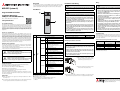
Overview
Installation and Wiring
The ME3CAN1-Q is used to connect a MELSEC System Q PLC system to CANopen쏐 and CAN Layer 2 networks. CAN (Controller Area Network) is a serial bus
system especially for networking devices as well as sensors and actuators.
MELSEC System Q
ME3CAN1-Q
�
RUN
b
CAN RUN
TX/RX
CAN ERR.
ERR.
Installation Manual for
CANopen쏐 Module ME3CAN1-Q
Safety Information
�
For qualified staff only
This manual is only intended for use by properly trained and qualified electrical technicians who are fully acquainted with automation technology safety
standards. All work with the hardware described, including system design,
installation, setup, maintenance, service and testing, may only be performed
by trained electrical technicians with approved qualifications who are fully
acquainted with the applicable automation technology safety standards and
regulations.
Proper use of equipment
b
WARNING:
Equipment and property damage warnings.
Failure to observe the precautions described here can result
in serious damage to the equipment or other property.
Description
RUN
ERR
쎲
Normally operating
쑗
Hardware error (watch dog timer error)
or power failure
쎲
An module error has occurred.
쑗
Normally operating
폷
CAN RUN
�
Status
LEDs
The following manuals contain further information about the module:
● Hardware manuals for the MELSEC System Q
● User's Manual for the CANopen쏐 module ME3CAN1-Q
● MELSEC-Q/L Programming Manual
Registration
● CiA쏐 and CANopen쏐 are registered Community Trademarks of CAN in
Automation e.V.
● The company name and the product name to be described in this manual
are the registered trademarks or trademarks of each company.
● When drilling screw holes or wiring, cutting chips or wire chips should
not enter ventilation slits. Such an accident may cause fire, failure or
malfunction.
● Make sure to affix the CAN bus connector with fixing screws.
Tightening torque should be within 0.20 to 0.28 Nm. Loose connections may cause malfunctions
● Do not disconnect the CAN bus cable connected to the ME3CAN1-Q by
pulling the cable section. Be sure to hold the connector connected to
the ME3CAN1-Q.
Pulling the cable while it is connected to the ME3CAN1-Q may lead to
malfunctioning or damage of the ME3CAN1-Q or cable.
● A protective film is attached onto the module top to prevent foreign
matters such as wire chips entering the module during wiring. Do not
remove the film during wiring. Remove it for heat dissipation before
system operation.
● Do not bundle or adjacently lay the communication cable connected
to the ME3CAN1-Q with the main circuit line, power line, or the load
line other than that for the PLC. Separate these by 100 mm as a guide.
Failure to observe this could lead to malfunctioning caused by noise,
surge, or induction.
● Before handling modules, touch a grounded metal object to discharge
the static electricity from the human body. Not doing so may cause
failure or malfunctions of the module.
● Place the communication cable in grounded metallic ducts or conduits
both inside and outside of the control panel whenever possible.
CAN ERR
Torque
Module fixing screw (M3, optional)
0.36 to 0.48 Nm
Relation between bus length and cable cross section
b
Bus length [m]
WARNING
Length-related
resistance (m⏲/m)
0 to 40
0.3 to 0.34
70
40 to 300
0.34 to 0.60
쏝60
● Do not open or modify a module. Doing so can cause a failure, malfunction, injury or fire.
300 to 600
0.50 to 0.60
쏝40
600 to 1000
0.75 to 0.80
쏝26
LSS Services in progress
쏆
CANopen쏐 mode: The device is in CANopen쏐 state Pre-operational.
왕
The device is in CANopen쏐 state Stopped.
● Always insert the module fixing latch of the module into the module
fixing hole of the base unit. Forcing the hook into the hole will damage
the module connector and module.
쑗
Layer 2 mode: The device is in Layer 2
offline mode.
● Do not touch the conductive parts of the module directly. Doing so can
cause a unit malfunction or failure.
쎲
Module is transmitting or receiving
CAN messages.
쑗
Module is not transmitting or receiving
CAN messages.
쎲
폷
폷
왖
LSS Services in progress
For details, refer to CiA쏐 303.
햲 After switching off the power supply,
insert the module fixing latch into the
module fixing hole of the base unit.
The CAN controller is Bus-OFF-state.
The CAN controller has too many
transmission errors.
쏆 General error
폷
Cable cross section (mm2)
● Do not drop the module or subject it to heavy impact.
왖
폷
Use twisted pair shielded cable (2 pairs) with a cross section of 0.3 to 0.82 mm2
and an impedance of 120 :. (The relation between the bus length and the
cross section of the wires to be used is given below.) The cables should conform to ISO 11898/1993.
Mounting a module to a base unit
폷
앳
�
CANopen쏐 mode: The device is in
CANopen state Operational.
Layer 2 mode: The device is in Layer 2
online mode.
Applicable Cable
Screw
쎲
Tx/Rx
Further Information
These manuals are available free of charge through the internet
(https://eu3a.mitsubishielectric.com).
If you have any questions concerning the installation, configuration or operation of the equipment described in this manual, please contact your relevant
sales office or department.
WARNING
Tighten the module screw within the following range.
No.
All safety and accident prevention regulations relevant to your specific application must be observed in the system design, installation, setup, maintenance, servicing and testing of these products.
In this manual special warnings that are important for the proper and safe use
of the products are clearly identified as follows:
m
● Always confirm the connector layout before connecting the CAN bus to
the ME3CAN1-Q.
ME3CAN1-Q
Relevant safety regulations
DANGER:
Personnel health and injury warnings.
Failure to observe the precautions described here can result
in serious health and injury hazards.
WARNING
● Make sure that foreign matter such as cutting chips and wire scraps
does not enter the ME3CAN1-Q. Failure to observe this could lead to
fires, faults or malfunctioning.
● Use the product in the environment within the general specifications
described in the Hardware Manual for the MELSEC System Q.
Never use the product in areas with dust, oily smoke, conductive dusts,
corrosive or flammable gas, vibrations or impacts, or expose it to high
temperature, condensation, or wind and rain.
CAN I/F
Art.no.: 279870 ENG, Version A, 09102014
The programmable controllers (PLC) of the MELSEC System Q are only
intended for the specific applications explicitly described in this manual or the
manuals listed below. Please take care to observe all the installation and operating parameters specified in the manual. All products are designed, manufactured, tested and documented in agreement with the safety regulations. Any
modification of the hardware or software or disregarding of the safety warnings given in this manual or printed on the product can cause injury to persons
or damage to equipment or other property. Only accessories and peripherals
specifically approved by MITSUBISHI ELECTRIC may be used. Any other use or
application of the products is deemed to be improper.
b
DANGER
Turn off all phases of the power supply for the PLC and other external
sources before starting the installation or wiring work.
Part Names
Programmable Controllers
m
Wiring
NMT guarding failure (NMT-Slave or
NMT-Master)
Heartbeat failure
왕
Warning limit reached
쑗
No error
햳 Push the module in the direction of the
arrow to load it into the base unit.
CANopen쏐 interface connector (D-sub 9-pin male connector)
쎲: LED ON
왖: Flickering (0.05 s ON, 0.05 s OFF)
쏆: Blinking (0.2 s ON, 0.2 s OFF)
앳: Two short flashes (0.2 s each) followed by a pause of 1 s
왕: One short flash (0.2 s) followed by a pause of 1 s
쑗: LED OFF
햴 Secure the module with an additional screw (M3 x 12) to the base unit if
large vibration is expected. This screw is not supplied with the module.
Mitsubishi Electric Europe B.V. /// FA - European Business Group ///
Germany /// Tel.: +49(0)2102-4860 /// Fax: +49(0)2102-4861120 ///
https://eu3a.mitsubishielectric.com
Pin Configuration
Specifications
Grounding of the twisted pair CAN bus cable
MELSEC System Q PLC
General Specifications
External dimensions
Threaded hole to fix CAN bus connector
5
.
.
.
.
1
9
.
.
.
6
Power supply
CPU
ME3CAN1-Q
ME3CAN1-Q
No. of occupied I/O points
32
(I/O assignment: 32 intelligent points)
Internal current consumption
(5 V DC)
0.34 A
Weight
0.12 kg
ME3CAN1-Q
RUN
ERR.
CAN bus cable
CAN RUN
TX/RX
CAN ERR.
CAN I/F
Performance Specifications
NOTE
ME3CAN1-Q
An inch screw thread (#4-40UNC) is used to fix the connector to the ME3CAN1-Q.
For noise prevention please attach at least 35mm of the shield from the twistedpair CAN bus cable to the grounding with a shielding connection clamp.
Pin
Item
98
Grounded mounting plate or
grounded DIN rail with a
grounding resistance of
100 : or less (Class D).
Signal
Description
1
—
Reserved
2
CAN_L
CAN_L bus line (dominant low)
3
CAN_GND
CAN ground
4
—
Reserved
5
CAN_SHLD
CAN shield
6
—
Reserved
7
CAN_H
CAN_H Bus line (dominant high)
8
—
Reserved
9
—
Reserved
Ground the communication cables as follows:
● The grounding resistance should be 100 : or less.
● The grounding point should be close to the ME3CAN1-Q. Keep the grounding wires as short as possible.
● Independent grounding should be performed for best results. When independent grounding is not performed, perform "shared grounding" of the
following figure.
ME3CAN1-Q
Other
equipment
Independent grounding
Best condition
ME3CAN1-Q
Other
equipment
Shared grounding
Good condition
ME3CAN1-Q
Other
equipment
Common grounding
Not allowed
Item
ME3CAN1-Q
Transmission type
CAN Bus network (RS485, CSMA/CR)
Applicable functions
앫 CANopen쏐 Node
앫 CAN Layer 2 Node
CANopen쏐 communication
services according to CiA쏐
standards
앫 CiA쏐-301 V4.2
앫 CiA쏐-302 V4.1
앫 CiA쏐-305 V2.2
CANopen쏐 device and application Interface and Device Profile CiA쏐-405
profiles according to CiA쏐
V2.0 for IEC 61131-3 Programmable
standards
Devices
Remote Transmit Request (RTR)
앫 Layer 2 mode: supported
앫 CANopen쏐 mode: not supported for
PDO
Node number
Selectable from 1 to 127
Communication method
Acyclic, cyclic or event-driven
The maximum bus length varies
depending on the transmission speed.
b
WARNING
Supported transmission speed /
maximum bus length
Leave the "reserved" pins unconnected.
CAN-Bus Wiring
�
�
CAN_GND
CAN_GND
Connection cable
CAN_GND
CAN_L
CAN_L
CAN_L
CAN_SHLD
CAN_SHLD
CAN_SHLD
CAN_H
CAN_H
CAN_H
CAN_V+
CAN_V+
CAN_V+
�
�
�
�
�
No.
Description
쐃
Terminating resistor (120 :, 0.5 W)
It is recommended to use a CAN bus connector with built-in bus
terminator.
쐇
4-core shielded twisted pair cable
쐋
Class-D Grounding (100 : or less)
For electromagnetic compatibility (EMC), it is recommended to
ground the cable shield at both ends.
쐏
Optional external supply for transmission hardware
b
앫 1 Mbps / 25 m
앫 800 kbps / 50 m
앫 500 kbps / 100 m
앫 250 kbps / 250 m
앫 125 kbps / 500 m
앫 100 kbps / 600 m
앫 50 kbps / 1,000 m
앫 20 kbps / 2,500 m
앫 10 kbps / 5,000 m
The cable should conform to ISO11898.
(Refer to section "wiring")
Connection to CANopen쏐 network via 9-pin D-sub connector
�
WARNING
For safety, always check the potential differences between the grounding
points. If potential differences are found, proper measures must be taken
to avoid damage.
Insulation method
앫 Photocouplers are used to insulate
the CAN input from the PLC.
앫 A DC/DC converter is used to insulate the power supply from the CAN
input.
Online module change
Not supported
27.4
All dimensions are in "mm".
90