1
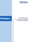
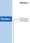
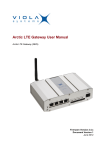
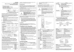
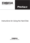
The FP-3710T Series unit needs the following software for operation. As FP user manual, provided by PDF media, describes its details, download the manual below and get the further information. Visit Pro-face website below and get both software and reference manual. (URL:http:// www.pro-face.com/otasuke/) • Software : Mouse Emulation Software • Manual : FP3000 Series User Manual FP-3710T Series Installation Guide Caution Be sure to read the “Warning/Caution Information” on the attached sheet before using the product. Package Contents Installation prerequisites for standards FP unit (1) Installation Guide (1) (this manual) Warning/Caution Information (1) Installation Gasket (1) (attached to the FP unit) Installation Fasteners (4/set, 2sets) USB Cable Clamp (1) For the detailed certification's information, refer to the Pro-face Home page. <Cautions> Be aware of the following items when building the FP into an enduse product: • For indoor use only. • This unit should be installed in the front face of a metal panel. • If this unit is installed so as to cool itself naturally, be sure to install it in a vertical panel. Also, be sure that the FP unit is mounted at least 100 mm away from any adjacent structures or equipment. If these requirements are not met, the heat generated by the FP unit’s internal components may cause the unit to fail to meet UL/c-UL standard. • For use on a flat surface of a Type 4X (Indoor Use Only) and/or Type 12 Enclosure. • Type 4X (Indoor Use Only) and/or 12 Enclosure, when the hatch for Front USB Port is secured by screw. Type 1 Enclosure, when the hatch for Front USB Port is open.(FP3710T42-U, FP3710-T42-24V-U only) • Receivable signals are only from isolated secondary source. Power Plug (1) (attached to the FP unit) AC type DC type This unit has been carefully packed, with special attention to quality. However, should you find anything damaged or missing, please contact your local FP distributor immediately. Required software/Reference manual 1 FP's Front Module • All interface ports (except for Front USB Connector (Type A) ) are not intended to be directly connected to a signal source greater than 30 volts and available current greater than 5mA. <Hazardous Locations Compliance and Handling Cautions> • WARNING: Suitable for use in Class I, Division 2, Groups A, B, C, and D Hazardous Locations or, Nonhazardous Locations only. • WARNING: Explosion hazard substitution of components may impair suitability for Class I, Division 2 Hazardous locations. • WARNING: Explosion hazard - do not disconnect equipment while the circuit is live or unless the area is known to be free of ignitable concentrations. USB Pin Description 1.Vcc 2.D3.D+ 4.GND Nonincendive Field Wiring Apparatus (See note 1 for detail) Shield. Gnd 1 2 3 4 Notes: (1) Nonincendive Circuit Parameters: Front USB I/F: Voc = 5.0 V, Isc = 1.25 A, Ca = 10 µF, La = 16 µH (2) Selected Associated Nonincendive Field Wiring Apparatus shall satisfy the following: <Control Drawing of USB I/F on FP's Front Module> The information below concerns the use of the USB I/F located on the FP unit's front modules used in Class I, Division 2 Groups A, B, C and D hazardous locations. (from Doc No. 35016429). Nonincendive Field Wiring Apparatus - Front module of FP unit Voc ≤ Vmax Isc ≤ Imax Ca ≥ Ci+C cable La ≥ Li+L cable (3) If the electrical parameters of the cable are unknown, the following values may be used: Capacitance = 60pF/ft, Inductive = 0.20 µH/ft (4) Nonincendive Field Wiring must be installed in accordance with article 501.10(B) of the National Electrical Code ANSI/NFPA 70. (5) Nonincendive Field Wiring Apparatus shall not contain or be connected to another source of power. CE Marking Notes For the detailed information, be downloaded and refer the Declaration of Conformity from Proface Home Page. • The FP3710-T42-U and FP3710T42 units are CE marked products that conform to EMC directives and Low Voltage directives. • The FP3710-T42-24V-U unit is CE marked products that conform to EMC directives. 2 Part Names Front View I J A,B Rear View (AC type) (DC type) C D E F G Bottom View (AC type) CDE (DC type) F G H A: TFT Color LCD Acts as a display monitor for your host. B: Touch Panel Allows you to switch screens or write data to the host. C: Power Connector (Socket) Provides the input and ground terminals for a power cable. D: Setting Switch By opening the cover, the Dip switches and slide switch are seen. Each switch can set a operation mode. E: Analog RGB Connector Connector for analog RGB interface F: DVI-D Interface Connector Connector for DVI-D interface G: Serial Connector Connector for serial (RS-232C) interface. Used for sending touch panel data to the host. H: USB Connector (Type B) Connector for USB interface. Used for sending touch panel data to the host or used as an upstream port for USB-HUB. I: Front LED Used to indicate the condition of the power supply, a backlight burnout or image signal input. J: Front USB Connector (Type A)(FP3710T42-U and FP3710-T42-24V-U) A downstream port for embedded USBHUB in conformity with USB2.0/1.1 standard, which is used for connecting USB devices. Connect the upstream port of the USB-HUB (H:USB connector) to the Host PC for Front USB connector use. 3 Dimensions Top View Unit: mm [in] 383 [15.08] 294 [11.57] 282 [11.10] 60 [2.36] 5 [0.20] 395 [15.55] Side View Front View Dip Switches and Slide Switch The Dip Switches and Slide Switch are located in the bottom of the FP unit. Only the settings when the power supply is turned on is effective to the Dip Switches and the Slide Switch. Turn off the power before changing the settings of this unit. Bottom View Dip Switches(SW1) Slide Switch(SW2) SW1 Switch Setting SW1-1 Reserved (Always OFF) SW1-2 Display/Hide the OSD ON SW1-3 Reserved (Always OFF) SW1-4 Reserved (Always OFF) 1 2 3 4 5 67 8 SW1-5 Reserved (Always OFF) SW1-6 Reserved (Always OFF) SW1-7 Reserved (Always OFF) SW1-8 Reserved (Always OFF) • SW1-2 Dip Switch SW1-2 is used to display or hide the OSD. To hide the OSD, set the switch to ON. To display the OSD, set the switch to OFF. The default setting is OFF. (OSD is displayed.) SW2 USB 232 Switch Setting Slide Switch is used to switch the data input/output (command control) method on the touch panel between USB and RS-232C (Serial). The default setting is RS232C. 4 Interfaces Analog RGB Interface Input signal type Input signal characteristic Setting by OSD (On Screen Display) Analog RGB Image signal : analog RGB Synchronous signal :TTL level, negative true or positive true Scanning type : non-interlace •BRIGHTNESS •CONTRAST •H-POSITION •V-POSITION •H-size •PHASE •DIMMER(BACKLIGHT) •SHARPNESS •ALL RESET (DEFAULT) The number of dots (pixels) displayed are as follows: H Sync. (kHz) Size 640×400 640×400 640×480 640×480 640×480 24.827 31.469 31.469 35.000 37.500 V Sync. (Hz) 56.000 70.000 59.992 66.667 75.000 720×400*1 31.469 70.000 800×600 800×600 1024×768 1024×768 1024×768 37.879 46.875 48.363 56.476 60.023 60.317 75.000 60.004 70.069 75.029 Screen Resolution Dot Clock Expansion (MHz) (H: Horizontal)(V: Vertical) 21.053 ×1.6 (H) ×1.92 (V) 25.175 25.175 30.240 ×1.6 31.500 ×1.42 (H) 28.320 ×1.92 (V) 40.000 1.28 49.500 65.000 75.000 1.0 78.750 Display Resolution 1024×768 *1 When you use this resolution, set “ON” for “720 × 400 Mode” in the OSD (On Screen Display) “System Settings”. Pin Assignments and Signal Names for Analog RGB Pin Pin Pin Signal Name Signal Name Signal Name Pin Location No No No 1 Analog R 6 Return R 11 2 Analog G 7 Return G 12 DDC DATA 3 Analog B 8 Return B 13 H. SYNC 4 Reserved 9 Reserved 14 V. SYNC 5 Digital grounding 10 Digital grounding 15 Reserved DDC CLOCK Connector ..................... Mini Dsub 15 pin male Connector set screw ..... Inch type (4-40UNC) Cable............................. RGB cable manufactured by Pro-face. FP-CV02-45 <4.5m> 5 15 11 5 1 • If a cable other than the specified RGB cable is used, product performance cannot be guaranteed due to the possibility of noise interfering with the FP unit’s operation. DVI-D Interface Input signal type DVI-D •CONTRAST •DIMMER(BACKLIGHT) •ALL RESET (DEFAULT) Setting by OSD (On Screen Display) •BRIGHTNESS •SHARPNESS Display Area Size 640×400 640×400 640×480 640×480 640×480 H Sync. (kHz) 24.827 31.469 31.469 35.000 37.500 V Sync. (Hz) 56.000 70.000 59.992 66.667 75.000 720×400*1 31.469 70.000 800×600 800×600 1024×768 1024×768 1024×768 37.879 46.875 48.363 56.476 60.023 60.317 75.000 60.004 70.069 75.029 *1 Dot Clock Screen Resolution Expansion Display (MHz) (H: Horizontal)(V: Vertical) Resolution 21.053 ×1.6 (H) ×1.92 (V) 25.175 25.175 30.240 ×1.6 31.500 ×1.42 (H) 1024×768 28.320 ×1.92 (V) 40.000 ×1.28 49.500 65.000 75.000 ×1.0 78.750 When you use this resolution, set “ON” for “720 × 400 Mode” in the OSD (On Screen Display) “System Settings”. Pin Assignments and Signal Names for DVI-D Pin Signal Name Pin Signal Name Pin 1 2 NC 22 7 8 DDC Data NC 15 16 GND Hot Plug Detect 23 24 Connector ..................... DVI-D 24-pin male Connector set screw ..... Inch type (4-40UNC) Cable............................. DVI-D cable manufactured by Pro-face. (FP-DV01-50 <5 m>, FP-DV01-100 <10 m>) 6 8 14 16 DDC Clock 19 Pin Location 24 20 21 Signal Name TMDS DATA0TMDS DATA0+ TMDS DATA0 SHIELD 17 NC NC TMDS CLOCK 24 SHIELD TMDS CLOCK+ TMDS CLOCK- 1 12 13 11 17 18 9 6 3 TMDS DATA1TMDS DATA1+ TMDS DATA1 SHIELD NC NC 17 9 10 4 5 TMDS DATA2TMDS DATA2+ TMDS DATA2 SHIELD NC NC 1 8 • If a cable other than the specified DVI-D cable is used, product performance cannot be guaranteed due to the possibility of noise interfering with the FP unit’s operation. • Only when the FP-3710T series is connected with PS-2000B or PL-3000B (Revision B or more), FP-DV01-100 can be used. • Please turn on PS-2000B's internal dipswitch 4 when you use FP-DV01-100 with PS-2000B. (The resolution that can be displayed is 1024 x 768 only (XGA). ) Please turn off dipswitch 4 when you use FP-DV01-50. • Please set PL-3000B’s internal dipswitch 5 to z sign side when you use FP-DV01-100 with PL-3000B. We will recommend the resolution of PL-3000B to change to the maximum display resolution of FP additionally. Please set it on the opposite side of z sign when you use FPDV01-50. Serial Interface Baud rate : 9600 bps Data length : 8 bits Parity : None Stop bit :1 Flow Control: None RS-232C Serial Interface Pin Assignments and Signal Names for Serial Interface Pin No. Signal Name Condition 1 2 3 4 5 6 7 8 9 CD RD SD DTR GND DSR RS CS NC Carrier Detect*1 Receive Data (FP->Host) Send Data (FP<-Host) Data Terminal Ready*1 Ground Data Set Ready*1 Request to Send (FP<-Host) Clear to Send (FP->Host) (Used internally) Pin Location 6 9 1 5 *1 The CD, DTR, and DSR are connected together inside of the FP. Connector ..................... Dsub 9 pin female Connector set screw ..... Inch type (4-40UNC) Cable............................. SIO cable for FP manufactured by Pro-face. (FP61V-IS00-O) Concerning Signal Names Signal names used for the serial interface on FP units are designed to match the pin order used on most PC serial interfaces, so that a straight cable can be used to connect the two. Therefore, connect each pin’s signal to the same signal name on the PC side. For example, pin #2 ‘RD’ should be connected to the ‘RD’ input terminal on the PC’s connector. Refer to the FP3000 Series User Manual’s section “Cable Diagrams” for each signal’s direction. 7 USB Interface (Type-B connector : Up-Stream Port) Pin Assignments and Signal Names for USB Interface Pin No. Signal Name Condition Pin Location 1 2 3 USB1-5V USBD1(-) USBD1(+) +5VIN USB data(-) USB data(+) 2 1 4 GND Ground 3 4 Cable............................. USB cable manufactured by Pro-face. (FP-US00) • If a cable other than the specified USB cable is used, product performance cannot be guaranteed due to the possibility of noise interfering with the FP unit’s operation. Installation (1) According to the Panel Cut size, make installation holes on the panel. Also, determine the panel thickness according to the panel thickness range with due consideration of panel strength. Panel r ≤ 3[0.12] thickness X Y Unit: mm [in] FP FP X Y +1.0 383.5 -0 FP-3710T Series +0.04 [15.10 -0 Panel thickness +1.0 282.5 -0 +0.04 ] [11.12 -0 ] 1.6 [0.06] to 10.0 [0.39] (2) Check that FP has installation fasteners. Insert the FP from the front. • Installation gasket must be used even though it is not necessary for its environment. For installation, refer to the FP3000 Series User Manual. • Check that the installation panel or cabinet's surface is flat, in good condition and has no jagged edges. Also, if desired, metal reinforcing strips can be attached to the inside of the panel, near the Panel Cut, to increase the panel's strength. 8 (3) The following figures show the eight (8) fastener insertion slot locations. Insert each fastener's hook into the slot and tighten it with a screwdriver. Top Installation fastener Panel Insertion Slots FP Hook Bottom Left side Right side • Tightening the screws with too much force can damage the FP unit’s case. • The necessary torque is 0.5 N•m (4.4 lb-in). Wiring • To avoid an electric shock, when connecting the FP’s power cord terminals to the power terminal block, confirm that the FP’s power supply is completely turned OFF, via a breaker, or similar unit. • To avoid the dangers of fire, electric hazards and equipment damage, be sure to use only the specified voltage when operating the FP. • Since there is no power switch on the FP unit, be sure to attach a breaker-type switch to its power cord. Electrical Specification Power Supply Item Rated Voltage Allowable Voltage Rated Frequency Allowable Frequency Range Allowable Voltage Drop Current Consumption In-Rush Current Voltage Endurance Insulation Resistance Specification DC TYPE DC24V DC19.2 to 28.8V 5ms or less AC TYPE AC100 to 240V AC85 to 264V 50 / 60HZ 40 - 72Hz 1 cycle (Max.) (Voltage drop interval must be 1s or more.) AC100V 1.1A or less (TYP0.75A) AC240V 0.7A or less (TYP0.44A) 30A or less 60A or less AC1000V 20mA for 1 minute AC1500V 20mA for 1 minute (between charging and FG (between charging and FG terminals) terminals) DC500V 10MΩ or more DC500V 10MΩ or more (between charging and FG (between charging and FG terminals) terminals) 40W or less 9 Environmental Specification Item Surrounding Air Temperature Storage Temperature Ambient Humidity Storage Humidity 1. Specification 0 to 50ºC (The panel should not incline more than 30º) -20 to +60ºC 10 to 90%RH (No condensation, Wet bulb temperature: 39ºC max.) Air Purity (Dust) 0.1mg/m3 (Max.) (No electrically conductive dust is allowed) Pollution Degree For use in Pollution Degree 2 environment Wiring the DC type power supply cable • Accompanying DC type power supply connector is CA7-DCCNL01 from Pro-face or GFKC2,5/3STF-7,62 is manufactured by Phoenix Contact. Power Cord Specifications Use copper conductors only. Power Cord Diameter Conductor Type Conductor Length *1 0.75 to 2.5mm2 (18 to 12 AWG) Connecting the Power Cord (1) Confirm that the power is not supplied to the FP unit. (2) Push the Opening button with a small and flat screw driver to open the desired pin hole. (3) Insert each pin terminal into its each hole. Release the Opening button to clamp the pin in place. Simple or Stranded Wire*1 10mm [0.39in] If the Conductor’s end (individual) wires are not twisted correctly, the end wires may either short against each other, or against an electrode. DC power supply cord Opening Button +(24V) -(0V) Wiring FG When connecting the power cord, use the following items when performing wiring. (Items are made by Phoenix Contact.) (4) After inserting all three pins, insert the Power Plug into the Power Connector at FP. Fix the plug with two (2) minus screws. Recommended SZS 0.6x3.5 (1205053) Driver AI 0.75-10GY (3201288) Recommended AI 1-10RD (3200182) Pin Terminals AI 1.5-10BK (3200195) AI 2.5-12BU (3200962) • The torque required to tighten these screws is 0.5 to 0.6 N•m (4.4 to 5.3 lb-in). • To prevent the possibility of a terminal short, use a pin terminal that has an insulating sleeve. Recommended CRIMPFOX ZA3 Pin Terminal (1201882) Crimp Tool 10 2. Wiring the AC type power supply cable • Accompanying AC type power supply connector is CA7-ACCNL-01 from Pro-face or FKC2,5/3-STF5,08 is manufactured by Phoenix Contact. • When the FG terminal is connected, be sure the wire is grounded. Not grounding the FP unit will result in excessive noise. Use your country's applicable standard for grounding. Connecting the Power Cord (1) Confirm that the power is not supplied to the FP unit. (2) Push the Opening button with a small and flat screw driver to open the desired pin hole. (3) Insert each pin terminal into its each hole. Release the Opening button to clamp the pin in place. Power Cord Specifications Use copper conductors only. Power Cord Diameter Conductor Type Conductor Length 0.75 to 2.5mm2 (18 to 12 AWG) Simple or Stranded Wire*1 10mm [0.39in] AC power supply cord Opening Button L N FG *1 (4) After inserting all three pins, insert the Power Plug into the Power Connector at FP. Fix the plug with two (2) minus screws. If the Conductor’s end (individual) wires are not twisted correctly, the end wires may either short against each other, or against an electrode. Wiring When connecting the power cord, use the following items when performing wiring. (Items are made by Phoenix Contact.) Recommended SZS 0.6x3.5 (1205053) Driver AI 0.75-10GY (3201288) Recommended AI 1-10RD (3200182) Pin Terminals AI 1.5-10BK (3200195) AI 2.5-12BU (3200962) Recommended CRIMPFOX ZA3 Pin Terminal (1201882) Crimp Tool • Confirm that all wires are connected correctly. • The torque required to tighten these screws is 0.5 to 0.6 N•m (4.4 to 5.3 lb-in). • To prevent the possibility of a terminal short, use a pin terminal that has an insulating sleeve.. Using the USB Cable Clamp USB Cable Clamp Attachment Procedure Installation to USB cable (1) Connect the USB cable to the connector. 11 • Must be used with a Class2 Power Supply.(FP3710-T42-24VU) (2) Insert the cable clamp into the cable clamp holder as shown in the following figure, and tighten the clamp until the cable is secured in place. USB Cable Stopper Grounding Caution USB cable clamp When attaching a wire to the FP unit’s rear face FG terminal, (on the AC Connector), be sure to create an exclusive ground. (Use a grounding resistance of 100Ω, a wire of 2mm2 or thicker, or your country’s applicable standard.) USB cable clamp holder USB Cable Clamp Removal Feature (1) Push in the cable clamp’s stopper until the cable clamp is unlocked, then remove the clamp. Input/Output Signal Line Cautions (2) Disconnect the USB cable. • All FP Input and Output signal lines must be separated from all operating circuit (power) cables. • If this is not possible, use a shielded cable and ground the shield. Power Supply Cautions Please pay special attention to the following instructions when connecting the power cord terminals to the FP unit. • If the power supply voltage exceeds the FP unit’s specified range, connect a voltage transformer. • Between the line and the ground, be sure to use a low noise power supply. If there is still an excessive amount of noise, connect a noise reducing transformer. • Input and Output signal lines must be separated from the power control cables for operational circuits. • The FP unit’s power supply cord should not be bundled with or kept close to main circuit lines (high voltage, high current), or input/ output signal lines. • Connect a surge absorber to handle power surges. • To reduce noise, make the power cord as short as possible. • The temperature rating of field installed conductors: 75 ºC only. Calibration of OSD Display Position OSD Functions You can operate the FP screen menus via the touch panel, and even if FP is operating, adjust screen image display to a minute level. The feature is called OSD (On Screen Display). The items that can be set with OSD and the functions are shown. Example of OSD screen "Ver.*.**" indicates the version of the OSD. 12 Item Function Color Settings Adjusts the contrast and the brightness. Screen Settings Adjusts the display position of the screen. Custom Display Adjusts Sharpness and the backlight brightness. System Settings Changes settings such as activating the click sound. All Reset Resets the current OSD value to the default value. Input Source Switches Analog RGB and DVI-D. Auto Adjust Auto Gain Automatically adjusts the display position of the screen. (Analog RGB only) Automatically adjusts the contrast and the brightness. (Analog RGB only) ESC Cancels the setting and returns to the upper level. SET Applies the setting and returns to the upper level. Arrow KEY Changes the selection. SELECT Selects icons or items. SAVE Saves the current value and quits the OSD. EXIT Quits the OSD. Starting the OSD To start the OSD and enter OSD mode, press the three corners of the touch panel in turn (upper left, upper right, and lower right) within 5 seconds. In OSD mode, the setting screen is displayed in the center of the screen. In this mode, the touch panel cannot be used to export data to external devices unless the settings for the OSD are completed. • OSD is not displayed when a SW 1-2 is ON. Using the OSD Icons on the screen are used to operate the OSD. After the OSD start-up, the top menu displays. Touching the icon you want to adjust displays its submenu or setting change screen. In the setting change screen, icons are used to change the setting. To apply the setting, press the button. Press the button to save the defined settings. Quitting the OSD To quit the OSD, press the or OSD as it is for at least 30 seconds. button in the top menu or leave the 13 • In the OSD, pressing the button applies the set value and enables the setting. The set value won’t be canceled unless the power is turned OFF or the value is reset. If the power is turned OFF without saving the set value, that data will disappear. The last saved data will be read into the system when the FP starts. To enable the changed value, be sure to press the button. • All the setting values, even though in process of the OSD settings, will be retained in condition of letting the OSD leave more than 30 seconds or by pressing the button. The OSD will keep those values and make them effective until power-off or a Reset command input. Top Main Color Settings Selection of the change item Adjustment button Contrast R.Contrast G.Contrast B.Contrast Brightness Applies the setting and then returns to the top menu. Cancels the setting and then returns to the top menu. Screen Settings Selection of the change item Adjustment button (Analog RGB only) (Analog RGB only) (Analog RGB only) (Analog RGB only) Clock for output to TFT-color display can be finely adjusted according to 9 levels. (Default: 50) Please use to the default value normally. Applies the setting and then returns to the top menu. H.Position V.Position H.size Phase Display Clock Cancels the setting and then returns to the top menu. Custom Display Selection of the change item Adjustment button Sharpness Dimmer Auto Adjust Enable OSD Transparent Applies the setting and then returns to the top menu. Cancels the setting and then returns to the top menu. 14 System Settings Selection of the change item Adjustment button Enables/disables the click sound. With this parameter, the sound level can also be adjusted. (Default value: OFF <Click sound disabled>) 720x400 Mode When an input data resolution of 720 x 400 is used in the VGA text mode, set this parameter to ON. For other resolutions, set this parameter to OFF. (Default: ON) Auto off Disp Enables/disables the screen display Auto OFF function and sets the time when the Auto OFF function is enabled. (Default: OFF <Auto OFF function disabled>) The Auto OFF function automatically turns off the display to prevent the screen from burning out when the touch panel is not used for some period of time. With this parameter, you can set the time interval to turn off the screen display (how much time passes before the screen display is turned off) when the touch panel is not used. If the touch panel is not touched over the set time, the backlight will automatically turns off. Select the time period from 1 min, 3 min, 5 min, 10 min, and OFF (Auto OFF function disabled). Enables/disables the Backlight burnout detect BL Alarm function. (Default: ON) When a burned-out backlight is detected, the status LED flashes alternately green and red, or a steady orange. Touch-operation will be disabled when the backlight burns out, which prevents the FP from sending input signals to the PLC. • Normally, the FP unit detects a backlight burnout by monitoring the backlight’s current flow, however, the FP may fail to detect this condition, depending on the type of backlight problem. Detect 2-Point Touch Enables to halt the data output procedure when two points of the touch panel are pressed. (Default: OFF <Disable>) • When doing the touch operation on a screen like the desktop of Windows®, disable this function. • Depending on the conditions, it may not be able to be detected that the two points were pressed. Power on Buzzer Enables/disables the buzzer sound in turning on the power. (Default: ON <Buzzer sounds enabled>) USB Touch Panel ID Set the touch panel ID number using the number 0 to 3, when connecting to USB. (Default: 0) Applies the setting and then returns to the top menu. Click Tone Cancels the setting and then returns to the top menu. 15 All Reset Resets all the settings and then returns to the top menu. Cancels the setting and then returns to the top menu. Input Source Switches Analog RGB and DVI-D, and quits the OSD. Cancels the setting and then returns to the top menu. Auto Adjust (Analog RGB only) Applies the setting and then returns to the top menu. Cancels the setting and then returns to the top menu. • Be sure to perform the auto adjust while things except that black are shown on sides of the display. Auto Gain (Analog RGB only) Applies the setting and then returns to the top menu. Cancels the setting and then returns to the top menu. • Be sure to perform the auto gain control when the screen has both 100% black and 100% white areas displayed. Icon decision Icon selection Saves the setting and quits the OSD. Saves all the adjusted settings in the EEPROM. End of OSD Note Regardless of the above clause, Digital Electronics Corporation shall not be held responsible for any damages or third-party claims for damages or losses resulting from the use of this product. Digital Electronics Corporation 8-2-52 Nanko Higashi, Suminoeku, Osaka 559-0031, Japan URL:http://www.pro-face.com/ The information in this document is subject to change without notice. PFX122672K .FP3710-MT23E-BTH 2012.3 SS/B ©2011 Digital Electronics Corporation 16 Addendum Anexo PHA99478 08/2018 Annexe California Proposition 65 Warning—Lead and Lead Compounds Advertencia de la Proposición 65 de California—Plomo y compuestos de plomo Avertissement concernant la Proposition 65 de Californie— Plomb et composés de plomb WARNING: This product can expose you to chemicals including lead and lead compounds, which are known to the State of California to cause cancer and birth defects or other reproductive harm. For more information go to: www.P65Warnings.ca.gov. All trademarks are the property of Schneider Electric SE, its subsidiaries, and affiliated companies. Schneider Electric USA, Inc. 800 Federal Street Andover, MA 01810 USA 888-778-2733 www.schneider-electric.us ADVERTENCIA: Este producto puede exponerle a químicos incluyendo plomo y compuestos de plomo, que es (son) conocido(s) por el Estado de California como causante(s) de cáncer y defectos de nacimiento u otros daños reproductivos. Para mayor información, visite : www.P65Warnings.ca.gov. Todas las marcas comerciales son propiedad de Schneider Electric SE, sus filiales y compañías afiliadas. Importado en México por: AVERTISSEMENT: Ce produit peut vous exposer à des agents chimiques, y compris plomb et composés de plomb, identifiés par l'État de Californie comme pouvant causer le cancer et des malformations congénitales ou autres troubles de l’appareil reproducteur. Pour de plus amples informations, prière de consulter: www.P65Warnings.ca.gov. Toutes les marques commerciales sont la propriété de Schneider Electric SE, ses filiales et compagnies affiliées. Schneider Electric México, S.A. de C.V. Schneider Electric Canada, Inc. Av. Ejercito Nacional No. 904 Col. Palmas, Polanco 11560 México, D.F. 55-5804-5000 www.schneider-electric.com.mx 5985 McLaughlin Road Mississauga, ON L5R 1B8 Canada 800-565-6699 www.schneider-electric.ca © 2018 Schneider Electric All Rights Reserved / Reservados todos los derechos / Tous droits réservés