1
ROSE
Serial Number
USER INSTRUCTIONS
DYNA-LOCK® SELF-RETRACTING
LANYARD
! WARNING
National standards and Federal, state, and provincial laws require the user
to be trained before using this product. Use this manual as part of a user
safety training program that is appropriate for the user’s occupation. These
instructions must be provided to users before use of the product and
retained for ready reference by the user. The user must read, understand (or
have explained), and heed all instructions, markings, and warnings
supplied with this product and with those products intended for use in
association with it. FAILURE TO DO SO MAY RESULT IN SERIOUS INJURY
OR DEATH.
1.0
SPECIFICATIONS
•
The Dyna-Lock Self-Retracting Lanyard meets ANSI Z359.1-1992, ANSI A10.14-1991, CSAZ259.2-M1979,
and OSHA 29 CFR Part 1910.66 Appendix C-1989. These instructions and the labels on the product fulfill the
requirements of those standards.
•
Maximum Free Fall Distance: 6 ft. (1.8m) per OSHA and ANSI Z359.1. ANSI A10.14 and the Canadian
Occupational Health and Safety Act of 1978 limits free fall distance to 5 ft. (1.5m). The user must comply with
applicable standards and regulations.
•
•
•
Capacity: 75 to 310 lbs (34 to 141 kg) including weight of the user plus tools, clothing and other user-borne objects.
Weight: 6.5 lbs (3 kg).
Line (Lanyard):
Size: 1 in (25 mm) wide x 0.085 in (1.2 mm) thick
Material: Nylon Webbing
Length: 20 ft. (6m)
Min. Breaking Strength: 4,500 lbf (20 kN)
100% proof tested to 3,600 lbf. (16kN)
•
Snaphook:
Type: Self-closing and self-locking; two actions to open; swivel type
Material: Forged steel, zinc plated
Min. Breaking Strength: 5,000 lbf (22 kN)
100% proof tested to 3,600 lbf (16 kN)
Copyright © 1994-2000 Rose Manufacturing Company
PN 622617, Rev. C
USER INSTRUCTIONS - DYNA-LOCK ®
Page 2 of 28 pages
•
ANSI Z359.1, Section 4.3.7.1 Dynamic Performance Test Results
Maximum Arrest Force:
900 lbf (4 kN) measured
1,800 lbf (8 kN) allowable
Maximum Arrest Distance:
40 in (1m) measured
54 in (1.4m) allowable
2.0 TRAINING
It is the responsibility of the purchaser of the Dyna-Lock to assure that product users are made familiar with these User
Instructions and trained by a competent person in: (1) workplace hazard awareness and hazard identification,
evaluation, and control; (2) how to properly select, inspect, use, store, and maintain the Dyna-Lock; (3) how to
determine and acceptably limit free fall distance, and maximum arresting force; (4) how to select and make connections
to anchorages and anchorage connectors; (5) proper attachment locations on the user’s harness and other
components of personal fall arrest systems and proper attachment methods including compatibility of connections to
reduce the probability of accidental disengagement (rollout); (6) how to evacuate from a hazardous space; (7) what
to do after a fall to protect the user from injury, including emergency rescue planning and execution; and (8) the
consequences of improper use of the Dyna-Lock and associated equipment and of failure to follow instructions and
training. If the Dyna-Lock is to be used for confined space applications, the user must also be trained in accordance
with the requirements of OSHA regulation 29 CFR 1910.146 and ANSI Z117.1. Training must be conducted without
undue exposure of the trainee to hazards. The effectiveness of training should be periodically assessed (at least
annually) and the need for more training or retraining determined. Rose offers training programs. Contact Rose for
training information.
3.0 HAZARDS IDENTIFICATION, EVALUATION AND CONTROL
!
CAUTION
Do not use the Dyna-Lock unless a qualified person has inspected the
workplacand determined that identified hazards can neither be eliminated
nor exposures to them prevented.
Prior to selecting a self-retracting lanyard or other personal protective equipment, the user must make a workplace
assessment of hazards and conditions where the equipment is required. Such assessment must, at a minimum, identify
the presence of:
• Hot objects
• Sparks
• Flames
• Heat-producing
operations
•
•
•
•
Chemicals
Electric hazards
Sharp objects
Environmental
• Abrasive surfaces • Climatic factors
• Moving equipment • Weather factors
• Moving materials • Unstable/uneven surfaces
• Unguarded openings • Confined space hazards
contaminants
• Slippery surfaces
Foreseeable changes in any of these conditions, taken individually or collectively, must be identified, evaluated, and
controlled. The materials and construction of the Dyna-Lock and associated equipment must be considered in the
selection process such that these workplace conditions are suitably addressed and responded to. The equipment must
match the work situation and workplace environmental factors.
The workplace assessment must identify all paths of intended user movement and all hazards along such paths. The
user must identify the required range of mobility in each hazard zone and note the location and distance to all
obstructions in potential fall paths. Lateral obstructions which could be contacted in a pendular fall arrest must be noted.
P/N 622617, Rev. C
Copyright © 1994-2000, Rose Manufacturing Company
USER
INSTRUCTIONS
-
DYNA-LOCK ®
Page 3 of 28 pages
The self-retracting lanyard connecting the user’s harness to an anchorage must be selected so as to satisfactorily limit
total fall distance and allow for dynamic elongation and activation distance of the assembly. If the Dyna-Lock is to be
used for confined space entry operations, the workplace assessment must comply with the requirements of OSHA
regulations 29 CFR 1910.146 and ANSI Z117.1.
4.0 DESCRIPTION OF DYNA-LOCK SELF-RETRACTING LANYARD
The Dyna-Lock is a device which has a metal housing and a line (lanyard) connected to a drum inside the housing. An
internal spring causes the drum to windup the line when there is no load on the line. An internal pawl/sperrad locking
mechanism is designed to lock the drum when the line is pulled out quickly, which will occur in case of an accidental fall
by the user.
The housing has a steel handle which is used to connect the device to an anchorage. The free end of the line has a
swivel-type steel snaphook which is used to connect to the back D-ring of the user’s harness.
The snaphook is operable with one hand and automatically closes and locks when released. It has an integral swivel
which allows the snaphook to rotate without twisting the line. The snaphook also has a load indicator which is activated
when the Dyna-Lock is subjected to fall arrest forces. When it is activated, a yellow metal tab is exposed to indicate that
a high impact force has been applied to the Dyna-Lock. The Dyna-Lock must be returned to Rose, or a person
authorized in writing by Rose, after being subjected to fall arrest forces.
The line is the primary energy absorbing element of the Dyna-Lock. When a fall arrest force is applied to the line, the
energy is dissipated by the tightening of the line wrapped around the drum combined with the stretch of the line.
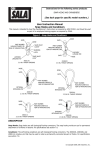
I.D./Service
Label
Handle
Housing
Caution Labels
(each side)
Inspection
Label
Specification
Label
Line
Stitching
Load Indicator
Tab
Load Indicator
Label
Swivel Snaphook
DYNA-LOCK SELF-RETRACTING LANYARD
Copyright © 1994-2000 Rose Manufacturing Company
PN 622617, Rev. C
USER INSTRUCTIONS - DYNA-LOCK ®
Page 4 of 28 pages
Release lock and lever to allow
gate to close and lock.
ALWAYS CHECK
3/4" throat
opening
Hook Body
Lever
1 Press to
unlock.
2 Pivot to
open.
Lanyard
SWIVEL SNAPHOOK
5.0
DYNA-LOCK SELECTION AND APPLICATIONS
5.1
PURPOSE OF THE DYNA-LOCK
The Dyna-Lock Self-Retracting Lanyard is designed for use by one person working at an elevated work level, which
does not have existing fall prevention provisions. The Dyna-Lock links the user to an overhead anchorage. It has a
20 foot (6-meter) long self-retracting, nylon web lanyard which allows the user to move around in his work area. It will
automatically stop his descent in a short distance after onset of an accidental fall.
The Dyna-Lock dissipates the energy built up during the fall as it decelerates the user and then suspends the user until
rescued.
The device is designed to be mounted with its snaphook connected to the back D-ring of the user's harness. Never
attempt to use the device for protection against falls of equipment or materials.
Anchorage
Anchorage
connectors
Line (Lanyard)
Dyna-Lock
Harness
FALL ARREST SYSTEM USING DYNA-LOCK
5.2
SELECTION
Rose offers several Dyna-Lock self-retracting lanyards in addition to the 20 foot (6 meter) nylon web type device. These
include devices with wire rope lines of varying lengths. The wire rope line is more suitable to applications where
abrasive surfaces or sharp edges may be encountered. The line lengths available are approximately 30, 50, 70, and
95 feet (10, 16, 22, and 30 meters). Consult Rose for more information on these products.
Use of the Dyna-Lock must comply with these User Instructions and, further, is subject to approval under the user’s safety
rules and regulations and by the user’s safety director, supervisor, or a qualified safety engineer. Be certain the
selection of the Dyna-Lock is suited for the intended use and work environment. If there is any conflict between these
P/N 622617, Rev. C
Copyright © 1994-2000, Rose Manufacturing Company
USER
INSTRUCTIONS
-
DYNA-LOCK ®
Page 5 of 28 pages
User Instructions and other directives or procedures of the user’s organization, do not use the Dyna-Lock lanyard until
such conflicts are resolved. Consult all local, state, and federal Occupational Health and Safety Administration (OSHA)
requirements for personal safety equipment. Also refer to the latest revision of ANSI Z359.1 and ANSI A10.14 standards
for more information on full body harnesses and associated system components. In Canada, refer to provincial and
federal regulations and to CSA Z259.2.
5.3
USE: Before proceeding with any work which requires the use of a fall arrest system, the user must have a rescue plan.
If a user falls and is suspended from the fall arrest system, it may be necessary to provide assistance in returning the
user to a safe place. This must be done as quickly as possible to avoid injury. All rescue equipment and personnel
required to implement the plan must be readily available, should the need arise.
5.3.1
CONNECTING THE DYNA-LOCK
To proceed with the use of the Dyna-Lock, connect the handle of the Dyna-Lock securely to the anchorage connector.
The user then pulls the snaphook on the end of the lanyard out of the Dyna-Lock and connects it securely to the back
D-ring on the user’s full body harness. Be certain the snaphook gate is completely closed and locked. Always connect
the Dyna-Lock snaphook to the body harness at the D-ring located in the center of the back. When force is applied to
the harness D-ring located in the center of the back, the human body can tolerate greater impact forces during fall arrest
and can endure suspension longer after fall arrest than when the force is applied to the body from the side(s) or front.
5.3.2
MOVING AROUND IN THE WORK AREA
Move around carefully to prevent loss of balance from line tension or locking. The Dyna-Lock maintains normal line
tension of approximately 3 to 7 lbs (13 to 31 N) when line is being steadily extracted and retracted. When line is being
extracted, the brake will lock at a rate of about 4.5 ft./sec. (1.4 m/sec). The user should practice using the device on a
flat surface where no fall hazard exists. This will familiarize the user with the tension and locking actions and make him
aware of the forces applied to his body by the line during movement. When moving toward the anchorage, move at a
rate which does not permit line slack to build up. When moving away from the anchorage, move at a rate that is less
than the device locking speed. Avoid quick or sudden movements in any direction.
Do not permit slack line, and do not lengthen the line by connecting to another line. Slack line will cause increased free
fall distance, increased deceleration distance, and increased decelerative forces on the body. Slack line can also
present a tripping hazard to the user and can allow the line to become snagged or tangled on objects in the work area,
which, in turn, can cause line damage or eliminate the shock absorbing action of the device. Lengthening the line by
attachment of more line will cause slack line when the Dyna-Lock line is fully retracted since no automatic line tension
will then be transmitted to the added line.
Never work at a level where the point of attachment of the body harness is above the anchorage connector because
this will increase the free fall distance and the deceleration distance and will cause higher forces on the body in the
event of an accidental fall.
5.4
USA
GE
USAGE
LIMIT
ATIONS
LIMITA
The following application limitations must be considered and planned for before using the Dyna-Lock.
5.4.1
PHYSICAL LIMITATIONS
The Dyna-Lock is designed for use by one person with a combined total weight between 75 and 310 lbs (34 - 141 kg),
including clothing, tools, and other user-borne objects. Persons with muscular, skeletal, or other physical disorders
should consult a physician before using. Pregnant women and minors must never use the Dyna-Lock. Increasing age
and lowered physical fitness may reduce a person’s ability to withstand shock loads during fall arrest or prolonged
suspension. Consult a physician if there is any question about physical ability to safely use this product to arrest a fall
or suspend.
Copyright © 1994-2000 Rose Manufacturing Company
PN 622617, Rev. C
Page 6 of 28 pages
5.4.2
USER INSTRUCTIONS - DYNA-LOCK ®
CHEMICAL HAZARDS
Acidic, alkaline, or other environments with harsh substances may damage the webbing and hardware elements of the
Dyna-Lock. If working in a chemically aggressive environment, consult Rose to determine which Dyna-Lock type is
better for your specific conditions. When working in the presence of chemicals, more frequent inspection of the
Dyna-Lock is required.
5.4.3
HEAT
Do not use this Dyna-Lock in environments with temperatures greater than 185° F (85° C). Protect the device
when used near welding, metal cutting, or other heat producing activities. Sparks and welding slag will damage the
device and reduce its strength.
5.4.4
CORROSION
Do not expose the Dyna-Lock to corrosive environments for prolonged periods. Organic substances and salt water
are particularly corrosive to metal parts. When working in corrosive environment, more frequent inspection, cleaning,
and drying of the Dyna-Lock is required. See Sections 9, 11, and 12 for cleaning and inspection details.
5.4.5
ELECTRICAL HAZARDS
Use extreme caution when working near energized electrical sources. Metal hardware on the Dyna-Lock and on other
components connected to it will conduct electric current. Maintain a safe working distance [preferably at least 10 ft. (3m)]
from electrical hazards.
5.4.6
MOVING MACHINERY
When working near moving machinery parts (e.g. conveyors, rotating shafts, presses, etc.), maintain a safe working
distance from machinery which could entangle clothing, this product, or other components connected to it.
5.4.7
SHARP EDGES AND ABRASIVE SURFACES
Do not expose the Dyna-Lock to sharp edges or abrasive surfaces that could cut, tear, or abrade and weaken the fibers.
When work around sharp edges and abrasive surfaces is unavoidable, use heavy padding or other protective barriers
to prevent direct contact.
5.4.8
FLAT AND GRADUALLY SLOPED SURFACES
Exercise special caution when working on flat or gradually sloped surfaces to be sure the line is unobstructed and
retracts properly.
5.4.9
WEAR AND DETERIORATION
Any Dyna-Lock which shows signs of excessive wear, deterioration or aging must be removed from use and marked
“UNUSABLE” until serviced or destroyed. See Sections 11 and 12 for detailed inspection procedures.
5.4.10
SLIDING MASSES
Do not use the Dyna-Lock to arrest falls due to collapse of sliding masses such as grain, sand, and liquids. When a
sliding mass collapses, it may do so at a speed less than the minimum locking speed of the device. Therefore, the user
may descend into the sliding mass without the device locking to arrest his fall. Suffocation may result. Always maintain
solid footing when fall hazards exist.
5.4.11
IMPACT FORCES
Any Dyna-Lock which has been subjected to the forces of arresting a fall must be immediately removed from service and
marked as “UNUSABLE” until destroyed or returned to Rose Manufacturing Company, or other person authorized in
writing by Rose for inspection and repair.
P/N 622617, Rev. C
Copyright © 1994-2000, Rose Manufacturing Company
USER
INSTRUCTIONS
5.4.12
-
DYNA-LOCK ®
Page 7 of 28 pages
GENERAL PRECAUTIONS
5.4.12.1
Do not pass line over sharp edges or abrasive surfaces. This can cause cutting and deformation of webbing strands.
In the event of a fall, it can also increase the shock loads on the body.
5.4.12.2
Do not cross over the line of another worker. This can create a hazard because the movement of one person can
unbalance the other. In the event of a fall by one person, there is a likelihood that the other person will be caused to
fall as well. Entanglement of lines or line interference with the work of the other persons are additional hazards which
are caused by crossing over lines of others.
5.4.12.3
Do not clamp off, knot, or stand on line. Clamping, knotting, or standing on line for the purpose of removing line tension
or other reasons can cause line slack, loss of balance, swing falls, and line damage.
5.4.12.4
Do not allow line to pass beneath the neck or arms, between the legs, or to wrap around the body or limbs. Keep the
line taut and behind the back at all times to prevent interference with work operations and looping of the line which
could produce bodily injury in a fall.
5.4.12.5
Do not allow foreign matter to enter housing. Do not obstruct line orifice. If contamination enters the housing, it can
cause excessive wear and damage to the device and could impair its operation. Obstructing the line orifice can defeat
the device’s shock absorbing function, produce line slack and damage, and adversely affect line extraction and
retraction.
5.4.12.6
Do not release line and allow it to re-reel freely back into device. This can cause damage to the internal spring and
possible line damage. It can also cause the user to lose balance when the line suddenly becomes taut after building
up momentum. A better method is to control re-reeling by gripping the line in a hand-over-hand fashion. If the user
disconnects from the Dyna-Lock when the line is extended, he should not snap off the line and leave it in the extended
condition for a prolonged time because this will fatigue the internal spring and result in future poor line retraction.
Instead, the user should tie a sufficiently long tag line to the snaphook and control the complete retraction of the line.
The tag line should then be tied to a nearby point where it is out of the way of activity in the area. The Dyna-Lock is then
accessible for the next ascent by pulling the tag line to extend the line until the snaphook is within reach.
6.0
SYSTEMS REQUIREMENTS
The Dyna-Lock is one component of multi-component systems. Without the other necessary components, the
Dyna-Lock serves no useful purpose. There are several different types of systems for use at heights and in confined
spaces.
6.1
SYSTEMS TYPES
Systems are classified according to their intended purposes. There are six classifications of systems which may be used
individually or in some combinations. The six basic systems classifications are:
•
•
•
Fall Arrest
Climbing Protection
Restraint
Copyright © 1994-2000 Rose Manufacturing Company
•
•
•
Personnel-riding
Rescue
Evacuation
PN 622617, Rev. C
USER INSTRUCTIONS - DYNA-LOCK ®
Page 8 of 28 pages
6.1.1
FALL ARREST SYSTEMS
A fall arrest system is an assembly of components and subsystems, including the necessary connectors, used to arrest
the user in a fall from a working height and suspend the user until rescue can be effected. A fall arrest system must always
include a full body harness (such as the Rose Pullover Harness) and connecting means between the harness and an
anchorage or anchorage connector. Such connecting means may consist of a lanyard, energy (shock) absorber, fall
arrester (rope grab), lifeline, self-retracting lanyard or suitable combinations of these.
(Illustrations not to scale. Details
not shown)
Anchorages - See section 6.3 and 7.1 for
anchorage requirements
Fall Arrester
Lanyard Connecting
Subsystem
Connecting
Subsystem
Anchorage Connectors
Self-Retracting Lanyard
Connecting Subsystems
6 . 1 . 1 . 1 LANY
ARD CONNECTING SUBSY
STEM
LANYARD
SUBSYSTEM
Is the term applied to an assembly, including the necessary connectors, which is comprised of a lanyard and a shock
absorber. The lanyard and shock absorber are usually permanently coupled together along with self-locking
snaphooks at each end. The subsystem is attached between the fall arrest attachment (back D-ring) of the user’s
harness and an anchorage or anchorage connector. The Dyna-Lock is not included in lanyard connecting subsystems. See Section 6.1.1.3.
6 . 1 . 1 . 2 FALL ARRESTER CONNECTING SUBSYSTEM
Is the term applied to an assembly, including the necessary connectors, which is comprised of a fall arrester (rope grab)
and a vertical lifeline. Sometimes a lanyard or lanyard with integral shock absorber, including the necessary
connectors, is connected to the rope grab. The vertical lifeline must have a lifeline tensioner (counterweight), a
connector for anchoring it, and may have a shock absorber. The subsystem is attached between the fall arrest
attachment (back D-ring) of the harness and an anchorage or anchorage connector. Fall arrester connecting
subsystems are sometimes suitable for use in climbing protection systems. See Section 6.1.2. Contact Rose for
information on shock absorbing lanyards that are suitable for use in fall arrester connecting subsystems. The
Dyna-Lock is not included in fall arrester connecting subsystems. See Section 6.1.1.3.
6 . 1 . 1 . 3 SELF-RETRA
CTING LANY
ARD CONNECTING SUBSY
STEM
SELF-RETRACTING
LANYARD
SUBSYSTEM
Is the term applied to an assembly, including the necessary connectors, comprised of a self-retracting lanyard only or
a self-retracting lanyard and added shock absorber at the point of attachment to the user’s harness. The Rose
Dyna-Lock® and Dynevac® are self-retracting lanyard connecting subsystems. The subsystem is attached
between the fall arrest attachment (back D-ring) of the harness and an anchorage or anchorage connector. These
subsystems are sometimes suitable for use in climbing protection systems. See Section 6.1.2.
P/N 622617, Rev. C
Copyright © 1994-2000, Rose Manufacturing Company
USER
6.1.2
INSTRUCTIONS
-
DYNA-LOCK ®
Page 9 of 28 pages
CLIMBING PROTECTION SYSTEMS
A climbing protection system is an assembly of components and subsystems, including the necessary connectors, used
to arrest the user in a fall from a working height and suspend the user until rescue can be effected. Such systems are
used for climbing ladders and structures that are designed for climbing. They may either be temporary (portable) or
permanent. Temporary climbing protection systems are described in Sections 6.1.1.2 and 6.1.1.3. Permanent climbing
protection systems are ones of the rigid rail type such as the Rose Dyna-Glide™ system. In those systems, a rigid rail
is permanently attached to a fixed ladder or the structure to be climbed. A fall arrester device is attached to and glides
on the rail to permit ascent and descent. It quickly locks in case of a fall. The Dyna-Glide fall arrester is attached between
the front attachment (chest D-ring) of the Rose Pullover Harness and the fall arrester by use of a carabiner. Contact
Rose for more information about Dyna-Glide climbing protection systems. The Dyna-Lock is not suited for use in
conjunction with and connected to the fall arrester of a permanent climbing protection system.
It is permissible to use a Dyna-Lock for the case of climbing on a vertical fixed ladder which does not have a fixed fall
protection system. In this case the Dyna-Lock is suited for use in the fall protection system.
6.1.3
RESTRAINT SYSTEMS
A restraint system is an assembly of components and subsystems, including the necessary connectors, used to:
(a) Stabilize and partially support the user at an elevated work location and allow free use of
both hands. This type of restraint system is referred to as a work positioning system, or simply, a
positioning system.
(b )Restrict the user’s motion so as to prevent reaching a location where a fall hazard exists. This type
of restraint system is referred to as a travel restriction system.
A positioning system includes the user’s harness and connecting means between the harness and an anchorage or
anchorage connector. Such connecting means usually consists of a positioning lanyard which is connected to both hip
D-rings of the harness and wraps around or connects to an anchorage or anchorage connector. A positioning system
must always be backed up by a fall arrest system. A travel restriction system consists of the user’s harness and a fixed
length or adjustable length lanyard connected between any one of the harness D-rings and an anchorage or
anchorage connector. The Dyna-Lock should not be used as a positioning lanyard nor for travel restriction.
The Dyna-Lock is not designed to be a component of a work positioning system or a travel restriction system. If the user
locks the Dyna-Lock brake, it will hold only as long as the locking force is continuously applied. When the locking force
is relaxed, the device automatically unlocks. If the user (incorrectly) expects the line to restrain him at his work position,
he will expose himself to a loss of balance and falling.
6.1.4
PERSONNEL-RIDING SYSTEMS
A personnel-riding system is an assembly of components and subsystems, including the necessary connectors, used
for lifting and lowering a worker to and from a workstation which is not accessible by other preferred means, and
potentially for positioning the worker while at that workstation. Personnel-riding systems are of two general types,
namely: (a) the mobile supported aerial platform type (e.g. manually- and self-propelled platforms and vehiclemounted platforms), and (b) suspended personnel hoisting type (e.g. suspended scaffolds, suspension seats, and
suspension harnesses). When working on mobile supported aerial platforms, the user should use a restraint system
(see section 6.1.3) anchored to the platform to provide restraint against falling from the platform. When working with
the suspended personnel hoisting type of system, the user should use a backup fall arrest system of either the
self-retracting lanyard type or the fall arrester (rope grab) type. Contact Rose for separate instructions on equipment
used in personnel riding systems. The Dyna-Lock or Dynevac should be used for backup fall arrest when lifting
or lowering a person on a personnel-riding system. The Dynevac provides backup fall arrest as well as backup
lowering and lifting capability for emergency rescue.
Copyright © 1994-2000 Rose Manufacturing Company
PN 622617, Rev. C
USER INSTRUCTIONS - DYNA-LOCK ®
Page 10 of 28 pages
6.1.5
RESCUE SYSTEMS
A rescue system is an assembly of components and subsystems, including the necessary connectors, used for moving
an incapacitated or isolated person from a hazardous place to a safe place under alert or emergency conditions. An
isolated person is one who has no available means of access to a safe place or is physically stranded or trapped.
Rescue systems require actions of specially trained rescuers to effect the rescue of the incapacitated or isolated person.
The Dyna-Lock may be used in rescue systems for backup fall arrest.
6.1.6
EVACUATION SYSTEMS
An evacuation system is an assembly of components and subsystems, including the necessary connectors, employed
by the user to move, unassisted by others, from a hazardous place to a safe place under alert or emergency conditions.
An evacuation system consists of the user’s harness and connecting means between the harness and an anchorage
or anchorage connector. Such connecting means may consist of: (a) the Rose Dynescape™ Automatic Descender, (b)
the Rose Dynescape™ Manual Descender, or (c) the Rose Fallbloc™ System. See the separate instructions for this
equipment. The Dyna-Lock is generally not used in evacuation systems.
6.1.7
COMBIN
ATIONS OF SY
STEMS
COMBINA
SYSTEMS
Systems for fall arrest, restraint, climbing protection, personnel-riding, rescue and evacuation are often used in various
combinations. For example, positioning type restraint systems must be backed up by a separate and independent fall
arrest system. Hands-on training is required to obtain the necessary information and skills needed to work with
combinations of systems. Refer to the separate instructions accompanying the several components and subsystems
necessary to make up these systems.
6.2
COMP
ATIBILITY OF SY
STEM P
AR
TS
COMPA
SYSTEM
PAR
ARTS
6.2.1
COMP
ATIBILITY OF COMPONENTS AND SUBSY
STEMS
COMPA
SUBSYSTEMS
Rose Dyna-Locks are designed to be used with other Rose-approved products. Use of the Dyna-Lock with products
made by others that are not approved in writing by Rose may adversely affect the functional compatibility between
system parts and the safety and reliability of the complete system. Connecting subsystems must be suitable for use in
the application (e.g. fall arrest, climbing protection, restraint, rescue, or evacuation). Contact Rose with any questions
regarding compatibility of equipment used with the Dyna-Lock.
6.2.2
.2.2
COMP
ATIBILITY OF CONNECT
ORS
COMPA
CONNECTORS
Connectors, such as D-rings, snaphooks, and carabiners, must be rated at 5,000 lbf. (22 kN) minimum capacity. Rose
connectors meet this requirement. Connecting hardware must be compatible in size, shape, and strength.
Non-compatible connectors may accidentally disengage (“rollout”). Always verify that the connecting snaphook on the
Dyna-Lock is compatible with the D-ring on the harness.
6.3
ANCHORAGES
AND
ANCHORAGE
CONNECTORS
An anchorage is generally a fixed structural member such as a beam, girder, column, floor, or wall. An anchorage
connector is used to connect the Dyna-Lock to the anchorage. Anchorages and anchorage connectors for personal
fall arrest systems must have a strength capable of supporting a static load, applied in directions permitted by the system,
of at least: (a) 3,600 lbf. (16 kN) when certification exists, or (b) 5,000 lbf. (22.2 kN) in the absence of certification. See
ANSI Z359.1 for definition of certification. When more than one personal fall arrest system is attached to an anchorage,
the anchorage strengths set forth in (a) and (b) must be multiplied by the number of systems attached to the anchorage.
See ANSI Z359.1, Section 7.2.3. This requirement is consistent with OSHA requirements under 29 CFR 1910, subpart
F, Section 1910.66, Appendix C. In addition, it is recommended that the user of personal fall arrest systems refer to ANSI
Z359.1, Section 7, for important considerations in equipment selection, rigging, use, and training.
P/N 622617, Rev. C
Copyright © 1994-2000, Rose Manufacturing Company
USER
7.0
INSTRUCTIONS
-
DYNA-LOCK ®
Page 11 of 28 pages
PLANNING THE USE OF SY
STEM
SYSTEM
Perform the hazard identification and evaluation described in Section 3 of these instructions. Then plan the system(s)
before starting work. Consider all possible paths of user movement and all factors that could affect the user’s safety
before, during, and after a fall anywhere along these paths. A qualified person must select the components, materials,
anchorage, and anchorage connectors to match the system application, the work, workplace hazards, and the
environment. Consider the following points when planning the system(s).
7.1
ANCHORAGE
SELECTION
AND
ANCHORAGE
CONNECTOR
Determine the necessary locations of anchorages to assure that the user will be continuously connected when
exposed to hazards of falling. Select anchorages that are stable and have the strength required by Section 6.3 of these
instructions. Carefully select the locations of the anchorages to: (a) reduce possible free fall distance, (b) prevent swing
fall hazards, and (c) provide clear space in the potential fall paths to avoid striking an object. Do not select anchorage
locations that will require the user to work above them as this will increase the potential free fall and total fall distances.
Plan the types of anchorage connectors that will need to be selected and refer to the instructions for same.
Most installations can be accomplished using the following components individually or in combinations as described
in the following.
7.1.1
ANCHORAGE CONNECTOR STRAP
Anchorage Connector Straps are available from Rose in various lengths to fit all types of anchorages. The standard
Anchorage Connector Strap (Rose P/N 505282, nylon and P/N 505298, polyester) is 5 feet (1.5 m) long x 3 inches (76
mm) wide. It has a sewn loop on one end and a D-ring on the other end. Longer lengths are available.
A special Anchorage Connector Strap (P/N 505314) is also available which is designed to be installed with the Rose
Remote Connect/Disconnect System. This system allows the anchorage connector strap to be installed on an
anchorage with the installer standing 20 feet (6.1 m) below the structure. The Remote Connect/Disconnect System
(Rose P/N 501443) can also be used to connect and disconnect a lanyard with a snaphook to the D-ring of the
Anchorage Connector Strap. The Dyna-Lock can then be connected to the lower end of the lanyard at the working
level. Contact Rose for more information on the Remote Connect/Disconnect System. Refer to the User Instructions for
these components prior to use.
7.1.2
CARABINER
The carabiner is a versatile connector. It may be used for connection to smaller anchorages or can be used in
combination with an Anchorage Connector Strap or eye bolt. It must have a minimum breaking strength of 5,000 lbf. (22
kN). The Rose carabiner (P/N 506308) has a throat opening of 2.0 inches (50.8 mm) which permits coupling to the
device. The nominal diameter of the body is 0.57 inches (14.5 mm) which permits coupling to an eye bolt, shackle, wire
rope with thimbles, or directly to an anchorage. It may be ordered from Rose. (Other size carabiners are also available.
Refer to the Rose Carabiner User Instructions P/N 622543.)
Rotate to
unlock
Press to
open
Release gate to allow
it to close and lock.
ALWAYS CHECK.
Copyright © 1994-2000 Rose Manufacturing Company
PN 622617, Rev. C
USER INSTRUCTIONS - DYNA-LOCK ®
Page 12 of 28 pages
Anchorage (angle iron)
Anchorage (beam)
Carabiner
Anchorage connector strap
Carabiner
Dyna-Lock
Dyna-Lock
Torque as specified
by eye bolt manufacturer
Washer
123456789012
123456789012
123456789012
123456789012
123456789012
123456789012
123456789012
Anchorage (beam)
Eye bolt
12345678901
12345678901
12345678901
12345678901
12345678901
12345678901
12345678901
0.5 in
Bolt-type shackle
Do not use in this range
Eye bolt axis
Dyna-Lock
30o Max.
A
B
C
D
12345
12345
12345
12345
12345
12345
12345
12345
12345
12345
12345 Turnbuckle
12345
12345
Wire rope
12345
12345
12345
12345
12345
12345
12345
12345
12345
12345
12345
12345
12345
12345
12345
12345
12345
12345
12345
12345
12345
P/N 622617, Rev. C
Horizontal Lifeline
Snatch block
Dyna-Lock
1234
1234
1234
1234
1234
1234
1234
1234
1234
1234
1234
1234
1234
1234
1234
1234
1234
1234
1234
1234
1234
1234
1234
1234
1234
1234
1234
1234
1234
1234
1234
1234
1234
1234
A
B
C
D
E
Dimensions
IN.
CM.
1.2
3.1
0.8
2.1
0.5
1.3
1.9
5.0
0.6
1.6
Bolt-type Shackle
Anchorage (beam)
Beamglide Trolley
Dyna-Lock
Copyright © 1994-2000, Rose Manufacturing Company
USER
INSTRUCTIONS
7.1.3
SHACKLE
-
DYNA-LOCK ®
Page 13 of 28 pages
If a shackle is needed in an installation linkage, use a bolt-type anchor shackle that is of weldless forged alloy steel
construction. These are sometimes referred to as safety anchor shackles because the shackle pin is secured with a nut
and a cotter pin to reduce the possibility of the pin coming out. The shackle should comply with U.S. Federal
Specification RR-271.
It is recommended that a shackle with a nominal size of 1/2 inch (12 mm) be used. Shackles are sized by the diameter
of the cross section of material forming the bow of the shackle. The shackle must have a breaking strength of not less
than 5,000 pounds (22 kN). The standard 1/2-inch (12 mm) shackle has the proper size, shape, and strength for
compatible coupling to the Dyna-Lock. This shackle (P/N 506212) may be ordered from Rose.
The shackle bolt must be straight and the threads in good condition. Never replace an original shackle bolt with a
regular bolt. Replace the entire shackle if the original bolt is damaged or lost. Replace any shackle if the dimensions
do not conform to those specified by the shackle manufacturer. Always be certain that both the nut and cotter pin are
securely in place on the bolt.
7.1.4
EYEBOLT
Eyebolts are applicable for fixed installations which will be used many times. It will usually require drilling a hole in the
anchorage structure to mount the eyebolt. It is absolutely essential that the eyebolt connection is designed under the
permitted by the fall arrest system. Note that the axial breaking strength of the eyebolt must be much greater than 5,000
lbf. (22 kN) in order to withstand 5,000 lbf. (22 kN) at 30 degrees off-axis. Be sure that accidental disengagement of
the connecting hook cannot occur.
When installed, the eyebolt shoulder must be perpendicular to the axis of the receiving hole and the shoulder must be
fully and firmly in contact with the anchorage surface. The eyebolt nut must be torqued to the level specified by the
eyebolt manufacturer. An appropriate washer should be used under the eyebolt nut and the eyebolt threads must fully
engage all threads on the nut. The axis of the eyebolt shaft must be oriented such that no fall arrest forces are ever
imposed at an angle greater than 30 degrees with the eyebolt axis.
7.1.5
HORIZONT
AL LIFELINE (HLL)
HORIZONTAL
The HLL is part of an anchorage connector subsystem which is supported at each end by an anchorage. The HLL
typically consists of a wire rope with end connecting hardware (which may include an energy absorber) and a
turnbuckle assembly used to tighten the HLL to the proper tension. A pulley mounted in a special housing (Snatch
Block) is installed on the wire rope. The Dyna-Lock is connected to the Snatch Block with a carabiner or shackle. This
connecting subsystem allows the Dyna-Lock user to work anywhere between the HLL anchorages. The HLL must be
installed under the direct supervision of a qualified engineer. Contact Rose for consultation on the application of HLL
subsystems.
7.1.6
BEAMGLIDE TROLLEY
The Rose Beamglide Trolley (P/N 506266) is a part of an anchorage connector subsystem which automatically follows
the user anywhere under a fixed beam used for the anchorage. The Dyna-Lock is connected to the Beamglide Trolley.
This connecting subsystem allows the user to work anywhere between the beam supports. The angle of the line of the
Dyna-Lock from a vertical line below the beam may extend 15 degrees in each direction from the beam. See the Rose
Beamglide Trolley User Instructions, Rose P/N 621629 for more information on this device.
7.1.7
SPECIAL ANCHORING ARRANGEMENTS
It is possible that a special anchorage may need to be fabricated and installed at the workplace. It is also possible that
special anchorage connection means may be necessary. Furthermore, special precautionary measures may need to
be developed and implemented in differing situations in order to properly install and use the device. These special
measures may include, but are not limited to, use of barriers, warning devices, work procedures, tests, and special
instructions to work supervisors and users. Any specialized anchoring arrangement, as well as development of
specialized precautionary measures, must only be carried out under supervision of a qualified engineer.
Copyright © 1994-2000 Rose Manufacturing Company
PN 622617, Rev. C
USER INSTRUCTIONS - DYNA-LOCK ®
Page 14 of 28 pages
7.2
FREE FALL DISTANCE, TOTAL FALL DISTANCE, AND SYSTEM
ELONGATION
Personal fall arrest systems must be selected and rigged to ensure that potential free fall distances will never exceed
6 feet (1.8 m) as required by OSHA and ANSI Z359.1. [In Canada, free fall distance is limited to 5 feet (1.5 m) by
regulation. ANSI A10.14 also restricts free fall distance to 5 feet (1.5 m)]. Total fall distance is the sum of free fall distance
and deceleration distance. Dynamic elongation of the system (temporary elastic stretch of connecting components and
subsystems) must be included in the total fall distance and the user must allow for clearance.
The Dyna-Lock self-retracting lanyard, when maintained and used in accordance with these instructions, limits the free
fall distance to less than 24 inches (61 cm). This is the maximum distance required to activate the line locking
mechanism. The deceleration distance including dynamic elongation of the system is less than 16 inches (41 cm). The
total fall distance is less than 40 inches (1 m). [OSHA regulations limit the maximum deceleration distance to 42 inches
(1.07 m)].
7.3
USER MOVEMENTS
Identify all necessary movements of the user and the materials and equipment needed to perform the planned work.
Plan for avoidance of the crossing or tangling of connecting subsystems of two or more workers. Anticipate user
movements that might introduce hazards of the connecting subsystem passing under, about, or between body parts or
invite the user to clamp, knot, or otherwise prevent the connecting subsystem from functioning properly. Establish
controls to prevent these occurrences.
7.4
PENDUL
UM (SWING) F
ALLS
PENDULUM
FALLS
Swing falls can occur when the system is not anchored directly above the user. The force of striking an object in a
pendular motion can cause serious injury. Always minimize swing falls by working as directly below the anchorage point
as possible.
Anchorages
Swing Fall
Hazard
Swing fall hazards must be minimized
by anchoring directly above the user's
work space.
Incorrect
7.5
Correct
CLEAR SPACE IN FALL PATH
Make certain that enough clearance is available in all potential fall paths to prevent striking an object. The amount of
clearance needed depends upon the location of the anchorage. Allow at least 40 inches (1 meter) below the user and
within a radius of 6 feet (1.8 meters). This allows for some horizontal motion during the fall even if there is no swing fall
possible.
7.6
HAZARDS IDENTIFIED IN WORKPLACE ASSESSMENT
All hazards of the type set forth in Section 3 of these instructions must be addressed and suitable controls planned and
implemented. For example, if work must be performed near unavoidable sharp edges, plan to protect against cutting
by use of heavy padding or other means of covering the sharp edge.
P/N 622617, Rev. C
Copyright © 1994-2000, Rose Manufacturing Company
USER
7.7
INSTRUCTIONS
RESCUE
-
DYNA-LOCK ®
AND
Page 15 of 28 pages
EV
A CU
ATION
EVA
CUA
The user must have a rescue plan and the means at hand to implement it. The plan must take into account the equipment
and special training necessary to effect prompt rescue under all foreseeable conditions. If the rescue be from a
confined space, the provisions of OSHA regulation 1910.146 and ANSI Z117.1 must be taken into account. Although
a rescue plan and the means to implement it must always be in place, it is a good idea to provide means for user
evacuation without assistance of others. This will usually reduce the time to get to a safe place and reduce or prevent
risk to rescuers.
8.0 USAGE
8.1
DYNA-LOCK INSPECTION BEFORE EACH USE
Inspect the Dyna-Lock to verify that it is in serviceable condition. Examine every inch of the line for severe wear, cuts,
burns, frayed edges, abrasion, or other damage. Examine stitching for any pulled, loose, or torn stitches. See Section
11 for inspection details. Do not use a Dyna-Lock if inspection of it reveals an unsafe condition.
8.2
MAKING PROPER CONNECTIONS
When connecting the Dyna-Lock to an anchorage or when connecting its snaphook to the user’s harness, be certain
accidental disengagement (“rollout”) cannot occur. Rollout is possible when interference between a snaphook and
the mating connector causes the snaphook’s gate or keeper to accidentally open and release. Rollout occurs when
a snaphook is snapped into an undersized ring such as an eye bolt or other non-compatibly shaped connector. Only
self closing, self-locking snaphooks and carabiners should be used to reduce the possibility of rollout when making
connections. Do not use snaphooks or connectors that will not completely close over the attachment object. Do not
make knots in a lanyard. Do not hook a lanyard back onto itself. Snaphooks and carabiners must not be connected
to each other. Do not attach two snaphooks into one D-ring. Do not attach a snaphook directly to a horizontal lifeline.
Always follow the manufacturer’s instructions supplied with each system component. User maintenance consists of
cleaning and drying the housing and lanyard. All other maintenance or repair/work must be done at the factory or by
an authorized person. (Authorization by Rose Manufacturing Company must be written.)
9.0 CARE, MAINTENANCE AND STORAGE
9.1
CLEAN
To clean, periodically use a clean damp (not wet) cloth to remove dirt or contamination which may cause corrosion or
hamper readability of labels. Wipe off any moisture before returning the device to service. The frequency of cleaning
should be determined by inspection and by severity of the environment. In highly corrosive environments cleaning
should be done every two or three days. Never use solvents to clean the housing as they may break down the label
adhesive. Don’t use abrasives to scour the housing as they may damage the plating and the labels. To remove oil or
grease, use a mild dishwater detergent on a damp cloth or sponge and follow by repeated swabbing with a clean damp
cloth to remove all soap residue. Never immerse the product in water or other liquid. If water gets into the housing, hang
the device from the installation bracket and slowly extract all the line allowing the water to run out of the line orifice. Use
a clean dry cloth to wipe the line dry as it is slowly re-reeled back into the device. Leave the device hanging in a warm
dry room with the line slightly extended. Repeat the line extraction and drying operation after a few hours and return
to use when the internal drying is complete.
Proper maintenance of the device requires return of the unit to Rose Manufacturing Company, annually or at any time
that inspection suggests the need to remove the unit from use. The user must never attempt to repair or alter the unit.
There are no internal parts which are serviceable or replaceable by the user.
9.2
STORAGE
Store the device in a clean, dry place indoors. If lengthy storage is required, periodically examine the line. Store the
product away from heat and steam and never allow it to rest for lengthy periods of time on concrete or ash floors as the
lime sulfur and ash can cause corrosion. Store the device with the line fully retracted.
Copyright © 1994-2000 Rose Manufacturing Company
PN 622617, Rev. C
USER INSTRUCTIONS - DYNA-LOCK ®
Page 16 of 28 pages
10.0 MARKINGS AND LABELS
10.1
The following labels must be present, legible, and securely attached to the Dyna-Lock. See Section 4 for location of
labels.
INSPECTION, SELECTION, ANCHORAGE, AND USE LABEL
SPECIFICA
TION
SPECIFICATION
LABEL*
* NOTE: Label shown is for products exported to Canada
P/N 622617, Rev. C
Copyright © 1994-2000, Rose Manufacturing Company
USER
INSTRUCTIONS
-
DYNA-LOCK ®
Page 17 of 28 pages
PART NUMBER:
SERIAL NUMBER:
DATE OF MANUFACTURE:
LAST FACTORY SERVICE:
IDENTIFICA
TION AND F
A CT
OR
Y SER
VICE LABEL
IDENTIFICATION
FA
CTOR
ORY
SERVICE
FIVE CAUTION LABELS
Copyright © 1994-2000 Rose Manufacturing Company
PN 622617, Rev. C
USER INSTRUCTIONS - DYNA-LOCK ®
Page 18 of 28 pages
11.0 INSPECTION BEFORE EACH USE
11.1
INSPECTION FREQUENCY
The Dyna-Lock must be inspected by the user before each use. Additionally, it must be inspected by a competent person
other than the user at intervals of no more than six months. The competent person inspection is referred to as Formal
Inspection. See Section 12 for Formal Inspection procedures.
! CAUTION
If the Dyna-Lock has been subjected to fall arrest or impact forces, it must be
immediately removed from service and marked as “UNUSABLE” and
returned to Rose, or a person authorized in writing by Rose, for inspection
and repair.
11.2
PROCEDURE FOR INSPECTION BEFORE EACH USE
Perform the following steps in sequence. If in doubt about any inspection point, consult Rose or a competent person
who is qualified to perform Formal Inspection as set forth in Section 12.
Step 1:
Inspect the Dyna-Lock labels to verify that they are present and legible. See Section 4 for location of
labels. See Section 10 for the specific labels that should be present and the information contained thereon. Check the
Formal Inspection Log to be sure a Formal Inspection has been performed within the last six months. If the Log does
not indicate that a Formal Inspection has been performed within the last six months, or if any labels are missing or
illegible, remove the device from use and mark it as “UNUSABLE” until a Formal Inspection is performed by a competent
person.
Step 2:
Check line extraction and retraction - pull out the full length of line onto a clean, dry surface, and let it
slip back into the unit through your fingers. If it jams on the way out, “stalls” repeatedly on the way back, or doesn’t retract
completely, remove the product from use. Check line locking - pull the line out very sharply. The device should lock and
remain locked until you relax the pull; then let it retract. Repeat this three times. If it doesn’t always lock or retract
normally, remove from service.
Step 3:
Check for structural defects and corrosion. Verify that the housing attachments are tight; that there are
no missing or altered parts; that there are no cracks, deformations, excessive corrosion, deep cuts in the housing,
webbing, or snaphook.
Step 4:
Inspection of Snaphook/Webbing Attachment: Inspect sewn area for broken, frayed, or missing threads.
If there is evidence of any damage to these threads, remove the product from use and return to the manufacturer.
Step 5:
Detailed Inspection of Line (Lanyard): Pull the line over a mandrel to expose cuts or abrasions. Check
both sides of the line. Inspect for reductions (pinched areas) of line thickness and width. This is an indication of serious
internal line damage. Inspect for frayed areas, especially on the edges of the line. Inspect for smooth, discolored, shiny,
hardened, or glazed areas on the line. Such conditions indicate that the line has been in contact with a hot object,
chemical, or possibly has been passed over an object that created a high amount of friction. Also inspect for torch burns,
burn holes, or charred areas which may result from use in a welding environment. If any of these conditions are present,
immediately remove the device from use, tag it “UNUSABLE”, and return to the manufacturer for repair.
P/N 622617, Rev. C
Copyright © 1994-2000, Rose Manufacturing Company
USER
INSTRUCTIONS
-
DYNA-LOCK ®
Page 19 of 28 pages
Line
(Webbing)
Mandrel
Step 6:
Inspect the snaphook for deformation, fractures, cracks, corrosion, deep pitting, burrs, sharp edges,
cuts, deep nicks, loose parts, and evidence of excessive heat or chemical exposures. Inspect snaphook function by
cycling the unlocking, opening, closing, and locking features several times. Refer to Section 4.2 for description of these
functions. Gates must automatically close and snugly seat against the nose. The locking mechanism must retain the gate
tip within 1/8 inch (3 mm) of the nose when finger pressure is firmly applied to the gate in any direction. Inspect for weak
springs, loose rivets, and binding of the gate or lock.
Step 7:
Inspect each component and subsystem of the complete system in accordance with the associated
manufacturer’s instructions. See Section 6 for a description of the makeup of the different types of subsystems and
systems.
11.3
CORRECTIVE ACTION
When inspection reveals signs of inadequate maintenance, the Dyna-Lock must be immediately removed from service
and marked as “UNUSABLE” until destroyed or subjected to corrective maintenance. Defects, damage, excessive
wear, malfunction, and aging are generally not repairable. If detected, immediately remove the Dyna-Lock from use and
mark it as “UNUSABLE” until destroyed. For final disposition, submit the Dyna-Lock to a competent person who is
authorized to perform Formal Inspection. If there is any question as to reliability, contact Rose, or a service center
authorized in writing by Rose, before further use of the device.
! CAUTION
Only Rose or parties with written authorization from Rose may make repairs
to the Dyna-Lock.
12.0 FORMAL INSPECTION
12.1 FORMAL INSPECTION FREQUENCY
The Dyna-Lock must be formally inspected by a competent person other than the user at intervals of no more than six
months. (The qualifications of a competent person are established by OSHA.) If the product is exposed to severe
working conditions, more frequent formal inspections may be required. The frequency of inspection by a competent
person should be established by the user’s organization based on such factors as the nature and severity of workplace
conditions, modes of use, and exposure time of the equipment. The competent person should perform a methodical and
thorough visual and tactile inspection by following the inspection procedure in Section 12.3. The inspection results
should be recorded in the Formal Inspection Log and retained for reference. The user should never record this data;
however, the user should check it before each use to be sure a Formal Inspection has been performed within the last
six months.
12.2
CONTROL OF EQUIPMENT
The user’s organization should establish and enforce a policy and procedure whereby any Dyna-Lock that is found
to be defective, damaged, or in need of maintenance be immediately removed from use, marked as “UNUSABLE” and
immediately thereafter submitted to custody of the competent person responsible for Formal Inspection. This has the
benefits that: 1) defective equipment is secured from further use until proper action is taken; 2) uniform standards are
applied for determining whether the equipment is acceptable or not acceptable for further use; 3) uniform methods of
Copyright © 1994-2000 Rose Manufacturing Company
PN 622617, Rev. C
USER INSTRUCTIONS - DYNA-LOCK ®
Page 20 of 28 pages
cleaning and other maintenance are applied; and 4) there is a central point for evaluation of conditions that may be
recurring and require preventive measures such as coordination with the equipment manufacturer, selection of
alternate equipment, additional training of equipment users, or changes to the workplace conditions.
12.3 FORMAL
INSPECTION
PROCEDURE
The Formal Inspection Procedure is similar to the user’s inspection before each use described in Section 11. However,
it differs in three important respects, namely: 1) it is performed by a competent person other than the user who is trained
and authorized to perform Formal Inspection for the user’s organization; 2) it is more detailed and is methodically
recorded on a Formal Inspection Log that is kept on file for future reference; and 3) it results in final disposition of the
equipment as either “acceptable” (indicated by the formal inspector recording the current month/year in the Formal
Inspection Log), or as “not acceptable” followed by destruction of the product, or returning it to Rose or a person
authorized in writing by Rose, for repair.
There are three forms that are important to the Formal Inspection Procedure. They are the Formal Inspection Diagram
(“DIAGRAM”), the Formal Inspection Log (“LOG”), and the Formal Inspection Checklist and Codes (“CHECKLIST”).
These forms relate and refer to each other so it is necessary to understand their purposes and uses before discussing
the inspection procedure.
12.3.1 DIAGRAM
This is a drawing of the Dyna-Lock. It has numbered callouts of the parts. The numbers called out in the DIAGRAM
correspond to those shown on the column titled “INSP. POINT” (inspection point) on the LOG.
12.3.2 LOG
This is the form to be used to record observations made during the Formal Inspection. The Model No., Serial No., and
Date Made are recorded by the inspector from the identification label. The formal inspector’s name and the inspection
date are entered by the inspector. The “Disposition” entry is the last entry made on this form after all observations have
been recorded. The entry is either “Acceptable” (“PASS”) or “Not Acceptable” (“FAIL”). The columns on the LOG are
as follows:
INSP. POINT - Inspection point. The Dyna-Lock part designated in the callouts on the DIAGRAM.
DESCRIPTION - Name of the Dyna-Lock inspection point. There are three broad categories of inspection points,
namely, fabric parts, metallic parts, and plastic parts. There are subcategories under these three main categories.
QTY/DL - Quantity per Dyna-Lock. This is the number of inspection points on each Dyna-Lock which must be inspected.
Note that the quantity of certain items will vary between models and that some items are not present on all models.
COND. - Condition. The condition of the Dyna-Lock part is indicated here by entry of the appropriate Condition Code
shown on the CHECKLIST (e.g. W1, S4, M0, etc.). Alternatively, the inspector may simply enter “FAIL” if a defective
condition exists and make no entry if no defect exists.
OVERALL ASSESS. - Overall assessment. The inspector’s evaluation of the overall acceptability or non-acceptability
of the part category (i.e. webbing, stitching, metallic, plastic). The appropriate Overall Assessment Code defined on the
CHECKLIST is entered here (e.g. WA, SN, MA, PN). Alternatively, the inspector may simply enter “FAIL” if a defective
condition exists and make no entry if no defect exists.
COMMENTS - Indicate pertinent inspector observations here.
P/N 622617, Rev. C
Copyright © 1994-2000, Rose Manufacturing Company
USER
12.3.3
INSTRUCTIONS
-
DYNA-LOCK ®
Page 21 of 28 pages
CHECKLIST AND CODES
This is a table which categorizes the different types of Dyna-Lock parts into broad categories (e.g. webbing, stitching,
metallic, plastic). For each of these categories the formal inspector checks the Dyna-Lock parts for each of the
associated conditions (e.g. cuts, fraying, abrasion, wear, etc.). The codes for the detected conditions are entered in
the Condition column of the LOG (e.g. W1, S4, M0, etc.). Overall assessment codes are given, along with the criteria for
assigning them, so the inspector can decide if the Dyna-Lock is acceptable or not acceptable for further use (e.g. WA,
SN, MA, PN). Alternately, instead of using these codes, the inspector may simply enter “FAIL” if a defective condition
exists and make no entry if no defect exists.
12.3.4
FORMAL INSPECTION PROCEDURAL STEPS
Step 1:
Record on the LOG the Model No., Serial No., and Date Made information shown on the identification
label. Record the inspector’s name and inspection date.
Step 2:
Arrange the Dyna-Lock so the parts to be inspected are readily visible.
Step 3:
Starting with the webbing category of parts shown on the LOG, inspect each part (inspection point) one
at a time. Refer to the DIAGRAM for identification of each inspection point. Each part must be inspected for the possible
presence of the conditions shown on the CHECKLIST. Enter in the Condition column on the LOG the proper Condition
Code (listed on the CHECKLIST) or “FAIL” if a defect exists. If there is any question whether the product condition has
materially changed since the last Formal Inspection, retrieve and review the prior Formal Inspection records for the
specific product.
Step 4:
Repeat Steps 2 and 3 for the stitching, metallic and plastic categories of part types.
Step 5:
Determine whether the part (inspection point) is acceptable or not acceptable. If an inspection point
has a defective condition, enter in the Overall Assessment column of the LOG the proper code taken from the
CHECKLIST (e.g. WN, SN, MN, PN) or simply “FAIL.”
Step 6:
Determine disposition of the Dyna-Lock. If in Step 5 it has been determined that the Dyna-Lock is not
acceptable, enter “N” or “FAIL” in the Disposition space on the LOG. In addition, a notation should be made in this
space as to whether the Dyna-Lock is to be destroyed, returned to manufacturer/distributor, etc.
Step 7:
If in Step 5 it has been determined that the Dyna-Lock is acceptable for further use, enter “A” or “PASS”
in the Disposition space on the LOG.
Step 8:
File the LOG for future reference.
Copyright © 1994-2000 Rose Manufacturing Company
PN 622617, Rev. C
USER INSTRUCTIONS - DYNA-LOCK ®
Page 22 of 28 pages
12.4
FORMAL INSPECTION CHECKLIST AND CODES
TYPE OF
PART
INSPECTED
Webbing
Stitching
Metallic
Plastic
P/N 622617, Rev. C
CONDITION
COND.
CODE
Cuts/fraying
Abrasion/wear
Partially missing/altered
Burns/heat exposure
Chemical exposure
Knotted/elongated
Other
No visible change
W1
W2
W3
W4
W5
W6
W7
W0
Cut/pulled/loose thread
Abrasion/wear
Partially missing/altered
Burns/head exposure
Chemical exposure
Other
No visible change
S1
S2
S3
S4
S5
S6
S0
Deformed/fractured
Corroded/deep pits
Missing/loose
Heat exposure
Chemical exposure
Burns/sharp edges
Cuts/deep nicks
Malfunction
Other
No visible change
M1
M2
M3
M4
M5
M6
M7
M8
M9
M0
Cut/broken/deformed
Wear damage
Missing/loose
Burns/heat exposure
Chemical exposure
Other
No visible change
P1
P2
P3
P4
P5
P6
P0
OVERALL
ASSESSMENT CODE
LEGEND
WA - (Webbing acceptable)
DISPOSITION:
WN - (Webbing not acceptable)
A - (Acceptable)
N - (Not acceptable)
SA - (Stitching acceptable)
SN - (Stitching not acceptable)
MA - (Metallic acceptable)
MN - (Metallic not acceptable)
Enter "A" (or
"PASS")
or "N" (or "FAIL") in
Disposition blank
on
Formal Inspection
Criteria for
disposition
of "N" (Not
acceptable):
If there is one or
more Overall
Assessment Code
of "N" type
(e.g. WN, SN, MN,
PN).
PA - (Plastic acceptable)
PN - (Plastic not acceptable)
Copyright © 1994-2000, Rose Manufacturing Company
USER
12.5
INSTRUCTIONS
-
DYNA-LOCK ®
FORMAL INSPECTION LOG FOR ROSE DYNA-LOCK
Inspector:
J.W. Doe
Inspection Date: 12/15/94
Disposition: See item 6, return to Rose
Model No.: 506615
Serial No.: L01001Z
Date Made: 5/27/94
INSP.
POINT DESCRIPTION
1
Page 23 of 28 pages
QTY/DL
COND. OVERALL
(a) ASSESS.(a)
WEBBING
W2
E
L
P
M
A
EX
1
Line
STITCHING
2
Line
3
4
5
6
Snap Hook
Housing
Handle
Load Indicator Tab
7
Labels
1
1
1
1
1
9
WA
SA
SO
METALLIC PARTS
MA
M0
M0
MA
M0
MA
MN
M0
PLASTIC PARTS
PA
PO
COMMENTS
Some Wear - Minor
Load Indicator Deployed
(a) Optional simplified PASS/FAIL inspection format: Whenever an acceptable condition is found, the entry in the
COND. and OVERALL ASSESS. columns may be left blank. Whenever a defective condition is found, enter "FAIL".
The inspection may end upon detection of a single defective condition.
(b) The function of snaphooks and Dyna-Lock (and the parts thereof) must be carefully checked with reference
to sections 4.2.2, 11.2 and Step 2.
(c) Blank copies of this LOG, with associated CHECKLIST and DIAGRAM, are available from Rose Manufacturing
Company. Call Toll Free (800) 722-1231.
12.6
FORMAL INSPECTION DIAGRAM
5
Handle
4
Housing
7
Inspection Label
7
Specification Label
1
Line
6
Load Indicator Tab
Copyright © 1994-2000 Rose Manufacturing Company
I.D. Service Label
7
Caution Labels
7
(each side)
Stitching
2
Load Indicator Label
7
Swivel Snaphook
3
PN 622617, Rev. C
USER INSTRUCTIONS - DYNA-LOCK ®
Page 24 of 28 pages
12.5
FORMAL INSPECTION LOG FOR ROSE DYNA-LOCK
Inspector:
Inspection Date:
Disposition:
Model No.:
Serial No.:
Date Made:
INSP.
POINT DESCRIPTION
QTY/DL
COND. OVERALL
(a) ASSESS.(a)
COMMENTS
WEBBING
1
1
Line
STITCHING
2
Line
1
3
4
5
6
Snap Hook
Housing
Handle
Load Indicator Tab
1
1
1
1
7
Labels
9
METALLIC PARTS
PLASTIC PARTS
(a) Optional simplified PASS/FAIL inspection format: Whenever an acceptable condition is found, the entry in the
COND. and OVERALL ASSESS. columns may be left blank. Whenever a defective condition is found, enter "FAIL".
The inspection may end upon detection of a single defective condition.
(b) The function of snaphooks and Dyna-Lock (and the parts thereof) must be carefully checked with reference
to sections 4.2.2, 11.2 and Step 2.
(c) Blank copies of this LOG, with associated CHECKLIST and DIAGRAM, are available from Rose Manufacturing
Company. Call Toll Free (800) 722-1231.
12.6
FORMAL INSPECTION DIAGRAM
5
Handle
4
Housing
7
Inspection Label
7
Specification Label
1
Line
6
Load Indicator Tab
P/N 622617, Rev. C
I.D. Service Label
7
Caution Labels
7
(each side)
Stitching
2
Load Indicator Label
7
Swivel Snaphook
3
Copyright © 1994-2000, Rose Manufacturing Company
USER
INSTRUCTIONS
-
DYNA-LOCK ®
12.4 FORMAL
INSPECTION
13.0
FACTORY
SERVICE
13.1
Page 25 of 28 pages
CHECKLIST AND CODES
OWNER REGISTRATION
When the Dyna-Lock is purchased the owner (user) must return the Owner Registration card packed with the device.
The Owner Registration card contains information which is vital to the maintenance of the device.
Be sure to enter the permanent address and telephone number of the owner. Do not enter the address and phone
number of a temporary job site or temporary office.
Record the Serial Number and date of purchase on the User Inspection Log.
a.
Prepare and mail a purchase order for the requested service to:
Rose Manufacturing Company
2250 South Tejon Street
Englewood, CO 80110-1000
b.
The purchase order must contain:
1)
Owner’s name, address, telephone, and fax number.
2)
Name of owner’s employee who can be contacted to authorize repair charges,
if any.
3)
Dyna-Lock serial number, part number, and last factory service date.
4)
Brief explanation of service and known repairs to be performed (e.g., damaged
line, broken snaphook, etc.)
5)
The statement: “Basic service charge authorized—advise price of repairs.”
Please note that the minimum service charge must always be made for
disassembly, inspection, and reassembly.
6)
Billing address if the owner already has an account with Rose. Otherwise, Rose
terms are C.O.D. in the continental USA and cash in advance, including freight
charges, elsewhere.
7)
Return shipment address. Freight terms are prepaid and/or added if the owner
has an account; other wise the terms are freight collect.
c.
Ship the unit, freight prepaid, to Rose Manufacturing. If a unit is received with freight due, it
will not be accepted. This User Manual and Service Log must be securely enclosed in the
original shipping container with the unit. If it is not, a new one will be sent back with the return
of the serviced unit and a charge will be assessed. Use the original Dyna-Lock shipping
container for shipment. Otherwise, pack the unit very securely to prevent shipping damage.
d.
Upon receipt of the owner’s unit and purchase order, Rose Manufacturing Company, will
inspect the unit and contact the owner’s designated contact person to advise of required
service and charges, if any, which are in excess of the minimum service and charges. If the
service and charges are within the minimum for annual service, the work will be
performed by Rose and return shipped without further contact.
e.
Upon completing the authorized service work, Rose Manufacturing will record the service in
the Log of this manual and return the manual with the unit to the owner.
Copyright © 1994-2000 Rose Manufacturing Company
PN 622617, Rev. C
USER INSTRUCTIONS - DYNA-LOCK ®
Page 26 of 28 pages
Factory Service Log. This Log is to be filled in only by Rose Manufacturing. At the time the unit is initially shipped from
Rose, the date of manufacture, Rose part number, serial number, and size number will be entered. When this manual
is returned with the unit at the time of annual factory service, Rose Manufacturing personnel will enter the date of factory
service, printed name, and written initials of the serviceman, printed name and initials of the quality control inspector,
the Inspection/Service Report number, and the scheduled date for the next factory service. The Inspection/Service
Report is a detailed report of factory service retained permanently by Rose Manufacturing. It is available for
examination upon request.
FACTORY SERVICE LOG
(Print clearly using ball point pen. To be filled in by Rose Manufacturing Company Only)
Serial No.
Date of Factory
Service
P/N 622617, Rev. C
Part No.
Serviceman's
Name (Print)
Serviceman's
Initials
Date of Mfg.
Inspector's
Name (Print)
Inspector's
Initials
Inspection / Service
Report No.
Copyright © 1994-2000, Rose Manufacturing Company
USER
INSTRUCTIONS
-
DYNA-LOCK ®
Page 27 of 28 pages
LIMITED WARRANTY
New products of Rose Manufacturing Company, are warranted against factory defects in materials and
workmanship for a period of one (1) year from date of installation or first use by the owner, provided that this period
does not exceed two (2) years from date of Rose shipment. Upon notice in writing, Rose will repair or replace
defective items. Rose reserves the right to have any product which is claimed to be defective returned freight
prepaid to its plant for inspection before making a repair or replacement. Warranty does not cover product
damage resulting from abuse, misuse, improper maintenance, damages in transit or damages beyond the control
of Rose. This warranty applies only to the original purchaser and is the only warranty applicable to Rose products
and is in lieu of all other warranties expressed or implied. Factory service performed on any Rose product is
warranted for a period of 90 days against defects in service workmanship and new parts incorporated at time of
said service. Factory service warranty does not extend to parts not replaced with new parts at time of factory
service. THIS WARRANTY, AND THE LIMITS OF LIABILITY IMPLIED. THE SELLER WARRANTS THE MERCHANT
OR FITNESS OF ITS PRODUCT IN MEETING THE APPLICABLE OSHA STANDARD RELATED TO ITS PRODUCT.
THE BUYER IS RESPONSIBLE FOR ADVISING THE SELLER OF COMPLIANCE WITH LOCAL, MUNICIPAL, OR
STATE CODES OTHER THAN OSHA. THE SELLER RESERVES THE RIGHT TO MAKE PRODUCT DESIGN CHANGES
WITHOUT NOTIFYING THE BUYER.
Rose Manufacturing Company
2250 South Tejon Street
Englewood, Colorado 80110-1000 USA
(303) 922-6246
Toll free (800) 722-1231
FAX (303) 934-9960
Dyna-Lock®, Dyna Brake®, DynescapeTM, BeamglideTM, FallblocTM, are trademarks, rights to
which are held by Rose Manufacturing Company, U.S.A.
U.S. patents and foreign patents have been applied for to cover various aspects of this
product
Copyright © 1994-2000 Rose Manufacturing Company
PN 622617, Rev. C
Note: While uses and performance
capabilities are described, under no
circumstances shall the product be used
by untrained or unqualified individuals
and not until the product instructions including any warnings or cautions
provided have been thoroughly read and
understood. Only the user instructions
contain the complete and detailed
information concerning proper use and
care of the product.
Offices and
representatives
in
principal cities
worldwide.
In U.S. call the Customer
Service center at (800)
672-2222
or fax at (800) 967-0398
To reach MSA
International, call (412)
967-3451
Rose
Manufacturing
Company
2250 S. Tejon St.
Englewood, CO 80110-1000
MSA Corporate
Headquarters
P.O. Box 426
Pittsburgh, PA 15230
Printed in U.S.A. 0001
ROSE