1
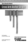
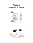
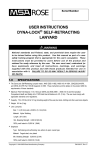
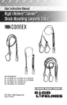
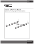
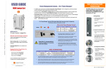
Manual 103-0052
REV. 06/14
Installation and Usage Diagram for the
Rigid Lifelines Fall Arrest Lanyard Extension Cable
ISO 9001 REGISTERED
© RIGID LIFELINES®
2
TABLE OF CONTENTS
INSTRUCTIONS FOR USE............................................................................................................... 4
MANUFACTURER............................................................................................................................4
COMPONENTS................................................................................................................................5
A. IDENTIFYING COMPONENTS OF RIGID LIFELINES FALL ARREST LANYARD EXTENSION
CABLE................................................................................................................................. 6
1) DIAGRAM.........................................................................................................................6
SPECIFICATIONS FOR CABLE ........................................................................................................ 7
USAGE NOTES............................................................................................................................ 7-8
PRODUCT INSTALLATION.......................................................................................................... 9-10
PRODUCT INSPECTION & MAINTENANCE..................................................................................... 11
CLEANING................................................................................................................................... 11
VISUAL INSPECTION CHART.........................................................................................................12
INSPECTION RECORDS................................................................................................................ 13
WARRANTY.................................................................................................................................. 16
3
INSTRUCTIONS FOR USE
USER INSTRUCTIONS
RIGID LIFELINES FALL ARREST LANYARD EXTENSION CABLE
! WARNING
r
This product must be used according to the instructions and warnings as described here.
Failure to do so could result in injury or death. All users of this product must read and
understand all of these instructions.
This product is only to be used as part of a Rigid Lifelines fall protection system. It is
never intended to be used for lifting materials or for any other uses except as specifically
outlined here in the instructions (see diagrams).
Adequate training must always be required and enforced for the proper use and care of
this product. The employer must provide adequate training.
Eliminate any workplace or safety hazards prior to use. Always remember to use proper
common sense when using any Rigid Lifelines product. Improper use of this product is
not permitted. Read and heed all manuals and all labels with this Rigid Lifelines lanyard
extension as well as with all system components shown (see diagrams).
Inspection and maintenance must always be followed for this and all fall arrest
components of the entire fall arrest system (see diagram). If this or any fall arrest
component is damaged or does not pass inspection, it must be removed from service
immediately.
IMPORTANT:
Alterations or misuse of this product or failure to follow instructions may result in serious
injury or death. If you have questions on the use, care, or suitability of this equipment for
your application, contact Rigid Lifelines at (800) 869-2080 for more information.
MANUFACTURER
Rigid Lifelines
604 Hemlock Road
Morgantown, PA 19543
Toll Free: (800) 869-2080
Fax: (610) 286-0085
www.rigidlifelines.com
[email protected]
4
COMPONENTS
IDENTIFYING COMPONENTS OF RIGID LIFELINES
FALL ARREST LANYARD EXTENSION CABLE
Model Type:
Rigid Lifelines Lanyard Extension Cable
Part Numbers:
8-0166-10 (10’ Long)
8-0166-15 (15’ Long)
8-0166-20 (20’ Long)
Proof Load:
Load Rating:
Minimum 3,600 LBS. gate strength
Minimum 5,000 LBS. breaking strength
Material:
• 1/4-in wire rope
• 2-3/16-in O-ring, zinc plated carbon steel
• ANSI rated snaphook, double action, locking snaphook,
zinc plated
5
IDENTIFYING COMPONENTS OF RIGID LIFELINES
FALL ARREST LANYARD EXTENSION CABLE
Rigid Lifelines fall arrest track or suitable anchorage
Rigid Lifelines rotating eye trolley (P/N: FA524RI) or suitable anchorage
Snap hook end of Rigid Lifelines lanyard extension cable
RIGID LIFELINES FALL ARREST LANYARD EXTENSION CABLE:
STANDARD P/N’s:
8-0166-10 (10’ Long)
8-0166-15 (15’ Long)
8-0166-20 (20’ Long)
O-ring end of Rigid Lifelines lanyard extension cable
Rigid Lifelines carabiner (P/N: 8-0175)
Rigid Lifelines self-retracting lanyard (SRL)
STANDARD P/N’s:
8-4015, 8-4020, 8-4030, 8-4031, 8-4050, or 8-4051
(or suitable SRL)
***THIS IS THE ONLY ACCEPTABLE USE FOR THIS
LANYARD EXTENSION CABLE. DO NOT DEVIATE
FROM THIS ARRANGEMENT.
Snap hook end of SRL
D-Ring portion of
Rigid Lifelines harness
(or suitable harness)
Rigid Lifelines harness
STANDARD P/N’s:
8-0161 (Universal)
8-0162 (Universal XL)
8-0163 (Universal Deluxe)
Figure 1. Lanyard Extension Cable Components Diagram
6
SPECIFICATIONS FOR CABLE
The following specifications apply to all Rigid Lifelines Fall Arrest Lanyard Extension Cables:
•
•
•
•
Steel
7x19 Strand Core
1/4” Diameter
Minimum 5,000 LBS Breaking Strength
! WARNING
r
Figure 2.
WARNING: Care must be taken to never use the Extension Cable as a choker in a tie-back
installation. It is possible when installing an Extension Cable to loop the Extension Cable
around a beam and then attach it back to itself by snapping the hook of the snap over the
cable (see Figure 2). It is also possible to loop the Extension Cable around an I-beam and
insert the snap back through the O-ring creating a choker effect (see Figure 3 on page 9).
Both of these arrangements are strictly forbidden.
USAGE NOTES
1)
All Rigid Lifelines fall protection systems meet and/or exceed all OSHA & ANSI
requirements.
2)
Read, understand and follow instructions of all component manuals and warnings
before use.
3)
Follow all current requirements of ANSI Z359 (or CSA Z259 in Canada).
4)
The following requirements do not preempt any current OSHA, Canadian, or ANSI
Z359 fall protection requirements.
7
USAGE NOTES...continued
5)
Always perform a hazard analysis before use that will identify impact hazards, swing
hazards, or any other hazards that may exist. Address and correct all hazards
before use.
6)
Inspect system before use. Check for bent, broken, or missing components.
7)
Never use system with the attachment point below the D-ring of the harness.
8)
Always have a written rescue plan that defines who will rescue and what equipment
will be used.
9)
Always use the buddy system when using fall protection (the monitor, or “buddy”
does not need to be physically on the system, just nearby supervising.) Never use
the system alone, without a monitor.
10)
On systems with rolling bridges or rotating booms, position attachment point directly
overhead of worker(s) at all times.
11)
Choose the shortest length self-retracting lanyard (SRL) available that will allow the
worker to perform his/her job function. This will reduce total fall distance and
thereby limit any possible injury during a fall. Short cable lengths will reduce the
amount of “cable cinching” on the internal SRL pulley, thereby reducing fall
distance.
For example, 50 feet of lanyard strap wrapped around a pulley will pay out more
than 10 feet of strap wrapped around a pulley before the strapping becomes tight
enough to resist the load. Fabric lanyards also stretch under load. The longer the
lanyard, the longer the stretch.
12)
If connecting hardware must be added, compatibility must be verified by a
competent person, and the connector must be certified to ANSI Z359.1-2007
(or CSA Z259 in Canada) with a minimum 3,600 LB gate strength.
13)
Per OSHA & ANSI (or CSA Z259 in Canada), designate a competent person who
can fulfill obligations of the regulations.
14)
Never deviate from the above unless you have written permission and authorization
from Rigid Lifelines.
8
PRODUCT INSTALLATION
This fall arrest self-retracting lanyard (SRL) extension cable is one component of a
complete Rigid Lifelines system. The purpose of this extension is to attach the Rigid
Lifelines SRL at a lower point.
The snap hook of this extension cable should always go upward (see Figure 3) and the
O-ring should always be hanging downward (see Figure 4).
Figure 4.
O-Ring
Figure 3.
Snaphook
The extension snap hook should always attach to the Rigid Lifelines rotating eye trolley or
other suitable anchorage. This extension should go ABOVE the SRL (see Figure 5). When using
this extension cable, the carabiner attaches the O-ring to the top of the SRL (see Figure 6).
Rigid Lifelines
Rotating Eye Trolley
(P/N: FA524RI)
Figure 6.
Rigid Lifelines
Carabiner (8-0175)
Snaphook End
Figure 5.
9
PRODUCT INSTALLATION...continued
The SRL should always be orientated as shown (the retracted portion of the cable/strap
goes upward) (see Figure 7).
Figure 7.
Rigid Lifelines
Self-Retracting Lanyard
(SRL)
The SRL snap hook always attaches to the D-ring of the harness (see Figure 8). This lanyard
extension cable should not be longer than needed. SRL instructions must be followed. This
product will lower the attachment elevation of the SRL, therefore adjust fall clearances as
required.
Snaphook End of SRL
D-Ring Portion of
Rigid Lifelines Harness
(or suitable harness)
Figure 8.
10
PRODUCT INSPECTION AND MAINTENANCE
• Reference and complete the chart on the following pages for inspections.
• The user of this extension lanyard and the user’s organization are responsible for
inspection and maintenance.
• This device should be inspected prior to each use.
• This device must be removed from service immediately if there are one or more items
that do not pass inspection.
• If this device was subject to a fall, it must be removed from service immediately. Once it
has been checked by a competent person and deemed usable, it may then be returned to
service.
• This device needs to be checked by a competent person (other than the user) once
per year or sooner if deemed necessary by the competent person.
• This chart should be completed at least once every year. If all boxes are filled in,
make a separate chart.
CLEANING
If necessary, the Rigid Lifelines Fall Arrest Lanyard Extension Cable may be cleaned prior
to use. Use a solvent based oil such as WD-40 that does not contain chlorine or chemicals
corrosive to steel or zinc. Spraying with a light oil and wiping clean will ensure that the
snaphook is free of debris and well lubricated.
11
12
Crimps Present and Not Bent, Broken, or Cracked
No Corrosion, Deformation, Cracks, or Frays
Proper SRL, Attachment Structure, and Harness
Thimbles Present and Not Bent or Broken
O-Ring Present and Not Bent, Cracked, or Broken
Readable Label
Snap Hook Not Bent or Broken
Inspector Initials
Date
VISUAL INSPECTION CHART
INSPECTION RECORDS
The following inspection log can be used for all necessary product inspections. Equipment
must be inspected prior to use by each user and if issues are found the product must be
removed from service, recertified (if applicable), or destroyed if it does not pass the
inspection. A competent person (other than the user) must inspect the equipment yearly.
Use a fall protection inspection checklist prior to each use to monitor the condition of each
piece of equipment.
Product Description
Serial #
Date in
Service
13
Inspection
Date
Employee
Name
Pass
Fail
14
15
Rigid Lifelines
604 Hemlock Road
Morgantown, PA, 19543
Toll Free: (800) 869-2080
Local: (610) 286-7200
Fax: (610) 286-0085
RigidLifelines.com
TEN-YEAR EQUIPMENT WARRANTY
Rigid Lifelines warrants the engineered track equipment, wearable end truck wheels, and Anchor Trolley™ wheels and teeth to be free from
defects in material and workmanship for a period of ten (10) years commencing on the date of installation.
TWO-YEAR EQUIPMENT WARRANTY
Rigid Lifelines warrants XSPlatforms Fall Protection components to be free from defects in material and workmanship for a period of two (2)
years commencing from the date of installation.
ONE-YEAR EQUIPMENT WARRANTY
Rigid Lifelines warrants the motorized products and drive components to be free from defects in material and workmanship for a period of one
(1) year, commencing on the date of shipment to the first retail purchaser (“Purchaser”).
Rigid Lifelines warrants all Rigid Lifelines fall protection soft goods, devices, connectors, and accessories to be free from defects in material
and workmanship for a period of one (1) year, commencing on the date of shipment to the first retail purchaser (“Purchaser”).
Rigid Lifelines is dedicated to offering superior service and quality products to all of our customers. If you would like to contact a customer
service representative, please call the following number: 1 (800) 869-2080. We will be happy to assist you in any way that we can.
These warranties do not extend to equipment which has been subject to misuse, use in excess of rated capacity, negligent operation, use
beyond Rigid Lifelines published service factors, improper installation or maintenance, adverse environments, and does not apply to any
equipment which has been repaired or altered without Rigid Lifelines written authorization. This warranty is void for any product that is
designed to deform or absorb energy during a fall event and needs to be replaced after a fall event has occurred.
Written notice of any claimed defect must be given to Rigid Lifelines within thirty (30) days after such defect is discovered. Rigid Lifelines
obligation, and Purchaser’s sole remedy under this warranty is limited to, at Rigid Lifelines discretion, the replacement or repair of the
equipment at Rigid Lifelines factory or at a location approved by Rigid Lifelines. THIS WARRANTY IS EXPRESSLY IN LIEU OF ALL OTHER
WARRANTIES WHATSOEVER WHETHER EXPRESS, IMPLIED, OR STATUTORY. SELLER MAKES NO WARRANTY AS TO THE
MERCHANTABILITY OR FITNESS FOR A PARTICULAR PURPOSE OF THE EQUIPMENT AND MAKES NO OTHER WARRANTY, EITHER
EXPRESS OR IMPLIED.
Rigid Lifelines shall not be liable, under any circumstances, for any indirect, special, or consequential damages including (but not limited to):
lost profits, increased operating costs, or loss of production. This warranty shall not extend to damages including (but not limited to): lost
profits, increased operating costs, or loss of production. This warranty shall not extend to any components or accessories not manufactured by
Rigid Lifelines (example: casters), with the exception of the components, systems, or accessories involved with XSPlatforms, and purchaser’s
remedy for such components and accessories shall be determined by the terms and conditions of any warranty provided by the manufacturer
of such components and accessories.
SERVICE POLICY
1.
Obtain as much information as possible concerning the problem through personal observation by yourself or other authorized personnel
familiar with the job and equipment: include model, serial and/or part numbers, voltages, speeds and any other special identifying
features. Be prepared to discuss the situation in detail.
2.
All authorized labor charges will be based on straight time. Hourly rates, estimated man hours, and not to exceed total dollar amount
required for corrections are to be agreed upon before authorization is given. There will be no allowances for overtime except in dire
emergencies and then only with prior approval.
3.
A verbal agreement may be reached immediately on both the method of correction and the approximate cost. A warranty authorization
number will be assigned for the specific incident. A confirming written authorization will be forwarded to the distributor.
4.
The distributor must send an itemized invoice, showing our release number or invoice number and warranty authorization number after
authorized corrections have been made. A credit memo will be issued by accounting after the invoice has been received and approved.
Warranty charges ARE NOT to be deducted from outstanding open account invoices under any circumstances.
5.
Any field corrections made prior to an authorization by Rigid Lifelines will not be accepted as a warranty charge or the responsibility
of Rigid Lifelines. Any modification to the equipment made without the prior approval of the seller will void all warranties. A verbal
authorization for modification may be obtained, in which event a warranty authorization number will be assigned for the specific
modification. A confirming written authorization will be forwarded to the distributor.
16