1
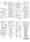
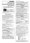
Mitsubishi Graphic Operation Terminal
A9GT-80V4 type Video input
interface module
Thank you for buying the MELSEC-GOT Series
Prior to use, please read both this manual and detailed manual thoroughly and
familiarize yourself with the product.
User’s Manual
(Hardware)
MODEL
A9GT-80V4-U
MODEL
1DM123
CODE
IB(NA)-0800167-D(0406)MEE
© 2000 MITSUBISHI ELECTRIC CORPORATION
z SAFETY PRECAUTIONS z
(Always read before starting use)
When using Mitsubishi equipment, thoroughly read this manual and the associated manuals
introduced in the manual. Also pay careful attention to safety and handle the module
properly.
These precautions apply only to the installation of Mitsubishi equipment and the wiring with
the external device. Refer to the user’s manual of the CPU module to be used for a
description of the PLC system safety precautions.
SAFETY PRECAUTIONS
classify the safety precautions into two categories:
These
"DANGER" and "CAUTION".
DANGER
Procedures which may lead to a dangerous condition and cause
death or serious injury if not carried out properly.
CAUTION
Procedures which may lead to a dangerous condition and cause
superficial to medium injury, or physical damage only, if not carried
out properly.
Depending on circumstances, procedures indicated by
CAUTION may also be linked
to serious results.
In any case, it is important to follow the directions for usage.
Store this manual in a safe place so that you can take it out and read it whenever necessary.
Always forward it to the end user.
[DESIGN PRECAUTIONS]
DANGER
z Do not bundle control lines or communication wires together with main
circuit or power lines, or lay them close to these lines.
As a guide, separate the lines by a distance of at least 100 mm (3.94 inch)
otherwise malfunctions may occur due to noise.
[INSTALLATION PRECAUTIONS]
DANGER
z Before mounting or dismounting this module to or from the GOT, always
shut off GOT power externally in all phases.
Not doing so can cause a module failure or malfunction.
CAUTION
z Use this module in the environment given in the general specifications of
the GOT User's Manual.
Not doing so can cause an electric shock, fire, malfunction or product
damage or deterioration.
z When installing this unit to the GOT, fit it to the connection interface of the
GOT and tighten the mounting screws in the specified torque range.
Undertightening can cause a drop, failure or malfunction.
Overtightening can cause a drop, failure or malfunction due to GOT or
screw damage.
[STARTUP AND MAINTENANCE PRECAUTIONS]
DANGER
z Before starting cleaning, always shut off GOT power externally in all
phases.
Not doing so can cause a module failure or malfunction.
[STARTUP AND MAINTENANCE PRECAUTIONS]
CAUTION
z Do not disassemble or modify any module.
This will cause failure, malfunction, injuries, or fire.
z Do not touch the conductive areas and electronic parts of this module directly.
Doing so can cause a module malfunction or failure.
z Exercise care to avoid foreign matter such as chips and wire offcuts entering the
module.
Not doing so can cause a fire, failure or malfunction.
z Always secure the cables connected to the module, e.g. run them in conduits or
clamp them.Not doing so can cause module or cable damage due to dangling,
moved or accidentally pulled cables or can cause a malfunction due to a cable
contact fault.
z Do not hold the cable part when unplugging any cable connected to the module.
Doing so can cause module or cable damage or a malfunction due to a cable
contact fault.
z Before handling the unit, touch a grounded metal or similar object to discharge the
static electricity from the human body.
Failure to do so may cause the unit to fail or mulfunction.
[DISPOSAL PRECAUTIONS]
DANGER
z Dispose of this product as industrial waste.
Manuals
The following manuals are relevant to this product.
Refer to the following list and order the required manuals.
Detailed Manual
Manual name
A985GOT/A975GOT/A970GOT/A960GOT User’s Manual
(Available as option)
Manual No.
(Model code)
SH-4005
(1DM099)
Relevant Manual
For relevant manual, refer to the PDF manual stored within the drawing software.
1. Overview
This User's Manual describes the A9GT-80V4 type Video input interface module
(hereinafter, A9GT-80V4).
A9GT-80V4 can display the image taken by up to 4 video cameras on the A985GOTV by connecting with A985GOT-TBA-V and A985GOT-TBD-V (hereinafter abbreviated
as A985GOT-V).
It is possible to use A985GOT-V as the vision sensor monitor.
Image data
Video camera
A985GOT-V
+
A9GT-80V4
Video camera
Camera power pack
Vision sensor (AS50VS or other)
*The camera power pack may be necessary depending on the vision sensor used.
• A9GT-80V4 cannot be mounted to the GOT other than A985GOT-V.
• For details of the system configuration, refer to the GOT-A900 Series User's
Manual(GT Works Version5/GT Designer Version5 compatible Connection System
Manual).
• For details of the video window to display on A985GOT-V, refer to GT Works
Version5/GT Designer Version5 Reference Manual.
• One of the following software packages are required for A9GT-80V4:
F version of SW5D5C-GTWORKS-E (GT Works Version5) or higher
F version of SW5D5C-GOTR-PACKE (GT Designer Version5) or higher
After opening the box, check that the following items are present.
Description
Quantity
A9GT-80V4
1
2. Specification
2.1 A9GT-80V4 specifications
Item
Color
Monochrome
Number of video input channels
Video input system
Display size [pixeles]
Video external connection method
Applicable wire size
Internal current consumption [A] (5 D VC)
Weight [kg](lb)
Maximum cable length [m](feet)
Specifications
NTSC format, PAL format (interlaced format)
EIA format, CCIR format (interlaced format)
4 channel
640x480 (possible to reduce to 320x240, 160x120)
720x480 (possible to reduce to 360x240, 180x120)
Coaxial cable
75Ω coaxial shield cable
0.19 (value for individual module)
0.15(0.33)
30 (98.42)
2.2 Coaxial cable specifications
(1) Coaxial cable
Use high frequency coaxial cable "3C-2V" "5C-2V" (conforms to JIS C 3501) for
coaxial cable.
The following shows the coaxial cable specifications.
Item
Construction
Cable diameter
Allowable bending radius
Internal conductive material
diameter
Insulation material diameter
3C-2V
5C-2V
Internal
condcuctive
Insulating
material
material
5.4mm (0.21in)
22mm (0.87 in) or more
0.5mm (0.02 in)
(Annealed copper wire)
3.1mm (0.12 in) (Polyethylene)
External conductive material
diameter
3.8mm (0.15 in) (Single annealed
copper wire mesh)
Applicable connector plug
Connector plug for 3C-2V (BNCP-3-N1-CAU is recommended.)
Sheath
External
conductive
material
7.4mm (0.29 in)
30mm (41.18 in) or more
0.8mm (0.03 in)
(Annealead copper wire)
4.9mm (0.19 in)
(Polyethylene)
5.6mm (0.22 in) (Single
annealed copper wire mesh)
Connector plug for 5C-2V
(BNC-P-5-N1-CAU is
recommended.)
(2) Connector and connector cover
• GOT connector
Use BNC connector for GOT side connector.
The following shows the connection method for BCN connector and coaxial
cable.
(a) Structure of BNC connector and the coaxial cable.
Structure of the coaxial cable
Parts of the BNC connector
Nut
Plug shell
Washer
Clamp
Outer sheath
Outer conductor
Insulating material
Internal conductive material
Gasket
Contact
(b) Connecting the BNC connector with the coaxial cable.
1) Remove the outer sheath of the end
of the coaxial cable as shown below.
15mm
(0.59inch)
Remove the outer sheath.
Clamp
Nut
Washer
Gasket
Internal conductive material
3) Cut the outer conductor, insulating
material, and internal conductive
material to specified dimensions
Clamp and
shown below.
outer conductor
Cut the outer conductor and extended
it over the end of the clamp.
Insulating material
3mm
(0.12inch)
6mm
(0.24inch)
Soldering
2) Slip a nut, a washer, a gasket, and a
clamp on the coaxial cables as
shown below, and loosen the outer
conductor.
4) Solder the contact to the tip of the
internal conductive material.
5) Insert the contact assembly in the
plug shell, and engage the plug shell
with the nut.
*1: Soldered part must not have excess solder mound.
*2: The tail end of the contact must come into close contact with the cut end of the
insulating material. The contact must not be cutting in the insulating material.
*3: Apply solder quickly so that the insulating material may not be deformed by heat.
• Connector at the video camera and vision sensor.
Use the connector applicable to the video camera and vision sensor.
(3) Precautions for cable preparation
The cable must be 30m (98.42feet) or shorter
3. Name of the Part’s and Outline Dimension Drawing
105
1)
A9GT-80V4
73
3)
CAUTION
4)
Do not mount not desmount
a module while the power is
supplied.
CH.1
FRONT SIDE
VIDEO
CH.2
CH.3
CH.4
13.3
3)
2)
43
4.35
No.
1)
2)
3)
4)
Unit:mm (inch)
Name
Connector for connection
Connector
Option module mounting screw
Rating plate
Description
Connector for connection to the A985GOT-V
Connector for mounting cable
Mounting screw to the A985GOT-V
-
4. Installation Procedure
(1) Insert the A9GT-80V4 connector
into the option module interface
at the back of A985GOT-V.
A985GOT-V back
A9GT-80V4
(2) Tighten the attachment screw to
a point within the prescribed
torque range of 39 to 59 Nycm.
To remove the unit, reverse the installation procedure.
Warranty
Mitsubishi will not be held liable for damage caused by factors found not to be the cause of
Mitsubishi; machine damage or lost profits caused by faults in the Mitsubishi products;
damage, secondary damage, accident compensation caused by special factors
unpredictable by Mitsubishi; damages to products other than Mitsubishi products; and to
other duties.
For safe use
y This product has been manufactured as a general-purpose part for general industries, and
has not been designed or manufactured to be incorporated in a device or system used in
purposes related to human life.
y Before using the product for special purposes such as nuclear power, electric power,
aerospace, medicine or passenger movement vehicles, consult with Mitsubishi.
y This product has been manufactured under strict quality control. However, when installing
the product where major accidents or losses could occur if the product fails, install
appropriate backup or failsafe functions in the system.
Country/Region Sales office/Tel
U.S.A
Mitsubishi Electric Automation Inc.
500 Corporate Woods Parkway Vernon
Hills, IL 60061
Tel : +1-847-478-2100
Brazil
MELCO-TEC Rep. Com.e Assessoria
Tecnica Ltda.
AV. Paulista 1471, Conj. 308,
Sao Paulo City, Sao Paulo State,
Brazil
Tel : +55-11-283-2423
Germany
Mitsubishi Electric Europe B.V. German
Branch
Gothaer Strasse 8 D-40880 Ratingen,
GERMANY
Tel : +49-2102-486-0
U.K
Mitsubishi Electric Europe B.V. UK
Branch
Travellers Lane, Hatfield, Herts., AL10
8XB,UK
Tel : +44-1707-276100
Italy
Mitsubishi Electric Europe B.V. Italian
Branch
Centro Dir. Colleoni, Pal. Perseo-Ingr.2
Via Paracelso 12, 20041 Agrate B.,
Milano, Italy
Tel : +39-039-6053344
Spain
Mitsubishi Electric Europe B.V. Spanish
Branch
Carretera de Rubi 76-80
08190 - Sant Cugat del Valles,
Barcelona, Spain
Tel : +34-93-565-3131
France
Mitsubishi Electric Europe B.V. French
Branch
25 Boulevard des Bouvets, F-92741
Nanterre Cedex, France
TEL: +33-1-5568-5568
South Africa
Circuit Breaker Industries LTD.
Tripswitch Drive, Elandsfontein Gauteng,
South Africa
Tel : +27-11-928-2000
Country/Region Sales office/Tel
Hong Kong
Ryoden Automation Ltd.
10th Floor, Manulife Tower, 169 Electric
Road, North Point, HongKong
Tel : +852-2887-8870
China
Ryoden Automation Shanghai Ltd.
3F Block5 Building Automation
Instrumentation Plaza 103 Cao Bao Rd.
Shanghai 200233 China
Tel : +86-21-6475-3228
Taiwan
Setsuyo Enterprise Co., Ltd.
6F., No.105 Wu-Kung 3rd.RD, Wu-Ku
Hsiang, Taipei Hsine, Taiwan
Tel : +886-2-2299-2499
Korea
HAN NEUNG TECHNO CO.,LTD.
1F Dong Seo Game Channel Bldg.,
660-11, Deungchon-dong Kangsec-ku,
Seoul, Korea
Tel : +82-2-3660-9552
Singapore
Mitsubishi Electric Asia Pte, Ltd.
307 ALEXANDRA ROAD #05-01/02,
MITSUBISHI ELECTRIC BUILDING
SINGAPORE 159943
Tel : +65-6473-2308
Thailand
F. A. Tech Co.,Ltd.
898/28,29,30 S.V.City Building,Office
Tower 2,Floor 17-18 Rama 3 Road,
Bangkpongpang, Yannawa,
Bangkok 10120
Tel : +66-2-682-6522
Indonesia
P.T. Autoteknindo SUMBER MAKMUR
Jl. Muara Karang Selatan Block A Utara
No.1 Kav. No.11 Kawasan Industri/
Pergudangan Jakarta - Utara 14440
Tel : +62-21-663-0833
India
Messung Systems Put,Ltd.
Electronic Sadan NO:111 Unit No15,
M.I.D.C BHOSARI,PUNE-411026
Tel : +91-20-712-2807
Australia
Mitsubishi Electric Australia Pty. Ltd.
348 Victoria Road, PostalBag, No 2,
Rydalmere, N.S.W 2116, Australia
Tel : +61-2-9684-7777
HEAD OFFICE : 1-8-12, OFFICE TOWER Z 14F HARUMI CHUO-KU 104-6212, JAPAN
NAGOYA WORKS : 1-14, YADA-MINAMI 5-CHOME, HIGASHI-KU, NAGOYA, JAPAN
When exported from Japan, this manual does not require application to the Ministry
of Economy, Trade and Industry for service transaction permission.
Specifications subject to change without notice.
Printed in Japan on recycled paper.