1
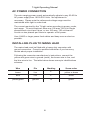
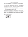
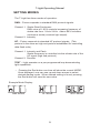
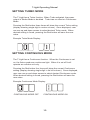
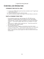
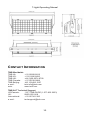
T-Light
User Manual
Revised 102814
T-Light Operating Manual
TABLE OF CONTENTS
Safety Information....................................................................................... 3
Preparation for Use..................................................................................... 5
DMX Setup.................................................................................................. 8
Controller Operation................................................................................... 11
Technical Specifications............................................................................. 12
2
T-Light Operating Manual
SAFETY INFORMATION
Important: This product is for professional use only! It is not
for household use.
The T-Light presents risks of injury due to fire, heat, electric shock,
ultraviolet radiation, and falling. Flashing lights are known to trigger
epileptic seizures in persons who are photosensitive. Read this
manual before powering or installing the fixture, follow the safety
precautions listed below and observe all warnings in this manual and
printed on the fixture.
PREVENT ELECTRICAL SHOCK
•
•
•
•
•
•
•
•
Always disconnect the fixture from AC power and allow the flash
capacitors to discharge for 5 minutes before handling the fixture,
lamp, fuse, and when not in use.
Only remove rear cover to change fuse. There are no userserviceable parts inside. Always return cover to the fixture before
powering.
Always ground (earth) the fixture electrically.
Use only a source of AC power that complies with local building and
electrical codes and has both overload and ground fault protection
inside.
Fixture has an IP 34 rating protecting it from dust and nozzled water
only.
Replace the lamp only as described and have it replaced by a TMB
service technician.
Use of a Ground Fault Circuit Interrupt is recommended for all
installations.
Should any kind of liquid or material penetrate the unit, terminate
operation immediately, then unplug the unit from its power outlet
and contact TMB for service.
AVOID UV RADIATION, BURNS, FIRE
•
•
•
•
•
•
Never operate the fixture with the front glass open, missing, or
damaged.
Do not stare directly into the light. Never look at an exposed lamp
while lit.
Replace the lamp when it becomes defective or worn out.
When replacing the lamp, allow the fixture to cool for at least 20
minutes before opening the fixture or removing the lamp.
Never attempt to bypass the fuse. Always replace defective fuses
with ones of the specified type and rating.
Verify that the power feed cable is rated for the current draw of all
connected fixtures.
3
T-Light Operating Manual
•
•
•
•
•
•
•
Keep all combustible materials (e.g., fabric, wood, paper) at least 1
meter (40 inches) away from the fixture. Keep flammable materials
away from the fixture.
Do not illuminate surfaces within 1 meter (40 inches) of the fixture.
Provide minimum clearance of 1 meter (40 inches) around fixture.
Never place filters or other materials over the front glass cover.
The exterior of the fixture can reach temperatures up to 120˚C
(248˚F). Allow the fixture to cool for at least 20 minutes before
handling.
Check power connections frequently for proper connections.
Improper connection may cause fire due to unit’s high power
consumption.
PREVENT MECHANICAL SHOCKS
•
•
•
When suspending the fixture above ground level, verify that the
structure can hold at least 10 times the weight of all installed
devices.
Verify that all external covers and rigging hardware are securely
fastened and use an approved means of secondary attachment
such as a safety cable.
Block access below the work area whenever installing or removing
the fixture.
PREVENT SEIZURES
•
•
•
Do not operate the fixture near stairways.
Provide advance notice that strobe lighting is in use.
Avoid extended periods of continuous flashing, particularly at
frequencies of10 to 20 flashes per second.
4
T-Light Operating Manual
PREPARATION FOR USE
UNPACKING
The T-Light comes with the following items:
• Xenon lamp (packed separately)
• Mounting Bracket (installed)
• User manual
Packing materials protect fixture and lamp during shipment. Retain
all packing materials and always use it to transport fixture and lamp.
Never ship the fixture with xenon lamp installed; always ship
separately.
Upon receipt, ensure there is no damage to the packaging, fixture, or
lamp tube. Any problems should be reported to the shipping
company.
UNPACKING LAMP
Important: Do not touch lamp with bare hands! Unpack
and repack lamp by pulling/pushing on the lamp coils and
not the glass!
Remove tube cap, then pull out lamp and bubble wrap together.
Unroll lamp from bubble wrap. Before installing in fixture, remove
reflective panels on both ends of the strobe to expose the lamp
terminals.
LAMP INSTALLATION
When installing lamp in fixture, be sure to insert the lamp coils in the
fixture’s terminal blocks behind the removable reflector panels, and
connect the lamp’s drain wire to the spring clamp on one side of the
reflector.
REPACKING LAMP FOR SHIPMENT
Remove the lamp from fixture and place it back in the bubble wrap in
the enclosed tube. Place the fixture glass-side down, flat in the
bottom of the case.
5
T-Light Operating Manual
AC POWER CONNECTION
The auto-ranging power supply automatically adjusts to any 50-60 Hz
AC power supply from 190 to 250 Volts. No adjustment is
necessary. Please note the referenced voltage range must be
maintained while light is under load.
The current required by the T-Light varies according to power, mode,
and usage. To avoid overload, allow one 100 amp, 220 Volt Single
phase branch circuit per fixture, or two 100 amp, 120 volt branch
circuits on two phases per fixture to operate at full power.
Use 4 AWG or larger power feed cables and keep runs as short as
possible.
INSTALLING PLUG TO MAINS LEAD
The mains lead must be fitted with a heavy duty connector with
ground connection. Consult a qualified electrician if you have any
doubts about proper installation.
Following the connector manufacturer’s instructions, connect the
yellow and green wire to ground (earth), the brown wire to live, and
the blue wire to live. The table below shows some pin identifications
schemes.
Wire
Pin
Marking
Screw color
brown
live
“L”
yellow or brass
blue
live
“L”
silver
yellow/green
ground
“G”
green
6
T-Light Operating Manual
INSTALLING THE FIXTURE
Warning: Always use a secure means of secondary
attachment!
The T-Light may be installed in any orientation.
Before installing, verify that:
• The attachment hardware is in good condition and designed to
bear at least 10 times the fixture’s weight.
• The structure can support at least 10 times the weight of all
installed fixtures, clamps, cables, auxiliary equipment, etc.;
• The fixture will be located at least 1 meter (40 in) away from the
surface to be illuminated, at least 1 meter (40 in) from any
combustible materials, and away from flammable materials.
• The clearance around the fixture is at least 1 meters (40 in).
• No one should be located under the work area while fixture is
installed.
IMPORTANT:
1) Work on a stable platform, clamp or fasten the fixture securely
to the structure.
2) Install a safety cable around the support and bracket.
3) Loosen the mounting bracket and adjust the fixture to the
desired angle.
4) Connect and arrange the power and data cables.
DMX FEATURES
The Quasar unit can be remotely controlled using industry standard
DMX-512 protocol. In DMX Mode, Channel 1 dictates the Strobe Rate.
DMX values from 1-90% increase the frequency of strobe flash from 124 Hz. Above 90% activates Continuous Mode (constant light output).
Channel 2 accepts values which dictate flash intensity above 10%.
DMX SETUP
SETTING THE START CHANNEL
The control address, also known as the START channel, is the first
channel used to receive instructions from the controller. The address
7
T-Light Operating Manual
may be any channel from 1 to 511 and is set on the Digital Control
found inside clear door on rear of fixture.
The T-Light uses 2 channels in DMX control mode. For independent
control, each fixture must be assigned its own address and nonoverlapping control channels. Two or more T-Lights may share the
same address if individual control is not required.
•
Pressing the Red button two times will show the current starting
DMX address.(display showing 3 digits)
Once displayed, the operator can use up and down arrows to select
desired starting address (tapping the arrow buttons will change values
one number at a time; holding an arrow button will change values
rapidly). When desired setting is found, pressing the Red button will
save the new value.
Example Address Display
8
T-Light Operating Manual
SETTING MODES
The T-Light has three modes of operation:
DMX – Fixture responds to standard DMX protocol signals.
Channel 1: Strobe Rate/Continuous
DMX value of 1-90% controls increasing frequency of
strobe rate from 1 Hz to 24 Hz. Above 90% activates
continuous mode (constant light output)
Channel 2: Intensity
HF – Fixture responds to standard HF protocol signals. (This
protocol is the same as high end protocol established for controlling
data flash units).
Channel 1: Intensity and Flash
Strobe frequency is controlled via the refresh rate of the
HF signal (high end protocol)
Channel 2: Duration
TEST – Light operates on a pre-programmed loop demonstrating
light capabilities.
•
Pressing the Red button one time will show the current MODE.
Once displayed, user can use up and down arrows to select
desired starting mode. When desired setting is found, pressing
the Red button will save the new value.
Example Mode Display:
DMX MODE
HF MODE
9
TEST MODE
T-Light Operating Manual
SETTING TURBO MODE
The T-Light has a Turbo function. When Turbo activated, the power
output in Strobe Mode is doubled. Turbo has no effect on Continuous
Mode.
Pressing the Red button three times will show the current Turbo setting
(display showing single digit in center column). Once displayed, user
can use up and down arrows to select desired Turbo mode. When
desired setting is found, pressing the Red button will save the new
value.
Example Turbo Mode Display:
SETTING CONTINUOUS MODE
The T-Light has a Continuous function. When the Continuous is set
on, the fixture produces continuous light. When it is set off it will
operate as a strobe unit only.
Pressing the Red button four times will show the current Continuous
setting (display showing single digit in far left column). Once displayed,
user can use up and down arrows to select desired Continuous mode.
When desired setting is found, pressing the Red button will save the
new value.
Example Continuous Mode Display:
CONTINUOUS MODE OFF
CONTINUOUS MODE ON
10
T-Light Operating Manual
CONTROLLER OPERATION
CONNECTING DATA LINK
1) Connect the DMX data input from the controller to the T-Light 5-pin
input (male) socket.
2) Connect additional fixtures output-to-input.
3) Insert a termination plug in the output of the last fixture on the link.
DATA CONNECTION TIPS
• Use shielded twisted-pair cable designed for RS-485 devices:
standard microphone cable cannot transmit control data reliably
over long runs. 24 AWG cable is suitable for runs up to 300 meters
(1000 ft.). Use heavier gauge cable and/or an amplifier for longer
runs.
• Never use a Y-splitter cable to split the link. To split the serial link
into branches, use a signal splitter.
• Do not overload the link
• Terminate the link by installing a termination plug in the output
socket of the last fixture. The termination plug, which is a male XLR
plug with a 120 ohm, 0.25 watt resistor soldered between pins 2
and 3, “soaks up” the control signal so it does not reflect and cause
interference.
11
T-Light Operating Manual
TECHNICAL SPECIFICATIONS
LAMP
Type (proprietary):
Frequency of continuous mode:
Flash tube type:
Colour temperature:
85 KW long-arc xenon tube
100/120 Hz
Special T-Light tube
6000˚ Kelvin
PERFORMANCE
Intensity control:
Adjustable flash frequency:
0-100%
0-20/24 Hz
ELECTRONIC & SAFETY
Electronic overdrive protection:
Overheating protection:
SELF-TEST:
Indicator LEDs:
max 3.5 seconds
110˚C, self-resetting
Preprogrammed
Red: POWER
Yellow: MODE/PROTECTION
Green: DATA
CONTROL SYSTEM
2 Channel:
DMX mode
HF mode
No. of DMX starting addresses:
Connection type:
Controllability:
CH1: Freq.; CH2: Intensity
CH1: Intensity; CH2: Duration
Max. 511
5-Pin XLR
DMX 512, HF protocol
POWER SUPPLY
Nominal mains voltage:
Continuous:
Turbo::
190-250 VAC, 50-60 Hz
340A (3.5 sec)
32A (11.5 sec)
FIXTURE / HOUSING:
Protection from breaking flash tube: Spring supports
Fixing:
Trigger clamp
Corrosion protection:
Stainless steel
Unit dimensions (HxWxD):
15” x 33” x 10” / 38 x 84 x 25 cm
Shipping Dimensions (HxWxD):
21” x 41” x 19” / 53 x 104 x 48 cm
Unit weight :
39 lb. / 17.7 kg
Shipping weight:
54 lb. / 24.5 kg
(Specifications and features are subject to change without notice)
12
T-Light Operating Manual
CONTACT INFORMATION
TMB Worldwide
TMB LA:
TMB NY:
TMB UK:
TMB Canada:
TMB Beijing:
e-mail:
web:
+1 818.899.8818
+1 201.896.8600
+44 (0)20.8574.9700
+1 519.538.0888
+86 10.8492.1587
[email protected]
www.tmb.com
TMB 24/7 Technical Support
US/Canada:
1 877.TMB.DUDE (1 877.862.3833)
UK:
0800.652.5418
International:
+1 818.794.1286
e-mail:
[email protected]
13