1
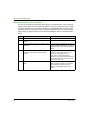
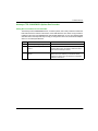
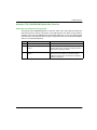
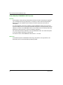
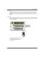
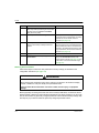
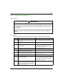
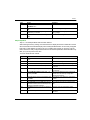
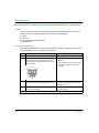
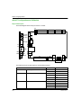
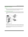
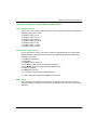
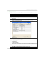
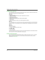
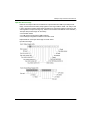
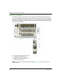
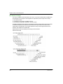
FTB IP67 Devices
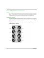
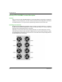
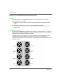
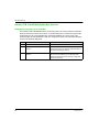
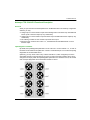
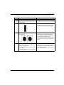
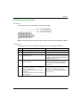
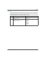
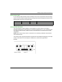
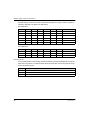
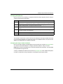
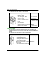
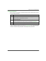
Socket
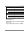
Pin
Default Setting
Optional Configurable Setting
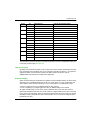
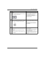
1
4
state of sensor 1
state of actuator 1
2
diagnostic for sensor 1 or actuator 1
state of sensor 9 or actuator 9
4
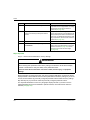
state of sensor 2
state of actuator 2
2
diagnostic for sensor 2 or actuator 2
state of sensor 10 or actuator 10
4
state of sensor 3
state of actuator 3
2
diagnostic for sensor 3 or actuator 3
state of sensor 11 or actuator 11
4
state of sensor 4
state of actuator 4
2
diagnostic for sensor 4 or actuator 4
state of sensor 12 or actuator 12
4
state of sensor 5
state of actuator 5
2
diagnostic for sensor 5 or actuator 5
state of sensor 13 or actuator 13
4
state of sensor 6
state of actuator 6
2
diagnostic for sensor 6 or actuator 6
state of sensor 14 or actuator 14
4
state of sensor 7
state of actuator 7
2
diagnostic for sensor 7 or actuator 7
state of sensor 15 or actuator 15
4
state of sensor 8
state of actuator 8
2
diagnostic for sensor 8 or actuator 8
state of sensor 16 or actuator 16
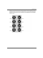
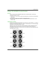
2
3
4
5
6
7
8
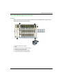
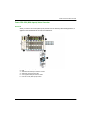
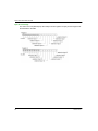
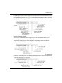
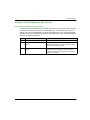
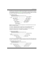
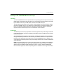
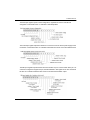
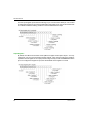
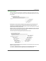
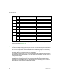
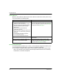
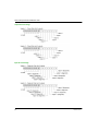
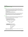
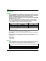
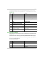
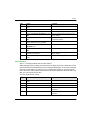
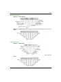
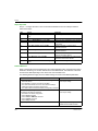
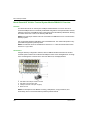
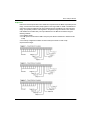
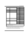
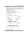
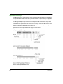
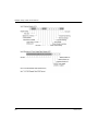
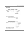
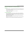
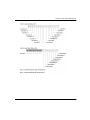
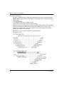
The pin 2 data is reported in the second input register for to the FTB 1CN16CM0 splitter box in the
input process image (see page 83).
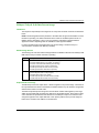
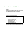
Input/Output Parameters
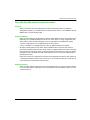
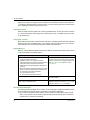
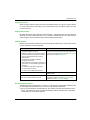
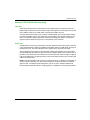
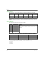
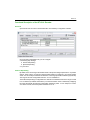
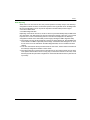
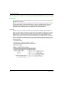
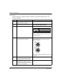
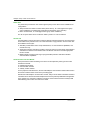
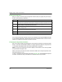
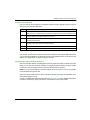
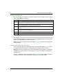
You have the ability to configure pin 4 and pin 2 on each of the 8 sockets to support either a sensor
input or an actuator output. (You may also configure pin 2 on each channel to provide diagnostics
for the input or output on pin 4 of that socket; this is the default setting for pin 2 on each socket.)
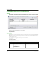
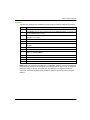
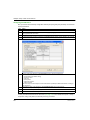
Two 8-channel parameters in the Module editor of the Advantys configuration software are
provided to define up to 16 I/O channels in any combination.
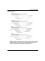
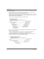
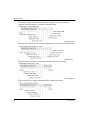
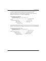
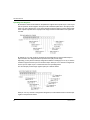
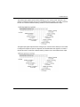
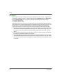
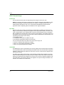
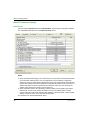
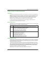
To configure the signal on pin 4 of any of the 8 sockets as an input signal, set the associated bit in
the Input/Output at Pin 4 parameter to 0. If you set a value of 1 to that bit, pin 4 on that channel is
configured as an output.
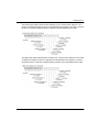
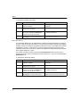
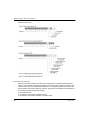
To configure the signal on pin 2 of any of the 8 sockets as an input signal, make sure that the
Input/Diagnostic parameter is set to 0. Then set the associated bit in the Input/Output at Pin 2
parameter to 0. (0 is the default setting for this parameter on all channels.) If you set a value of 1
to that bit, pin 4 on that channel is configured as an output.
80
31006709 7/2013