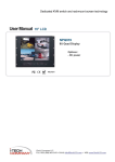
1
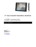
■
USER
MANUAL
User Manual
19” LCD
NPQ919
9U Quad Display
Options :
- DC power
User Manual
Contents
< Part. 1 > NPQ919
1.1
1.2
1.3
Package Content
Structure Diagram & Dimension
Installation
P.1
P.1 - 2
P.3
< Part. 2 > Specifications / OSD
2.1
2.2
Product Specifications
On-screen Display Operation ( OSD )
P.4 - 5
P.6
< Part. 3 > Options
3.1
48V, 24V or 12VDC power
P. 7
< Part. 4 > Quad Display Connection & Operation
4.1
4.2
4.3
4.4
4.5
4.6
4.7
QD Connection
QD ALARM Connection & Operation
QD Remote Control Connection & Operation
QD OSD Operation
QD On-screen Menu
QD VCR Operation
QD Specification
P.8
P.9 - 10
P.11 - 15
P.16
P.17 - 19
P.20
P.20
User Manual
<Part 1 >
< 1.1 > Package Content
NPQ919 unit X 1
- 6ft VGA cable X 1
- Power adapter X 1
- Power cord X 1
-
< 1.2 > Structure Diagram
1
P.1
2
User Manual
< 1.2 > Dimension
Model
NPQ919
NPQ919
Product Dimension
(W x D x H)
Packing Dimension
(W x D x H)
Net
Weight
Gross
Weight
480 x 68.5 x 399 mm
18.9 x 2.7 x 15.7 inch
583 x 124 x 529 mm
23 x 4.9 x 20.8 inch
9.5 kg
20.9 lbs
12.5 kg
27.5 lbs
P. 2
User Manual
< 1.3 > Installation
Step 1
■
■
Mount the display panel with M6 screw set.
M6 screw x 8pcs required (Left & right side).
M6 screw sets are not provided.
Step 2
■ Fix the LCD into the
rack.
P. 3
User Manual
<Part 2 >
< 2.1 > Product Specifications
LCD
Panel
NPQ919
Manufacturer
AUO
Panel Size ( diagonal )
19-inch TFT color LCD
Display pixel ( dots x lines )
1280 x 1024
Brightness ( typ. )
250
Contrast Ratio ( typ. )
1000:1
Color
16.7 M
Viewing Angle ( L/R/U/D )
85/85/80/80
Response Time ( ms )
5
Dot pitch ( mm )
0.294
Display Area ( mm )
376.32H x 301.06V
Surface treatment
Haze 25%, Hard-coating
Surface hardness
3H
Backlight Type
LED
MTBF ( hrs )
30,000
Video
Connectivity
Analog
Power
Power Supply
Range
Auto-sensing 100 to 240VAC,
50 / 60Hz
Power Consumption
Screen display ON
25W or less
Power saving mode
4W or less
Power button OFF
1W or less
Regulatory
Safety Approval
Environmental
Conditions
Operating
Storage
VGA
Analog 0.7Vp-p
cUL, FCC & CE, RoHS
Temperature
0 to 50°C degree
Humidity
20~90%, non-condensing
Temperature
-5 to 60°C degree
Humidity
5~90%, non-condensing
Shock
10G acceleration (11ms duration)
Vibration
5~500Hz 1G RMS random
P. 4
User Manual
Physical
Specification
Product ( W x D x H )
480 x 68.5 x 399 mm
18.9 x 2.7 x 15.7 inch
Packing ( W x D x H )
583 x 124 x 529 mm
Net Weight
23 x 4.9 x 20.8 inch
9.5 kgs / 20.9 lbs
Gross Weight
Applicable
Format
DVI-D / VGA Input
12.5 kgs / 27.5 lbs
PC Signal
1280 x 1024 x 60 / 75Hz
1280 x 960 x 60Hz
1280 x 760 x 60 / 75Hz
1152 x 864 x 75Hz
1024 x 768 x 60 / 70 / 75Hz
848 x 480 x 60Hz
800 x 600 x 60 / 72 / 75Hz
720 x 400 x 70Hz
640 x 480 x 60 / 72 / 75Hz
640 x 400 x 70Hz
640 x 350 x 70Hz
P. 5
User Manual
< 2.2 > On-screen Display Operation ( OSD )
P. 6
NPQ919
User Manual
<Part 3 >
< 3.1 > Options : DC Power
Model
12V
24V
48V
Input voltage:
12-Volt
24-Volt
48-Volt
Input range:
9 ~ 18V
18 ~ 36V
36 ~ 75V
- No load
50 mA
50 mA
50 mA
- Full load
4950 mA
2450 mA
1220 mA
Output voltage:
12-Volt
12-Volt
12-Volt
Output current:
4.16A
4.16A
4.16A
84%
85%
85%
Input rating
Input current
Output rating
Effi ciency
P. 7
User Manual
<Part 4 >
< 4.1 > QD Connection
NPQ919
1. VCR in :
This BNC connector is connected to video output from VCR/DVR. A pre-recorded quad screen signal from a tape can be
played back through a VCR/DVR and displayed on the video output channels. Push the VCR button (#2) to switch the
device to VCR Playback mode.
2. VCR out :
This BNC connector is to be connected to the Video in from your VCR/DVR. It will only provide a quad screen video to
ensure an un-interrupted video recording for all four cameras. The display video is not affected by the control panel.
3. Terminations :
These impedance switches are used to provide proper termination for each camera input. These switches toggle between 75Q and Hi-Z impedance. Incorrect termination will degrade the quality of the video signal. All video inputs not
“looped through” to another device, the corresponding switches need to be set to 75Q termination position. If another
device is connected to video out loop through connector set the corresponding termination switch to Hi-Z position. Any
device connected to the video out loop through connectors needs to be confi gure to 75Q video termination. The factory
default termination setting is 75Q.
4. Ch1 In, Ch2 In, Ch3 In, and Ch4 In Video IN connectors :
These BNC connectors are used to connect to the video out from camera. Four cameras can be connected to these connectors to form a quad screen in the following mapping order.
1
2
3
4
5. Ch1 Out, Ch2 Out, Ch3 Out, and Ch4 Out Video Loop through connectors :
These connectors are used to loop video signals from each camera out to other devices.
P. 8
User Manual
< 4.2 > QD ALARM Connection & Operation
1. ALARM I/O :
This female type 9 pin D-sub connector is used for alarm sensor input and alarm output control connections. It provides
Normal Open and Normal Close contacts for alarm out control.
The Alarm Hold Time can be configured from 0 second to 99 minutes through system Setup menu.
2. VCR Connection for Tape Recording Start and Stop Control :
Connecting the contacts of VCR RECORD and STOP switch to the alarm output NC and NO contacts will allow you to use
an ordinary VCR to record for longer period of time. Combined with alarm sensor detection, the VCR will record only when
an alarm sensor is activated.
*. If more than one sensor have been trigged, VCR will start to record after the last trigged event. *. In order to make use of
the alarm called full screen display function, the VIDEO IN connector from the VCR has to be connected to LIVE monitor
connector of the device. If more than one sensor are trigged, VCR will then record all the events in full screen mode
accordingly.
P. 9
User Manual
< 4.2 > QD ALARM Connection & Operation
NPQ919
3 Sensor Activated Alarm
The unit is equipped with 4 alarm sensor inputs. If any alarm is activated:
■
■
■
the built-in buzzer and the alarm output control relay contact will be activated.
the quad will switch the corresponding channel indicator LED to blinking mode.
a warning message depending on different models will be displayed as follows:
Above mentioned alarm can be cleared by any of the following: 1. Connecting the Alarm Reset In contact, pin #5, of the
female type 9 pin D-sub connector (#8) to GND. 2. The Alarm Duration time elapses. 3. If the device is operated under
Security Lock ON mode, Push Lock button for 2 seconds to disable the function then push any button in the front panel.
4 Video Loss Alarm
Loss of video at any input is automatically detected by the device. The device will:
■
■
■
Activate the built-in buzzer.
Switch the corresponding channel indicator LED to blinking mode.
Display warning message on quad screen:
■
The warning message and the buzzer can be
cleared by pushing Lock button (#2) for more than 4
seconds if the device is operated under Security lock On
mode, or pushing any button on the front panel if the device
is operated under Security lock OFF mode.
P.10
User Manual
< 4.3 > QD Remote Control Connection & Operation
P.11
User Manual
< 4.3 > QD Remote Control Connection & Operation
NPQ919
The device can be controlled via the male type 9 pin D-sub/RS-232 connector to a computer using ASCII code.
1. Pin assignment of the male type 9 pin D-sub connector:
When a computer is used to control this device through a RS-232 port, pin 6, 7, 8, and 9 must be disconnected to
prevent connecting the VCC and GND signals from the device to the computer. A RS-232 port only uses pin 1, 2,
and 3 for control signal transmission.
2. A terminal or computer can be connected to the male type 9 pin D-sub connector on the real panel from it RS232 port to control this device using standard, uppercase ASCII codes.
2.1 The ASCII command codes for the quad are listed in the table below. The transmission protocol is 1200baud rate, 8 data bit, 1 start bit, 1 stop bit, and no parity.
P.12
User Manual
< 4.3 > QD Remote Control Connection & Operation
*1. In order to control the device to operate in Zoom mode, the computer has to first send
command code ” to switch the signal source from camera to VCR/DVR, at this time the device will
automatically zoom channel 1 video from VCR/DVR to full screen. User can then input a corresponding channel code to zoom any other specifi c channel. Input the corresponding channel code again to
put the specific channel to freeze mode and send the code again to clear the freeze mode.
Example: Input GE, (GE) B, (GE) C, and (GE) D for zooming the video signal in channel 1 to 4 from
VCR/DVR. Input “A”, “B”, “C”, “D” again to freeze the specifi c channel. Send command code “G”
again to get back to Live input mode.
*2. Computer has to send out command code “H” continuously for 2 seconds to switch the device between security lock ON and OFF mode. If any alarm is activated under security lock ON mode, the
device has to send out command code “H” continuously for more than 4 seconds to clear the alarm.
*3. Setup menu is switched ON by sending VCR/DVR and Lock button codes together.
*4. Text Select and Cursor Control functions can be performed only under menu Setup mode.
2.2 Right after computer/terminal has sent out the above mentioned control command code to the device, the
device will respond with following status code back to computer through RS-232 port:
Status
Code
Quad Status
Status
Code
Quad Status
EF
Device in Quad mode
DE
CH1 in Sequence mode
EE
CH1 in Freeze mode
DD
CH2 in Sequence mode
ED
CH2 in Freeze mode
DB
CH3 in Sequence mode
EC
CH1 & 2 in Freeze mode
D7
CH4 in Sequence mode
EB
CH3 in Freeze mode
CF
Quad display in Sequence mode
EA
CH1 & 3 in Freeze mode
E9
CH2 & 3 in Freeze mode
E
CH1 in Full screen mode
E8
CH1, 2, & 3 in Freeze mode
D
CH2 in Full screen mode
E7
CH4 in Freeze mode
B
CH3 in Full screen mode
E6
CH1 & 4 in Freeze mode
7
CH4 in Full screen mode
E5
CH2 & 4 in Freeze mode
E4
CH1, 2 & 4 in Freeze mode
E3
CH3 & 4 in Freeze mode
E2
CH1, 3, & 4 in Freeze mode
XX-7F
Security lock ON
CH2, 3, & 4 in Freeze mode
XX-3F
Buzzer & Security lock ON (Stop)
E0
Attach to above code
XX-DF
CH1, 2,3, & 4 in Freeze mode
P.13
Buzzer/VCR ON
User Manual
< 4.3 > QD Remote Control Connection & Operation
NPQ919
2.3 The confi guration of the status code for both normal and alarm operations:
There are total 2 bytes of the status codes. Byte one, the fi rst 8 bits, shows the current status of the operation
modes that the unit is in. Byte two, the second 8 bits, shows the current status of the alarm operations of the
unit.
BYTE 1: Status code for normal operation modes
P.14
User Manual
< 4.3 > QD Remote Control Connection & Operation
BYTE 2: Status code for alarm operations: The first 4 bits show the sensor activated alarm status of each
channel; next 4 bits show the video loss alarm status of each channel. The digit “1” means alarm event is
detected, and “0” means no alarm event is detected.
P.15
User Manual
< 4.4 > QD OSD Operation
NPQ919
1 Lock: Security locks out button. Push this button for 2 seconds to enable control panel lock out function. Push this
button again for 2 seconds to disable the function.
2 VCR: Push this button to enter into VCR Playback/Zoom operation. In this mode, the output video is displaying the
video signal from VCR. When operated in Full Screen display mode, push select buttons (#5) to zoom any specific
camera signal pre-recorded on the tape in quad format. Push the select button (#5) again to freeze the expanded
picture on the screen.
#1, #2 Setup buttons: Push these two buttons simultaneously to get into Menu Setup mode and display page 1 of
system setup menu. Push these two buttons simultaneously again to display page 2 of the setup menu. Use page 1 to
program time/date and camera title and page 2 to confi gure alarm operations. Under menu setup mode, Channel
Select buttons (#5) are used for cursor control and text selection to program the setup menu. Push the setup buttons
simultaneously again to save the setting. Push the setup buttons fourth time to get back to ordinary operation mode.
Setup buttons (#1, #2)
Push once
Push twice
Push the third time
Push the fourth time
3
4
5
Function
Page 1 menu for time / date / title programming
Page 2 menu for alarm confi guration
Save the settings
CH Select buttons (#5)
UP, DOWN
< , >
Text Selection
Cursor Control
Text Selection
Cursor Control
Yes / No
Exit setup mode, back to normal
SEQ.: Push this button to enable full page auto sequencing mode. Push this button again to disable it.
: Push this button to switch between Quad/ Full Screen display mode.
buttons: When operated in Quad mode, these buttons are used to freeze any specific camera by
pushing the corresponding button. When operated in Full Screen display mode, these buttons are used to select
specific camera to be displayed in full screen.
These buttons are also used as cursor control and text select keys under Setup menu mode.
P.16
User Manual
< 4.5 > QD On-screen Menu
Right after the unit is turned on, The monitor will display the last setting on the Setup Menu.
1. Page 1 of the Setup Menu - Display Setting
Push Setup buttons (#1, #2) simultaneously to display the Setup Menu on the screen. There are total two pages in the
Setup Menu. Page 1 is used to program TIME, DATE, and camera TITLE. Page 2 is used to program Alarm Operations.
Under this mode, channel selection buttons (#5) on the front panel are used for cursor control and text selection. Use the
cursor control buttons "<" and ">" to move the cursor to the location as desired to program, and use the text select buttons "˄" and "˅" to choose the right alphanumeric character to program.
Page 1: Setting the TIME, DATE, TITLE, and DWELL time:
1.1 TITLE setup:
The Title menu permits the setup of separate titles for each video channel. 8 characters may be entered for each video
channel. The available alphanumeric characters are:
0, 1, 2, 3, 4, 5, 6, 7, 8, 9, A, B, C, D, ............ X, Y, Z, . , :, - , / , < ,>,˄,˅,space
1.2 DWELL Time setup:
The Dwell time menu permits setting the dwell time for all cameras and the Quad Screen on the LIVE output channel.
The menu shows a table of all cameras and associated dwell time. Dwell time can be programmed by setting a number
between 00 to 99 for each channel in the menu.
■ 01 through 99: Adds the camera input to the auto switching SEQUENCE, with the corresponding dwell time in
seconds.
■
00:
Skips the camera input in the auto switching SEQUENCE.
1.3 TIME/DATE setup:
Time and date information can be displayed on the video output channel through both LIVE and QUAD connector. Bottom of page 1 is used to set the values of time and date and also to enable or disable the display at each output channel.
The date and time will display in the “MM-DD-YYYY HH:MM:SS” format for NTSC model and “DD-MM-YYYY
HH:MM:SS” format for PAL model.
1.4 TITLE/TIME/DATE disable and enable on LIVE and QUAD video output channel:
The Title/Time/Date display on each output channel can be enabled or disabled by setting ON or OFF in the corresponding entry.
P.17
User Manual
< 4.5 > QD On-screen Menu
NPQ919
2 Page 2 of the setup menu- Alarm Setting
Push Setup buttons (#1, #2) simultaneously and push (#1) button again to display page 2 of the setup menu on the
screen. This Alarm Setting menu is used to set the desired alarm confi guration like sensor type, sensor sensitivity, alarm
hold duration, and buzzer.
2.1 Sensor Type:
The machine will fi rst detect the type of the sensor connected to the corresponding channel. The result will be displayed in
the fi rst column following each channel number. They can be on either OPEN or CLOSE. The menu then allows user to
enter a desired type of the sensor for each channel in next column. NO means Normally Open. NC means Normally
Close.
Then the menu will allow user to enable or disable sensor input for each channel in the next column. ON will enable the
contact to detect the alarm status from the input. OFF will ignore the sensor input and disable the alarm detection from the
input. Last column on this part of the menu shows the result of the actually detected sensor type and the desired confi
guration. If the setup type of the sensor is different from the actually connected type of sensor, a blinking “?” message will
display. In this case, the buzzer will be activated when you exit the setup operation.
2.2 Alarm Sensitivity:
Alarm sensitivity can be programmed to different extent by setting the period of the trigged pulse detected by the sensor.
The available settings are 100ms, 200ms, 300ms, 400ms, 500ms, 600ms, 700ms, and 800ms.
2.3 Alarm Hold Duration:
The alarm hold duration can be set from 00 second to 59 minutes. The duration can be set to non-stop by choosing “>>“.
In this mode, the activated alarm can only be reset by connecting the alarm reset contact to ground.
2.4 Buzzer:
The device has a build-in buzzer to signal a detected alarm through sound. User can choose to disable the buzzer by
setting it to OFF.
2.5 V-Loss Alarm:
This entry is used to enable or disable the video loss alarm. The device automatically detects loss of video at any input if
this entry is set to ON. User can choose to disable this feature by setting it to OFF for applications like video conferencing or others that will need constant video source switching.
2.6 V-Loss Relay Control:
The device is equipped with an alarm controlled relay, which can be activated by both sensor trigged alarm and video loss
alarm. This entry allows user to disable the relay activation from a loss of video in any camera input.
3 Save the settings and exit Setup Menu mode
Push (#1) button again will allow you to save the settings and go back to the normal operation mode and show a quad
display on the screen.
P.18
User Manual
< 4.5 > QD On-screen Menu
4: The setup menu can be reset to factory setting by pushing the Setup buttons (#1, #2) and power on the quad
simultaneously. The factory setting is as follows:
CH
TITLE
QUAD
1
CH 1
2
CH 2
3
CH 3
4
CH 4
LIVE VIDEO FREEZE
VIDEO OUT:
TITLE:
TIME: 23 : 10 : 10
DATE: 12 - 25 - 2003
DWELL
LIVE
ON
ON
ON
TIME
03S
03 S
03 S
03 S
03 S
ON
QUAD
ON
ON
ON
ALARM SETTING
CH
SENSOR
1
OPEN
2
OPEN
3
OPEN
4
OPEN
SENSITIVITY:
DURATION:
BUZZER:
V-LOSS ALARM:
V-LOSS RELAY:
TYPE
NO
NO
NO
NO
STATUS
ON
ON
ON
ON
0.3 S
30 S
ON
ON
OFF
5. The Quad Display Mode
5.1 Push Quad display button (#4) to switch between Quad screen and Full screen display mode. Right after you
turn on the system, the unit is in the quad mode and displays cameras 1-4.
5.2 Use page 1 of the Setup menu to turn the Title display ON/OFF on each channel and also enable and disable
the Time and Date display on LIVE and QUAD output channels.
5.3 Under Quad screen mode, push channel select button to freeze each camera input.
6. The Full Screen Display Mode
6.1 Push Quad button (#4) to OFF to enter Full screen display mode. Under this mode, you may call up any spe
cifi c channel in full screen by simply pushing the corresponding channel selection button.
6.2 Push the Quad button (#4) to ON to return to the quad mode.
7. The Still Frame Display Mode
7.1 If the still screen mode is desired, fi rst turn the quad display button (#4) to ON to set the unit to display in the
quad mode. At this time you may press any of the four channel selection buttons (#5) to freeze the
corresponding channel.
7.2 Under Zoom On VCR playback mode, if the unit is showing quad screen, pushing the channel selection but
tons (#5) will call up the specifi c channel to display in full screen. Push the same channel selection button
again to freeze that channel in full screen.
8. The Auto-Sequence Mode
Push the Sequence button (#3) to ON to set the device to work as a sequencer. Under this mode, the display sequence fi
rst starts with a quad screen and then continues to display each camera input in full screen, and then gets back to quad
screen and so on. Press the Sequence button (#3) to OFF to release this mode.
P.19
User Manual
< 4.6 > QD VCR Operation
NPQ919
Zoom on VCR playback operation:
Push VCR button (#2) to ON will switch the device to VCR playback mode. Under this mode, if the device is on quad
display mode, a pr-recorded quad display video in the tape will be shown on the screen. If the device is in Full screen
display mode, push any channel select buttons (#5) will select and expand the corresponding quadrants of the prerecorded video to full screen display.
< 4.7 > Quad Display Specification
Item
Model Number
Number of Color
Imaging System
Resolution
Refresh Rate
Description
QD (NTSC)
16.7 M
NTSC
1024 x 525
60
50
Video Input
Camera Input
VCR Input
Video Output Live Monitor
Loop Through Out
1.0 Vpp, 75 Ohm x 4
1.0 Vpp, 75 Ohm x 1
1.0 Vpp, 75 Ohm x 1
1.0 Vpp, 75 Ohm x 4
VCR Output
Auto Gain Control
Time / Date
On Screen Display
Camera Title
2 x Zoom On
Playback
Display
QUAD
Format
FULL
SEQUENCY
Dwell Time
Alarm Inputs
QD (PAL)
16.7 M
PAL
1024 x 625
1.0 Vpp, 75 Ohm x 1
Yes
Yes
Yes
8 Character Title
Ye s
Yes
Ye s
Ye s
0 to 99 Sec Adjustable
Selectable NO/NC Contacts x 4
Relay Outputs
NO/NC contacts x 1: 1A @DC24V Max.
Alarm Hold Tim
Built-in Buzzer
Key Lock
1 Sec to Non-stop
Yes
Ye s
i-Tech Company LLC
TOLL FREE: (888) 483-2418
EMAIL: [email protected]
WEB: www.iTechLCD.com
P.20