1
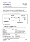
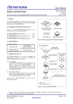
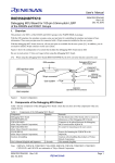
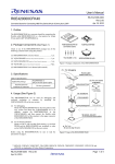
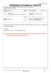
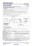
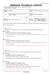
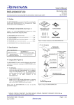
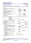
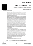
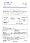
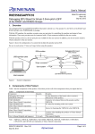
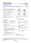
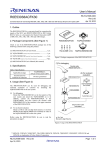
User's Manual
R20UT2344EJ0100
Rev.1.00
Feb 14, 2013
R0E5563TEDMB00
Debugging MCU Board for 120-pin 0.5mm-pitch LQFP
of the RX63T Group
1. Overview
The debugging MCU board R0E5563TEDMB00 (hereafter referred to as “this product”) is for MCUs of the RX63T
group in the PLQP0120KA-A package.
With the E20 emulator, the emulator occupies some user port pins for controlling the emulator and output of trace
information. These user port pins must be connected with a 38-pin connector installed on the user system.
With this product, however, all user port pins are available for the user system. In addition, you do not need to install a
38-pin connector on the user system.
Figure 1 shows the configuration of a system that includes this product and the E20.
Be sure to read section 7, Notes on Usage, before using this product.
E20 emulator
Debugging MCU board
(this product)
USB interface cable
YQPACK
(provided with this
product)
38-pin connector
User system
NQPACK
(provided with this product)
Host computer
Figure 1
System Configuration
2. Package Components
The package of this product consists of the following items. Check that you have all of the components when you
unpack the box.
Table 1 Package Components
Component
Debugging MCU board common part
(R0E5563TEVKZ00)
Converter board (R0E5563TEPFKE0)
YQPACK120SD
(from Tokyo Eletech Corporation)
NQPACK120SD
(from Tokyo Eletech Corporation)
YQ-GUIDE-S1
(from Tokyo Eletech Corporation)
Cautions in handling
User’s Manual (English and Japanese)
Quantity Remarks
1
For the dimensions, refer to section 6, Dimensions of This Product.
1
1
For the dimensions, refer to section 6, Dimensions of This Product.
Connector to be placed between this product and the NQPACK.
1
IC socket for mounting on the user system
4
Screws for fastening the YQPACK to the NQPACK.
1
Cautions when handling the products of Tokyo Eletech Corporation
1 for each This manual (English)
Note: NQPACK, YQPACK, YQSOCKET, YQ-GUIDE, HQPACK, TQPACK, TQSOCKET, CSSOCKET,
CSPLUG/W, and LSPACK are trademarks of Tokyo Eletech Corporation.
R20UT2344EJ0100 Rev.1.00
Feb 14, 2013
Page 1 of 8
R0E5563TEDMB00
User's Manual
Important
CAUTION
Caution to Be Taken for Disposal:
Penalties may be applicable for incorrect disposal of this waste, in accordance with your national
legislation.
European Union regulatory notices:
The WEEE (Waste Electrical and Electronic Equipment) regulations put responsibilities on
producers for the collection and recycling or disposal of electrical and electronic waste. Return of
WEEE under these regulations is applicable in the European Union only. This equipment
(including all accessories) is not intended for household use. After use the equipment cannot be
disposed of as household waste, and the WEEE must be treated, recycled and disposed of in an
environmentally sound manner. Renesas Electronics Europe GmbH can take back end of life
equipment, register for this service at “http://www.renesas.eu/weee”.
Cautions to Be Taken for Handling This Product:
• Take full care not to touch any parts or cause short circuits on this product.
• Protect this product from excessive physical shock.
• Do not alter this product. If any alteration is attempted, this product will no longer be supported.
• The MCU installed on this product is only for use in debugging. Do not remove the MCU from
the board to use it for other purposes.
• For purchasing the NQPACK120SD, YQPACK120SD and HQPACK120SD, contact the
following:
Tokyo Eletech Corporation http://www.tetc.co.jp/e_index.htm
Cautions to Be Taken for Turning On the Power:
• Do not apply a power voltage that is beyond the range guaranteed for the MCU.
• Only supply power to this product and connected parts after having connected all cables.
Caution for Use Temperature:
This product is to be used in an environment with a maximum ambient temperature of 35°C.
Care should be taken that this temperature is not exceeded.
European Union regulatory notices
This product complies with the following EU Directives.
Environmental Compliance and Certifications:
• Waste Electrical and Electronic Equipment (WEEE) Directive 2002/96/EC
R20UT2344EJ0100 Rev.1.00
Feb 14, 2013
Page 2 of 8
R0E5563TEDMB00
User's Manual
3. Specifications
Table 2 shows the functional specifications of this product.
Table 2 Specifications of This Product
Item No. Item
Specification
1
MCU for use
•RX63T-group MCUs in PLQP0120KA-A packages
2
The MCU type name
•R5F563TEBDFB
installed on this product
(ROM: 512 Mbytes, RAM: 48 Kbytes, E2 DataFlash: 32 Kbytes )
3
Power supply
• For 3-V MCU products:
- Power (VCC = PLLVCC = VCC_USB) at 2.7 to 3.6 V is supplied from the
user system.
- Power (AVCC0 = AVCC) at 3.0 to 3.6 V, or 4.0 to 5.5 V is supplied from the
user system.
- Power (VREFH0) at 3.0 to AVCC0, or 4.0 to AVCC0 is supplied from the
user system.
- Power (VREF) at 3.0 to AVCC, or 4.0 to AVCC is supplied from the user
system.
•For 5-V MCU products:
- Power (VCC = PLLVCC) at 4.0 to 5.5 V is supplied from the user system.
- Power (VCC_USB) at 3.0 to 3.6 V is supplied from the user system.
- Power (AVCC0 = AVCC) at 4.0 to 5.5 V is supplied from the user system.
- Power (VREFH0) at 4.0 to AVCC0 is supplied from the user system.
- Power (VREF) at 4.0 to AVCC is supplied from the user system.
•The state of power supply can be monitored through the test pins (TP1 for
VCC, TP2 for GND, TP3 for VCC_USB, TP4 for AVCC, TP5 for AVCC0,
and TP6 for VREFH0).
4
System clock (EXTAL)
•A maximum of 14 MHz clock signals are supplied from the user system.
Note 1:
Use this product at a voltage (VCC > VPOR) that doesn't make the MCU enter the state of power on reset.
4. Reset Circuit
Figure 2 shows the reset circuit, with the level on the RES# pin pulled up by a 510-kΩ resistor.
R0E5563TEVKZ00
UVCC
38-pin connector (CN3)
R0E5563TEPFKE0
MCU (IC1)
RES#
YQSOCKET120SDF(CN3)
R18
0Ω
Pin 12 (RES#)*2
R19
510kΩ
Pin 9 (RES#)*1
Notes*: 1. The number indicated is the pin number of the 38-pin connector (CN3).
2. The number indicated is the pin number of the YQSOCKET120SDF (IC1).
Figure 2 Reset Circuit in This Product
R20UT2344EJ0100 Rev.1.00
Feb 14, 2013
Page 3 of 8
R0E5563TEDMB00
User's Manual
5. Connection
To connect this product and the user system, follow the
procedure below.
(1) For debugging
Flexible cable of
the E20 emulator
The R0E5563TEDMB00 (this product) can be used for
debugging and on-board evaluation in common by
mounting the NQPACK120SD on the user system.
(1) For debugging
1. Mount the NQPACK120SD on the user system.
Be sure to check that the location of pin 1 is correct.
2. Install the YQPACK120SD after checking for a match
with the position of pin 1 for the NQPACK120SD.
Then use the YQ-GUIDE-S1 to affix the
YQPACK120SD to the NQPACK120SD.
● Do NOT use the screws included with the
YQPACK120SD for fixing the YQPACK120SD.
● Do NOT use the screwdriver included with the
NQPACK120SD for fixing the YQ-GUIDE-S1.
That is used only for the HQPACK120SD. Note
that you need to provide your own screwdriver.
3. Connect the R0E5563TEDMB00 after checking for a
match with the position of pin 1 for the YQPACK120SD.
4. Install the connector of the flexible cable from the E20
emulator to the 38-pin connector on the
R0E5563TEDMB00.
Hold the R0E5563TEDMB00 while connecting the
cable to avoid imposing heavy pressure on the 38-pin
connector of the R0E5563TEDMB00.
(2) For on-board evaluation
5. Mount an MCU with on-chip flash memory and the
HQPACK120SD (not included) in order on the
NQPACK120SD on the user system.
R0E5563TEDMB00
4
R0E5563TEVKZ00
38-pin
connector
R0E5563TEPFKE0
(back side:
YQSOCKET120SDF)
3
(2) For on-board
evaluation
Use a flat-bladed
screwdriver.
YQ-GUIDE-S1(×4)
HQPACK120SD
(not included)
YQPACK120SD
2
MCU
NQPACK120SD
5
1
120-pin, 0.5-mm pitch
(PLQP0120KA-A) foot pattern
indicates pin 1 in this example.
Check that the pin-1 positions on the foot pattern and
all of the components are correctly aligned.
Figure 3
Connection of the User System and This
Product
Before using the R0E5563TEDMB00, be sure to read section 7, Notes on Usage.
WARNING
Warnings to Be Taken for Connection:
• Always switch OFF the emulator, this product, and the user system before connecting or disconnecting
the emulator. Failure to do so will create a FIRE HAZARD and will damage the emulator, this product,
and the user system.
• Make sure that the connectors on both ends of the user-system interface cable are facing the right way
relative to the user-side connector on the emulator and the 38-pin connector on this product,
respectively. Incorrect connection will create a FIRE HAZARD and will damage the emulator, this
product, and the user system.
CAUTION
Cautions to Be Taken for Mounting the NQPACK:
• Check the locations of pin 1 before mounting the NQPACK.
• The tightening torque must be no greater than 0.054 N•m. If the applied torque is not accurately
measurable, stop tightening when the force required to turn the screw (YQ-GUIDE-S1) becomes
significantly greater than that required at the start of tightening. Tightening a screw too much may break
the screw hole of the NQPACK or lead to a faulty connection by cracking solder on the NQPACK side.
• Failure of conduction during operation may be due to a crack in the solder for the NQPACK. Check
conduction with a tester and re-solder the NQPACK as required.
R20UT2344EJ0100 Rev.1.00
Feb 14, 2013
Page 4 of 8
R0E5563TEDMB00
User's Manual
6. Dimensions of This Product
Figures 4 shows the dimensions and reference foot pattern of this product (R0E5563TEDMB00).
Ø 2.20
50.00
TP3
VCC_USB
TP1
VCC
CN3
1
2
37
38
R0E5563TEVKZ00 REV.A
73
72
108
IC1 109
144
1
37
36
POWER
X1
3.00
TP2
GND
25.00
TP4
AVCC
12.00
AVCC0
12.00
TP5
TP6
VREFH0
50.00
3.00
18.30
3.00
12.00
12.00
25.00
0.65x29=18.85
19.00
15.60
0.25
0.50
15.60
19.00
Unit[mm]
Figure 4
Reference Foot Pattern and Dimensions of This Product (R0E5563TEDMB00)
R20UT2344EJ0100 Rev.1.00
Feb 14, 2013
Page 5 of 8
R0E5563TEDMB00
User's Manual
7. Notes on Usage
READ the following warnings before using this product. Incorrect operation will damage this product and the user
system. The USER PROGRAM will be LOST.
Notes on Connecting the Debugging MCU Board:
• Cables must not be connected or removed while the power is on.
• Before connecting this product and the user system, check that the pin 1 locations on both sides are
correctly aligned with each other.
Note on Rewriting the Flash Memory:
• The number of times that the flash memory in the MCU installed on this product can be programmed is
limited. If an error in erasure occurs during debugging, replace this product.
Notes on Debugging:
• This product is only usable for debugging when it is connected to the user system.
• Debugging by this product alone is not supported.
Note on Starting the Debugger and Selecting the MCU Type:
• Select the MCU type for use in the device name section of the [Initial Settings] dialog box on initiation of
the debugger.
Note on Differences between the MCU to be Debugged and This Product:
• The ROM size of the MCU installed in this product is 512 KB. Note that if the ROM size of the MCU to
be debugged is smaller than that of this product, access can be made to the differential area.
Note on the Port PF0 and PF1:
• The port PF0 and PF1 are unavailable when using this product. Note that these ports will be unconnected
on the user system.
Notes on Designing the User System:
• Pull the levels on the EMLE pin down to 4.7 kΩ to 10 kΩ.
• Pull the levels on the MD pin up to 4.7 kΩ to 10 kΩ, and select the single-chip mode.
• The output of the reset circuit of the user system must be open collector.
Note on the Flash Programming Software (Flash Development Toolkit, Renesas Flash Programmer, etc.):
• Do not use the flash programming software when using this product.
Note on the Writing the On-chip Flash Memory Mode:
• If the debugger has an exclusive mode for flash writing (e.g. “writing the on-chip flash memory mode” of
the High-performance Embedded Workshop), do not use the mode.
Note on the A/D Converter:
• The characteristics of the A/D converter differ from those of actual MCU because there are a converter
board and other devices between the MCU and the user system.
Note on the Hot Plug-in Function:
• Do not use the hot plug-in function when using this product.
Note on Communication Interface:
• Use this product via JTAG communication.
R20UT2344EJ0100 Rev.1.00
Feb 14, 2013
Page 6 of 8
R0E5563TEDMB00
User's Manual
Precautions
This product is only intended for use in a laboratory environment under ambient temperature and humidity
conditions. A safe separation distance should be used between this and any sensitive equipment. Its use outside the
laboratory, classroom, study area or similar such area invalidates conformity with the protection requirements of
the Electromagnetic Compatibility Directive and could lead to prosecution.
The product generates, uses, and can radiate radio frequency energy and may cause harmful interference to radio
communications. However, there is no guarantee that interference will not occur in a particular installation. If this
equipment causes harmful interference to radio or television reception, which can be determined by turning the
equipment off or on, you are encouraged to try to correct the interference by one or more of the following
measures;
• ensure attached cables do not lie across the equipment
• reorient the receiving antenna
• increase the distance between the equipment and the receiver
• connect the equipment into an outlet on a circuit different from that which the receiver is connected
• power down the equipment when not in use
• consult the dealer or an experienced radio/TV technician for help
NOTE: It is recommended that wherever possible shielded interface cables are used.
The product is potentially susceptible to certain EMC phenomena. To mitigate against them it is recommended that
the following measures be undertaken;
• The user is advised that mobile phones should not be used within 10m of the product when in use.
• The user is advised to take ESD precautions when handling the equipment.
This product does not represent an ideal reference design for an end product and does not fulfill the regulatory
standards for an end product.
8. Warranty
1. This product comes with a one-year warranty after purchase.
Should the product break down or be damaged while you’re using it under normal condition based on its user’s
manual, it will be repaired or replaced free of cost.
2. Note, however, that if your product's fault or damage is raised by any one of the following causes, the warranty is
void.
a) Misuse or abuse of the product or its use under other abnormal conditions
b) Improper handling of the product after purchase, such as dropping of the product when it is transported or moved
c) Other pieces of equipment connected to the product
d) Fire, earthquakes, thunderbolts, floods, or other natural disasters or abnormal voltages, etc.
e) Modifications, repairs, adjustments, or other acts made to the product by other than Renesas Electronics
Corporation.
In the above cases, contact your local distributor.
If your product is being leased, consult the leasing company or the owner.
R20UT2344EJ0100 Rev.1.00
Feb 14, 2013
Page 7 of 8
If the requirements shown in the "WARNING"
sentences are ignored, the equipment may
cause death or heavy wound.
If the requirements shown in the "CAUTION"
sentences are ignored, the equipment may cause
personal injury or damage to the products.
Renesas Tools Website http://www.renesas.com/tools
Send any technical inquiries to http://www.renesas.com/inquiry.
All trademarks and registered trademarks are the property of their respective owners.
© 2013 Renesas Electronics Corporation and Renesas Solutions Corp.
Colophon 2.2