1
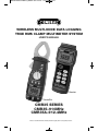
CMR35 Manual FINAL4_020911:awb 2/9/11 11:54 AM Page 1
WIRELESS MULTI-NODE DATA LOGGING
TRUE RMS CLAMP MULTIMETER SYSTEM
USER’S MANUAL
Receiver
Transmitter
CMR35 SERIES
CMR35–910MHz
CMR35A–912.4MHz
Please read this manual carefully and thoroughly before using this product.
CMR35 Manual FINAL4_020911:awb 2/9/11 11:54 AM Page 2
TABLE OF CONTENTS
Introduction . . . . . . . . . . . . . . . . . . . . . . . . . . . . . . . . . . . . . . . . . . . . . . . . . . . . . . . . . . . 3
Safety Precautions . . . . . . . . . . . . . . . . . . . . . . . . . . . . . . . . . . . . . . . . . . . . . . . . . . 3
Key Features . . . . . . . . . . . . . . . . . . . . . . . . . . . . . . . . . . . . . . . . . . . . . . . . . . . . . . . . . . . 4
What’s in the Case . . . . . . . . . . . . . . . . . . . . . . . . . . . . . . . . . . . . . . . . . . . . . . . . . . . . . . 4
Product Overview . . . . . . . . . . . . . . . . . . . . . . . . . . . . . . . . . . . . . . . . . . . . . . . . . . . . 5 – 6
Operating Instructions . . . . . . . . . . . . . . . . . . . . . . . . . . . . . . . . . . . . . . . . . . . . . . . 7 – 29
Making Basic Measurements with the Transmitter . . . . . . . . . . . . . . . . . . . . . . . . 7
Measuring Current . . . . . . . . . . . . . . . . . . . . . . . . . . . . . . . . . . . . . . . . . . . . . . . 7 – 8
Measuring Voltage . . . . . . . . . . . . . . . . . . . . . . . . . . . . . . . . . . . . . . . . . . . . . . . 8 – 9
Measuring Resistance . . . . . . . . . . . . . . . . . . . . . . . . . . . . . . . . . . . . . . . . . . . . . . . 9
Testing Diodes and Checking Continuity . . . . . . . . . . . . . . . . . . . . . . . . . . . . . 9 – 10
Measuring Frequency. . . . . . . . . . . . . . . . . . . . . . . . . . . . . . . . . . . . . . . . . . . 10 – 11
Making Relative Measurements . . . . . . . . . . . . . . . . . . . . . . . . . . . . . . . . . . . . . . 11
Using the Receiver with the Transmitter . . . . . . . . . . . . . . . . . . . . . . . . . . . . . . . . 12
Setting the Transmitter’s Transmission Span and ID Code (Channel) . . 12 – 15
Operating the Receiver. . . . . . . . . . . . . . . . . . . . . . . . . . . . . . . . . . . . . . . . . . 16 – 21
Reading, Holding, Storing and Recalling Data . . . . . . . . . . . . . . . . . . . . 16 – 18
Setting Alarms and Setpoints . . . . . . . . . . . . . . . . . . . . . . . . . . . . . . . . . 18 – 19
Setting the Clock . . . . . . . . . . . . . . . . . . . . . . . . . . . . . . . . . . . . . . . . . . . . . . . 20
Setting the Receiver’s Transmission Span and ID Code (Channel) . . . . 20 – 21
Data Logging with a Computer . . . . . . . . . . . . . . . . . . . . . . . . . . . . . . . . . . . 22 – 29
Installing the Software and a USB Driver . . . . . . . . . . . . . . . . . . . . . . . . 22 – 23
Verifying the Installation . . . . . . . . . . . . . . . . . . . . . . . . . . . . . . . . . . . . . . . . . 23
Using the Software. . . . . . . . . . . . . . . . . . . . . . . . . . . . . . . . . . . . . . . . . . 24 – 29
Specifications. . . . . . . . . . . . . . . . . . . . . . . . . . . . . . . . . . . . . . . . . . . . . . . . . . . . . 30 – 32
FCC Radio Frequency Interference Compliance Disclosure . . . . . . . . . . . . . . . . . . . . . 33
Operation and Maintenance Tips. . . . . . . . . . . . . . . . . . . . . . . . . . . . . . . . . . . . . . . . . . 34
Optional Accessories . . . . . . . . . . . . . . . . . . . . . . . . . . . . . . . . . . . . . . . . . . . . . . . . . . . 34
Warranty Information . . . . . . . . . . . . . . . . . . . . . . . . . . . . . . . . . . . . . . . . . . . . . . . . . . . 34
Return for Repair Policy . . . . . . . . . . . . . . . . . . . . . . . . . . . . . . . . . . . . . . . . . . . . . . . . . 35
2
CMR35 Manual FINAL4_020911:awb 2/9/11 11:54 AM Page 3
INTRODUCTION
Thank you for purchasing General Tools & Instruments’ CMR35 Series Wireless Data
Logging Clamp Multimeter System. Please read this user’s manual carefully and
thoroughly before using the instrument.
There are two CMR35 systems: The CMR35 system operates at 910MHz and the
CMR35A system operates at 912.4MHz. The basic CMR35 system consists of one
CMR35T clamp meter/ transmitter, one CMR35R data logging receiver (operating at the
same frequency), a USB cable and an installation CD containing data logging software
and a set of USB drivers. Up to six transmitters on different channels can be interfaced
to one receiver operating at the same frequency. The system is designed for use by
industrial maintenance, repair and operations (MRO) professionals.
Used alone or with the receiver, the multimeter’s clamp-type transmitter can measure AC
or DC voltages up to 600 Volts, AC or DC currents up to 600 Amperes, electrical resistances
up to 4MΩ, and the frequency of AC voltages and currents up to 100 kHz. Autoranging is
automatic for all measurements. The transmitter can also verify the integrity of diodes and
perform yes/no checks of continuity between any two points of a circuit.
When a transmitter and receiver are wirelessly connected—at a maximum distance of
328 ft. (100m), with no obstructions in between—measurements made by the transmitter
can be displayed remotely and in real time on the receiver’s display. Measurements also can
be time-stamped by the included data logging software and transferred from the receiver to
a Windows™ computer via a USB cable. As the computer stores the measurements, they can
be viewed in the software’s Monitor window in real time. Measurement logs also can be
viewed and saved on the computer as tabular or graphical data.
The CMR35 system is powered by four “AA” batteries (two each for the transmitter
and receiver).
SAFETY PRECAUTIONS
• WARNING
To prevent electrical shock, fire or damage to the multimeter:
• Never attempt to measure voltages above 600 Volts or currents above 600 Amperes.
• Make sure the transmitter’s function switch is in the correct position for the
parameter to be measured.
• Check that the transmitter’s probes fit snugly in their jacks whenever using them to
make measurements.
• Keep your hands under the guard ring (see Fig. 1) when using the clamp.
• Before switching functions, remove the probes from the circuit under test, and
remove conductors from the jaws of the clamp.
• Before conducting resistance tests, make sure the power to the circuit under test
has been switched off.
• Never use the multimeter in the rain or snow, or with wet hands.
• Do not use the transmitter if its case or probes have been cracked or damaged.
3
CMR35 Manual FINAL4_020911:awb 2/9/11 11:54 AM Page 4
KEY FEATURES
• Measures AC and DC voltages, AC and DC currents, resistances, and frequency of
AC voltages and currents
• AC and DC voltage and current measurements are “true RMS” readings
• Includes software and USB cable that connect receiver to a PC, enabling
measurements from up to six transmitters to be displayed, logged (stored on)
an SD card, and viewed in Excel on a Windows computer
• Software also can calculate electricity (power) charges for up to six loads
(single-phase or 3-phase motors, heaters or other heavy loads)
• Autoranging
• Supports setting of Hi and Lo alarm setpoints
• Tests diodes and performs continuity checks
• Wireless receiver works at up to 333 ft. (100m) with no objects between it
and transmitter
• Stores and recalls minimum and maximum readings
WHAT’S IN THE CASE
The two main components of the CMR35 Series system—the clamp meter/transmitter
(CMR35T transmitter) and the data logging receiver (CMR35R receiver)—come in a
protective hard carrying case along with a pair of probes, four “AA” batteries (two
each for the transmitter and receiver), a USB cable, an installation CD containing
Excel-compatible data logging software and a USB driver, and this user’s manual.
4
CMR35 Manual FINAL4_020911:awb 2/9/11 11:54 AM Page 5
PRODUCT OVERVIEW
Before using the transmitter and receiver together, learn how to make some basic
measurements using the transmitter unit alone. To begin, familiarize yourself with
Figures 1 and 2. Fig. 1 shows the transmitter unit’s controls, indicators and jacks. Fig. 2
shows the symbols used by the transmitter’s liquid-crystal display, as well as their
positions.
햲 Clamp
햳 Clamp tips/opening
햴 Guard ring
햵 Clamp trigger
햶 Function switch
햷 HOLD button
햸 햹 REL./SEL. button
햺 TX ON button
햻 FUNCTION button
햽 SET button
햾 Nameplate
햿 COM (negative or ground)
input jack
헀쏋
+ (positive) input jack
헁 Liquid-crystal display
Fig. 1. The transmitter’s controls, indicators and jacks
5
CMR35 Manual FINAL4_020911:awb 2/9/11 11:54 AM Page 6
Symbol
Description
Transmission ID code (Channel) setting
Antenna blinking while in the process of transmitting
Transmission span selection; options are
2, 10, 30, 60, and 120 seconds
Lit in DC voltage measurement mode
Lit in AC voltage measurement mode
Lit when measuring negative polarity
Autoranging on indicator
Lit in continuity check mode
Lit in diode check mode
Data hold indicator
Lit in relative mode or when zeroing display
Lit when battery voltage is low
Lit in frequency measurement mode
Unit of resistance measurement
Unit of voltage measurement
Unit of current measurement
Measured value
Fig. 2. Symbols used on the transmitter’s liquid-crystal display
6
CMR35 Manual FINAL4_020911:awb 2/9/11 11:54 AM Page 7
OPERATING INSTRUCTIONS
MAKING BASIC MEASUREMENTS WITH THE TRANSMITTER
As you make measurements, be aware that pressing the HOLD button on the transmitter
(callout 6 of Fig. 1) temporarily stores (memorizes) the displayed reading. This feature
comes in handy when making measurements under low-light conditions or in tight
spaces (under counters, in crawl spaces or attics, or inside electrical panels) where the
display is out of sight. In these cases, press the HOLD button to freeze the reading
(causing the letters “D-H” to appear on the top line of the display). Then move the
transmitter to where its display can be read more easily. To release the held reading,
press the HOLD button again.
MEASURING CURRENT
To measure the AC current flow through a conductor, move the function switch to the
A
~ position, squeeze the clamp trigger to open the clamp, and place one conductor only
in the center of the clamp’s jaws, as shown in the following figure. Read the value once
it stabilizes.
It is good practice to measure the
current carried by the “hot” line
BLACK OR
(usually a black or red wire).
RED (HOT)
Measurements of current through
WIRE
the return or neutral conductor
(usually a white wire) may be
misleading because the return may
be used by other circuits.
To measure the current drawn by an
appliance with a fixed power cord,
General recommends using an
industry-standard AC line splitter, as
shown in the following figure. To
purchase an AC line splitter from
General, see p. 31.
In AC current measurement mode, the
CMR35T selects a 0 to 400A measurement
range unless the input is greater than 400A.
In this case, the unit automatically switches
to a full-scale range of 0 to 600A.
When you have finished making measurements, move the function switch to the
OFF position.
To measure the DC current flow through a
conductor, move the function switch to the
position, squeeze the clamp trigger to
open the clamp, and place one conductor
only in the center of the clamp, as shown in the earlier figure.
7
CMR35 Manual FINAL4_020911:awb 2/9/11 11:54 AM Page 8
In DC current measurement mode, the CMR35T selects a 0 to 400A measurement range
unless the input is greater than 400A. In this case, the unit automatically switches to a
full-scale range of 0 to 600A.
Read the value after it stabilizes. If the
symbol appears at the left of the measured
value, as shown in Fig. 2, the current flow is opposite the direction indicated by the
polarity marks on the clamp. To reverse the flow, unclamp the meter, rotate the clamp
180º, and then reclamp the jaws around the line.
When you have finished making measurements, move the function switch to the OFF
position.
MEASURING VOLTAGE
To measure the DC voltage between two points in a circuit, move the function switch
to the
position. Press the REL./SEL. button until the
symbol does not appear
at the left of the display. Plug the rubber-covered end of the black probe into the COM
terminal of the transmitter unit and the rubber-covered end of the red probe into the
unit’s
terminal. Then touch the metal ends of the black and red probes to the points
whose potential difference you wish to measure.
• WARNING
• To avoid exposing yourself to a harmful or fatal voltage and damaging the
transmitter, make sure that the potential you are attempting to measure is less
than 600VDC.
As in current measurement mode, the CMR35T automatically chooses the narrowest
measurement range that includes the tested value. The five available full-scale ranges
are 0 to 400mV, 0 to 4V, 0 to 40V, 0 to 400V, and 0 to 600V.
Read the measured value once it stabilizes. If the
symbol appears to the left of the
value, the measured voltage is negative. When you have finished making
measurements, move the function switch to the OFF position.
To measure the AC voltage between two points in a circuit, move the function switch
to the
position. Press the REL./SEL. button (callout 7/8 of Fig. 1) until the
symbol appears at the left of the display. Plug the rubber-covered end of the black probe
into the COM jack of the transmitter (callout 13 of Fig. 1) and the rubber-covered end of
the red probe into the transmitter’s
jack (callout 14). Then touch the metal ends of
the black and red probes to the points whose potential difference you wish to measure.
8
CMR35 Manual FINAL4_020911:awb 2/9/11 11:54 AM Page 9
• WARNING
• To avoid exposing yourself to a harmful or a fatal voltage and damaging the
transmitter, make sure that the potential you are attempting to measure is less
than 600VAC.
As in current measurement mode, the CMR35T automatically chooses the narrowest
measurement range that includes the tested value. The four available full-scale ranges
are 0 to 4V, 0 to 40V, 0 to 400V, and 0 to 600V.
Read the measured value once it stabilizes. When you have finished making measurements, move the function switch to the OFF position.
MEASURING RESISTANCE
To measure the resistance between two points of an electrical or electronic circuit, first
make sure that the circuit you are measuring is not carrying any current. Then move the
function switch to the Ω /
position. The display should then read “O.L”, with
the symbol “MΩ” at the upper right.
Plug the rubber-covered end of the black probe into the COM jack of the transmitter and
the rubber-covered end of the red probe into the
jack. Then touch the metal ends of
the black and red probes to the points between which you wish to measure the
resistance. To avoid affecting the measurement, make sure not to touch the metal tip of
either probe.
The CMR35T automatically chooses the narrowest measurement range that includes the
tested resistance value. The six available full-scale ranges are 0 to 400Ω, 0 to 4kΩ, 0 to
40kΩ, 0 to 400kΩ, 0 to 4MΩ, and 0 to 40MΩ
Read the measured value once it stabilizes. When you have finished making resistance
measurements, move the function switch to the OFF position.
TESTING DIODES AND CHECKING CONTINUITY
To test the integrity of a diode, move the function switch to the Ω /
position. Press the REL./SEL. button until the
symbol appears in the top row of the
display, as shown in Fig. 2. Plug the rubber-covered end of the black probe into the COM
jack of the transmitter and the rubber-covered end of the red probe into the
jack.
The CMR35T supports both forward-bias and reverse-bias diode testing. To perform a
forward-bias test, first make sure that the diode you are measuring is not carrying any
current. Then touch the tip of the red probe to the diode’s anode (+ lead) and the tip of
the black probe to the diode’s cathode (- lead), as shown in part A of the figure on
page 10.
9
CMR35 Manual FINAL4_020911:awb 2/9/11 11:54 AM Page 10
RED PROBE BLACK PROBE
A “good” silicon diode should produce a reading of 0.5 to 0.7V. A “good” GE diode
should produce a reading of 0.2 to 0.3V. If the reading is close to “0”, the diode is shortcircuited. If the display reads “OL”, the diode is open-circuited.
To perform a reverse-bias test, touch the tip of the red probe to the diode’s cathode
(- lead) and the tip of the black probe to the diode’s anode (+ lead), as shown in part B
of the figure above.
If the diode is “good”, the display will read “OL”. If it is “bad”, the display will show a
voltage level.
When you have finished using the clamp meter for diode testing, move the function
switch to the OFF position.
To check the continuity of a circuit between two points, first shut off all current
flowing through it to avoid damaging the multimeter in one of its most sensitive modes.
Move the function switch to the Ω /
position and press the REL./SEL. button
until the
symbol appears at the lower left of the display. Then plug the rubbercovered end of the black probe into the COM jack of the transmitter and the
rubber-covered end of the red probe into the
jack.
Then touch the metal ends of the black and red probes to the points between which you
wish to check for continuity. If there is continuity between the points, the beeper will
sound and the reading on the display will be less than 100Ω.
When you have finished making continuity checks, move the function switch to the OFF
position.
MEASURING FREQUENCY
To measure the frequency of an AC voltage or current, move the function switch to
the Hz position. Plug the rubber-covered end of the black probe into the COM jack of the
transmitter and the rubber-covered end of the red probe into the
jack.
10
CMR35 Manual FINAL4_020911:awb 2/9/11 11:54 AM Page 11
• WARNING
• To avoid exposing yourself to a harmful or a fatal voltage and damaging the
transmitter, make sure that the AC voltage or current whose frequency you are
measuring has an amplitude of less than 600V.
As in current measurement mode, the CMR35T automatically chooses the narrowest
measurement range that includes the tested value. The six available full-scale ranges
are 0 to 5Hz, 0 to 50Hz, 0 to 500Hz, 0 to 5kHz, 0 to 50kHz, and 0 to 100kHz.
Read the measured value once it stabilizes. When you have finished making frequency
measurements, move the function switch to the OFF position.
MAKING RELATIVE MEASUREMENTS
Pressing the transmitter’s REL./SEL. button (callout 7/8 of Fig. 1) while the transmitter is
measuring AC or DC current flow lights the 쏋
REL symbol on the top line of the
transmitter’s display (see Fig. 2). When this mode—called relative measurement
mode—is activated, the transmitter will display the difference between the values of
successive inputs.
For example, if the transmitter was measuring 10 Amperes when the REL./SEL. button
is pressed and then is connected to a line carrying 15 Amps, the transmitter’s display
will read 5A (the difference between 15A and 10A). If the transmitter’s clamp or probes
are then switched to a line carrying 50 Amps, the display will read 40 Amps (50A minus
the first input value, 10A). A series of relative measurements can be carried out
indefinitely.
Pressing the REL./SEL. button when the transmitter is operating in AC or DC current
measurement mode also deactivates the autoranging function. This causes the AUTO
RANGE text to disappear from the transmitter’s display and sets the transmitter’s
measurement range to a fixed value—the lowest full-scale value that can accommodate
the value being measured when the REL./SEL. button was last pressed (10A in the
above example). If the relative value exceeds this fixed value, the display will read “OL”.
To exit relative measurement mode, press the REL./SEL. button again to make the 쏋
REL
symbol disappear from the top line of the transmitter’s display. To reactivate the
autoranging function, move the function switch to the OFF position, and then to the
position corresponding to the next type of measurement you wish to make.
The REL./SEL. button also has a secondary function; zeroing the transmitter’s display in
DC current measurement mode. If the display shows a residual reading before the jaws
of the clamp are placed around a conductor or before the transmitter’s leads are
connected to a circuit, pressing the REL./SEL. button will “zero out” the display and
deactivate the autoranging function.
As explained earlier, to exit relative measurement mode press the REL./SEL. button
again to make the 쏋
REL symbol symbol disappear. To reactivate autoranging, move the
function switch first to the OFF position and then to the desired measurement position.
11
CMR35 Manual FINAL4_020911:awb 2/9/11 11:54 AM Page 12
USING THE RECEIVER WITH THE TRANSMITTER
Three buttons on the front panel of the transmitter must be pressed to prepare it to
wirelessly send readings to the receiver.
One is the TX ON button (callout 9 of Fig. 1). Pressing this button activates transmission
mode and causes the symbol to appear at the upper left of the display, as shown in
the figure below. Pressing the button again ends transmission and causes the
symbol to disappear.
TRANSMITTING
NOT TRANSMITTING
SETTING THE TRANSMITTER’S TRANSMISSION SPAN AND ID CODE (CHANNEL)
The other two buttons are the FUNCTION and SET buttons to the right of the TX ON
button (callouts 10 and 11 of Fig. 1). They work together. Using the first of the following
two figures as a guide, first press the FUNCTION button for two seconds to enter
transmission span selection mode. Once in this mode, briefly press (but do not hold) the
SET button as many times as needed to set the transmission span (duration) to 2, 10,
30, 60 or 120 seconds. Then save the setting by pressing the FUNCTION button for two
seconds to return to measuring mode.
The next step is to set the ID code (Channel) of the transmitter to match the ID code
(Channel) of the receiver. Using the second of the following two figures as a guide, first
press the FUNCTION button for two seconds to enter transmission span selection mode.
Then press it again to enter ID code selection mode. Once in this mode, briefly press
(but do not hold) the SET button as many times as needed to set the ID code to 1, 2, 3,
4, 5 or 6 (corresponding to transmitter #1, 2, 3, 4, 5 or 6 on Channel 1, 2, 3, 4, 5 or 6).
Then save the setting by pressing the FUNCTION button for two seconds to return to
measuring mode.
12
CMR35 Manual FINAL4_020911:awb 2/9/11 11:54 AM Page 13
Transmission span setting
ID code (Channel) setting
Before moving on to operating the receiver, familiarize yourself with Figures 3 and 4.
Fig. 3 shows the controls, indicators and jacks of the receiver. Fig. 4 shows the symbols
used by the receiver’s liquid-crystal display and their positions.
13
CMR35 Manual FINAL4_020911:awb 2/9/11 11:54 AM Page 14
RIGHT SIDE
▲
Fig. 3. The receiver’s controls, indicators and jacks
햲 Nameplate
햳 Liquid-crystal display
햴 POWER button
햵 READ button. Main use is for recalling stored maximum and minimum
measurements. Secondary function (indicated by ▲ stencil at right of button) is for
adjusting settings of clock and alarm
햶 HOLD MAX-H button. Locks maximum measured value
햷 MAX. MIN. button. Main use is for entering maximum/minimum measurement
mode. Secondary function (indicated by stencil at right of button) is to change
digits of clock and alarm settings
햸 ALARM button
햹 CLOCK SET button
햺 SEARCH button. Main use is for enabling manual searching. Secondary function
(indicated by MUTE ALARM stencil below button) is to mute setpoint alarms.
햻 CHANNEL button
햽 USB jack
햾 PWR
3V jack. For plugging in external 3VDC power supply
14
CMR35 Manual FINAL4_020911:awb 2/9/11 11:54 AM Page 15
Symbol
Description
Transmission ID code (Channel) setting (1 to 6)
When blinking, indicates signal being received from transmitter
Indicates displayed value is memorized maximum or minimum measurement
Indicates displayed value is recalled maximum or minimum measurement
Lit in alarm mode when measured value is higher or lower than alarm setpoint
Lit in 24-hour clock mode
Lit in DC voltage measurement mode
Lit in AC voltage measurement mode
Lit when measured voltage is negative
Lit in diode check mode
Lit in relative measurement mode
Lit in continuity check mode
Display reading
Lit when receiver’s batteries need replacing
Lit when transmitter’s batteries need replacing
Lit when reading memorized maximum or minimum value
Lit when measurement is held
Lit when USB connection to PC is enabled
Lit in alarm mode. When blinking, indicates measured value exceeds
alarm setpoint
Indicates displayed value is transmission span. When multiple transmitters
are used with one receiver, indicates that all transmitters are operating
Lit in frequency measurement mode
Lit in resistance measurement mode
Lit in voltage measurement mode
Lit in current measurement mode
Fig. 4. Symbols used on the receiver’s liquid-crystal display
15
CMR35 Manual FINAL4_020911:awb 2/9/11 11:54 AM Page 16
OPERATING THE RECEIVER
To power on, press the
button. To power off, press the
at least three seconds.
READING, HOLDING, STORING AND RECALLING DATA
button and hold it for
To use the
button to recall stored maximum or minimum values, follow the
instructions embedded in the next two figures.
To call up a display without stored MAX/MIN data:
.
To call up a display with stored MAX/MIN data:
16
CMR35 Manual FINAL4_020911:awb 2/9/11 11:54 AM Page 17
To use the
button to hold the current reading:
To enter MAX-HOLD mode and recall MAX measurements:
To use the
button to store maximum and minimum values,
follow the instructions embedded in the next figure.
17
CMR35 Manual FINAL4_020911:awb 2/9/11 11:54 AM Page 18
To use the secondary function of the
button to move the position of the blinking
digit when setting the clock and alarm, refer to the figure below.
When the digit is blinking, press the
key to move to the next digit.
SETTING ALARMS AND SETPOINTS
To use the
figures.
button, follow the instructions embedded in the following sets of
To set the alarm
18
CMR35 Manual FINAL4_020911:awb 2/9/11 11:54 AM Page 19
To set an alarm setpoint
Press ALARM button to enter alarm function mode
Press SEARCH button
Enter setpoint setting mode. Receiver will return to measuring
mode if ► or ▲ button is not pressed when disappears
Press ► button
햲 Choose Hi or Lo setpoint
Press ▲ button
to choose Hi or
Lo setpoint
Press ► button
햳 Choose "+" or "-" symbol
Press ▲ button
to choose "+" or
"-" symbol
Press ► button
햴 Set alarm setpoint
Press ▲ button
and use ► button
to set value
Press ► button
햵 Move position of decimal point
Press ► button
햶 Select unit
Press ▲ button
to move position
of decimal point
Press ▲ button
to select V, A, or
mV unit
Press ALARM button or wait 10 seconds
햷 Save setting
Press ALARM button or wait 10 seconds to save ALARM
setpoint setting. Then return to receiving mode to acquire
measurement data from transmitter
19
CMR35 Manual FINAL4_020911:awb 2/9/11 11:54 AM Page 20
SETTING THE CLOCK
Press the
button to enter clock setting mode. You must then press the ▲ or ►
button within two seconds or the first screen below will disappear.
To set the clock
Press
button, and then press ▲ or ► button
immediately to cause left digit to blink
Use ▲ or ► button to set clock
Press
button or wait 10 seconds to complete clock
setting. Then exit clock setting mode
SETTING THE RECEIVER’S TRANSMISSION SPAN AND ID CODE (CHANNEL)
These parameters of the receiver are set in the same way that they were set for the
transmitter. Follow the instructions embedded in the next two figures.
Transmission span setting
Press SEARCH button and hold for two
seconds to enter ID code selection mode
Press SEARCH button again to enter
transmission span selection mode
Press HOLD/MAX-H button as many times
as needed to select transmission span of
2, 10, 30, 60, or 120 seconds
Press SEARCH button and hold for two
seconds to save setting and return receiver
to measuring mode
20
CMR35 Manual FINAL4_020911:awb 2/9/11 11:54 AM Page 21
ID code (Channel) setting
Press SEARCH button and hold for two
seconds to enter ID code selection mode
Press CLOCK SET button to switch selected
ID Code (Channel) on or off
ID code
(Channel)
from
1 to 6
Press CHANNEL button to switch to different
ID code (Channel)
Press HOLD/MAX-H button to switch
selected ID code (Channel) on or off
Press SEARCH button and hold for two
seconds to save setting and return receiver
unit to measuring mode
21
CMR35 Manual FINAL4_020911:awb 2/9/11 11:54 AM Page 22
DATA LOGGING WITH A COMPUTER
The CMR35 system includes the software and cable needed to transfer measurements
made by the transmitter and relayed through the receiver to any computer running a
Windows7, Windows Vista or WindowsXP operating system. This section explains, in
order, how to:
• Install the software and a USB driver
• Verify the installation
• Use the software
INSTALLING THE SOFTWARE AND A USB DRIVER
To install the CMR35 system’s interfacing/data logging software and USB driver:
1. Place the installation CD in your computer’s CD/DVD drive and close the drawer.
2. After the CD loads, an AutoPlay screen for the CMR35_V1.0.20 software will
appear. Left-click “Run autorun.exe”.
3. The next screen to appear is an Adobe Flash Player 9 screen with the General
logo at upper left and “CMR35” at upper right. Left-click the “Software
Installation” button. (If the Flash application is not installed on your computer,
or if your version is outdated, visit www.adobe.com to install or upgrade Flash
player.)
4. The next screen will be a File Download-Security Warning. Respond to the
question “Do you want to run or save this file?” (the 20.0KB install.exe file)
by clicking Run.
5. The next screen will be a Windows User Account Control dialog box. Respond to
the question “Do you want to allow the following program from an unknown
publisher to make changes to your computer?” by clicking “Yes”.
6. The dark blue Wireless clamp meter Setup screen that appears next advises
closing any applications you may be running. Close any open applications (other
than Flash) and click OK.
7. A dialog box will appear next. By default, the setup program will install the
wireless clamp meter software in this folder:
C:\ProgramFiles(x86)\Wirelessclampmeter
Unless you want to install the software elsewhere, left-click the icon/button at the
left of the dialog box to begin setup.
8. The next screen is called the Wireless Clamp Meter Choose Program Group. Make
sure that “Wireless clamp meter” is highlighted both in the Program Group
window above and in the Existing Groups window below. Then click Continue to
begin the installation.
9. After the installation finishes, a dialog box will advise that “Wireless clamp
meter Setup was completed successfully.” Click OK.
22
CMR35 Manual FINAL4_020911:awb 2/9/11 11:54 AM Page 23
10. The CMR35 Flash Player 9 screen will reappear on your desktop. Left-click the
“USB Installation” button.
11. The next screen will be a File Download-Security Warning. Respond to the
question “Do you want to run or save this file?” (the 20.0KB InstallUSB.exe file)
by clicking Run.
12. The next screen will be a Windows User Account Control dialog box. Respond to
the question “Do you want to allow the following program from an
unknown publisher to make changes to your computer?” by clicking “Yes”.
The installation program will then automatically install the correct USB driver for your
computer’s operating system.
VERIFYING THE INSTALLATION
To verify that the Wireless Clamp Meter software and USB driver installed correctly:
1. Insert the mini-plug end of the included USB cable into the USB jack on the right
side of the receiver. Then insert the larger plug on the other end of the cable into
a USB port on your computer.
2. Power on the transmitter and receiver.
3. Make sure that the jaws of the transmitter clamp are closed and not enclosing a
current-carrying conductor.
4. On the transmitter, set the function switch to the
position and press the
TX ON button.
5. Note that the transmitter’s display is reading stray voltages of less than 1V.
Confirm that the receiver’s display is tracking these measurements.
6. Note that the software installation added a Wireless Clamp Meter icon (depicting
a computer screen) to your computer’s Start button. Left-click it to open the
Wireless Clamp Meter application.
7. Left-click the “Connect” icon (depicting two computers) below the Help button
on the Wireless Clamp Meter screen.
8. Left-click the ► button at the right of the Connect icon. The software’s main
display will begin showing—in three separate windows, in three different
forms—the measurement data currently being captured by the transmitter,
relayed wirelessly to the receiver, and sent to the computer via the USB cable.
23
CMR35 Manual FINAL4_020911:awb 2/9/11 11:54 AM Page 24
USING THE SOFTWARE
To use the software, refer to the callouts accompanying the following partial screen
shots. Each screen shot and set of callouts detail the functions available from one of the
pull-down buttons on the software’s main menu bar. The explanations in the View menu
section cover the features of the software’s three main windows: the Monitor, the Table
and the Graph.
The File menu
햲 Open (.xls file)
햳 Save (Table or Graph)
햴 Print (Table or Graph)
햵 Exit (Close Wireless clamp meter program)
Note: Since the main display window can only show data for one channel, to save data
for another channel the display must be configured to show it. To configure the
system and software to log and display data from more than one transmitter,
follow the instructions for the Monitor window in the View menu section below.
The Setup menu
Com port: Select auto scan com port or
any of 16 dedicated com ports.
24
CMR35 Manual FINAL4_020911:awb 2/9/11 11:54 AM Page 25
The Edit menu
The View menu
The four options above also are available from the toolbar below the main menu,
as shown below
햲 The Table window
25
CMR35 Manual FINAL4_020911:awb 2/9/11 11:54 AM Page 26
햳 The Monitor window
햴 The Graph window
햵 The Electric Power Cost Monitor window
Display of this window can be enabled using the View menu or the toolbar below the
main menu. However, the Electric Power Cost Monitor window will display only if the
three parameters in the bottom row—V, P.F. (Power Factor) and Unit Price—have been
entered using the Setup menu.
If you do not know the P.F. of the machine whose power consumption you wish to track,
assume it is 1.0 and enter that value. If you know the machine’s P.F., enter it (0.8 is the
value shown in the screen shot above).
26
CMR35 Manual FINAL4_020911:awb 2/9/11 11:54 AM Page 27
If you know the line voltage of your system, enter it in the “V” window at left (110V is
shown). If you are not sure of the line voltage, measure it by inserting the transmitter’s
black and red probes in a power outlet. Read the value and enter it in the “V” window
at left.
To use the Electric Power Cost Monitor window, the CMR35 system’s transmitter(s) must
be operating in DCA (DC Amperes) or ACA (AC Amperes) measurement mode. If these
conditions are met, the Electric Power Cost Monitor window will automatically be
displayed and updated. Unlike the Monitor, Record and Graph windows, the Electric
Power Cost Monitor window cannot be minimized, maximized or adjusted in size.
The Record menu
햲 Connect: When checked, indicates interface to receiver is enabled.
햳 Start: When checked, indicates data from transmitter is being logged.
햴 Pause: When checked, pauses reception of data.
햵 Stop: When checked, stops reception of data.
The four options above also are available from the toolbar below the main menu,
as shown above.
27
CMR35 Manual FINAL4_020911:awb 2/9/11 11:54 AM Page 28
The Option menu
Table tab
Select table background color and
type of grid line (flat, inset or raised)
28
CMR35 Manual FINAL4_020911:awb 2/9/11 11:54 AM Page 29
The Window menu
Returns Monitor, Table, Graph and
Electric Power Cost Monitor windows
to default positions
The Help menu
Open Wireless Clamp Meter User’s Manual.
* Windows, Windows 7, Windows Vista and Windows XP are registered trademarks of Microsoft Corporation.
29
CMR35 Manual FINAL4_020911:awb 2/9/11 11:54 AM Page 30
SPECIFICATIONS
ELECTRICAL SPECIFICATIONS
AC Current Measurement
Range
Resolution
Accuracy
Maximum
input current
400A
0.1A
±(1.8% of reading + 10 digits)
600A
1A
±(1% of reading + 5 digits)
600A
600A
DC Current Measurement
Range
Resolution
Accuracy
Maximum
input current
400A
0.1A
±(1.8% of reading + 10 digits)
600A
1A
±(1% of reading + 5 digits)
600A
600A
DC Voltage Measurement
Range
Resolution
Accuracy
400mV
0.1mV
+(0.75% of
~7100MΩ
reading + 3 digits)
4V
0.001V
40V
0.01V
400V
0.1V
600V
1V
Input impedance
Maximum input
voltage
600V
~11MΩ
±(1% of
reading
+ 3 digits)
600V
~10MΩ
AC Voltage Measurement
Range
Resolution
Accuracy
4V
0.001V
40V
0.01V
±(1.5%rdg
)
~11MΩ
±(1.5%
of reading)
+10 digits
400V
0.1V
600V
1V
30
Input impedance
±(1.5%rdg
±(1.5%
of reading) ~10MΩ
+ 5 digits
Maximum
input voltage
600Vrms
CMR35 Manual FINAL4_020911:awb 2/9/11 11:54 AM Page 31
Resistance Measurement
Range
Resolution
Accuracy
400Ω
0.1Ω
4kΩ
0.001kΩ
40kΩ
0.01kΩ
400kΩ
0.1kΩ
4MΩ
0.001MΩ
±(3% of reading
+ 5 digits)
40MΩ
0.01MΩ
±(5% of reading
+ 5 digits)
±(1% of reading
+ 5 digits)
Maximum
input voltage
Remarks
--Open circuit
voltage is ~0.4V
--Measuring current
varies with
resistance
measured
600V
Continuity Check
Range
Resolution
Accuracy
Maximum
input voltage
400Ω
0.1Ω
Alarm sounds for resistance
<~100Ω
600V
Diode Test
Range
Resolution
Accuracy
Remarks
Maximum
input voltage
1.000V
0.001V
±(10% of reading
+ 5 digits)
--Open circuit
voltage is ~1.5V
600V
Accuracy
Remarks
Maximum
input Voltage
Frequency Measurement
Range
Resolution
5Hz
0.001Hz
50Hz
0.01Hz
500Hz
0.1Hz
5kHz
0.001kHz
50kHz
0.01kHz
±(0.7% of reading --Accuracy stated
+ 5 digits)
for sine wave
600V
100kHz
0.1kHz
*For measurements below 64°F (18°C) or above 82°F (28°C), decrease stated accuracy
by an additional 10% per 1°C change
31
CMR35 Manual FINAL4_020911:awb 2/9/11 11:54 AM Page 32
GENERAL SPECIFICATIONS
Distance between
transmitter and receiver
Transmission frequency
333 ft. (100m) maximum; less with obstacles in path and
when either unit is inside metallic structure
910MHz (CMR35) or 912.4MHz (CMR35A)
Sampling rate
Three times/second with no transmission;
once/sec with transmission
Number of data logs
storable
Unlimited
Operating temperature/
humidity
14° to 122°F (-10° to 50°C) at less than 80% relative
humidity (noncondensing)
Storage temperature/
humidity
-4° to 140°F (-20º to 60°C) at less than 70% R.H.
(noncondensing)
Power supply
Two “AA” Alkaline batteries each for transmitter and
receiver. Alternatively (receiver only), via 3-V AC/DC supply
at 10 mA through 3.5mm stereo mini-plug
Transmitter
Battery life
Receiver
Without transmission:
300 hours
With transmission
span of 2 seconds:
~100 hours
With transmission span
of 2 seconds:
~100 hours
LCD size
2.05(H) x 1.14(W) in.
(52 x 29mm)
1.77(W) x 1.04(H) in.
(45 x 26.5mm)
Dimensions
8.66(L) x 2.52(W)
x 1.38(H) in.
(220 x 64 x 35mm)
7.05(L) x 2.83(W)
x 1.26(H) in.
(179 x72 x32mm)
Maximum clamp opening 0.39 x 1.38 in.
(10 x 35mm)
—
Weight
6.24 oz. (177g),
excluding batteries
32
8.85 oz. (251g),
excluding batteries
CMR35 Manual FINAL4_020911:awb 2/9/11 11:54 AM Page 33
FCC RADIO FREQUENCY INTERFERENCE
COMPLIANCE DISCLOSURE
This device complies with Part 15 of U.S. Federal Communications Commission (FCC)
rules governing radio frequency devices. Operation is subject to the following two
conditions: (1) this device may not cause harmful interference, and (2) this device must
accept any interference received, including interference that may cause undesired
operation.
Notice: Any changes or modifications not expressly approved by the supplier
responsible for compliance could void the user's authority to operate the equipment.
Important notice: To comply with the FCC RF exposure requirements, no change to the
antenna or the device is permitted. Any change to the antenna or the device could result
in the device exceeding the RF exposure requirements and void the user’s authority to
operate the device.
The equipment has been tested and found to comply with the limits for a Class B Digital
Device, pursuant to part 15 of the FCC Rules. These limits are designed to provide
reasonable protection against harmful interference in a residential installation. This
equipment generates, uses and can radiate radio frequency energy and, if not installed
and used in accordance with the instruction, may cause harmful interference to radio
communication. However, there is no guarantee that interference will not occur in a
particular installation. If this equipment does cause harmful interference to radio or
television reception, which can be determined by turning the equipment off and on, the
user is encouraged to try to correct the interference by one or more of the following
measures:
— Reorient or relocate the receiving antenna.
— Increase the separation between the equipment and receiver.
— Power the equipment via an outlet or circuit other than the one to which the
receiver is connected.
— Consult the seller or an experienced radio/TV technician for help.
33
CMR35 Manual FINAL4_020911:awb 2/9/11 11:54 AM Page 34
OPERATION & MAINTENANCE TIPS
To ensure the accuracy of measurements, avoid using the transmitter and receiver units:
• In electrically noisy environments
• Near conductors carrying strong currents
• In rain or snow
• In extreme heat (including in direct sunlight) or cold
• Without fully charged batteries
Whenever measurements appear erratic or the symbols
,
or
appear on the
display, replace the batteries of both units immediately.
To change the batteries of the transmitter, loosen and remove the single Phillips head screw
holding the battery compartment cover in place on the back of the unit. Do not remove either of
the Phillips head screws above and below this screw; doing so would compromise the structural
integrity of the unit and void the manufacturer’s warranty.
To change the batteries of the receiver, loosen and remove both Phillips head screws holding the
battery compartment cover in place on the back of the unit.
In both cases, make sure to install the two fresh “AA” batteries in the correct polarity orientation,
as indicated by the stenciling underneath them.
To extend battery life, switch off the transmitter and receiver when finished making measurements. To avoid leakage of battery acid that could cause damage, remove the batteries from both
units whenever the multimeter will not be used for an extended period of time (several months).
If either the transmitter or receiver needs cleaning, use a soft, dry cloth. Never use organic
solvents to clean the housing or display.
OPTIONAL ACCESSORIES
The only accessory for the CMR35 avaliable from General is an AC line splitter.
(General p/n ACL10).
WARRANTY INFORMATION
General Tools & Instruments’ (General’s) CMR35 Wireless Data logging Clamp Multimeter System
is warranted to the original purchaser to be free from defects in material and workmanship for a
period of 1 year. Subject to certain restrictions, General will repair or replace this instrument if,
after examination, the company determines it to be defective in material or workmanship.
This warranty does not apply to damages that General determines to be from an attempted repair
by non-authorized personnel or misuse, alterations, normal wear and tear, or accidental damage.
The defective unit must be returned to General Tools & Instruments or to a General-authorized
service center, freight prepaid and insured.
Acceptance of the exclusive repair and replacement remedies described herein is a condition of
the contract for purchase of this product. In no event shall General be liable for any incidental,
special, consequential or punitive damages, or for any cost, attorneys’ fees, expenses, or losses
alleged to be a consequence of any damage due to failure of, or defect in any product including,
but not limited to, any claims for loss of profits.
34
CMR35 Manual FINAL4_020911:awb 2/9/11 11:54 AM Page 35
RETURN FOR REPAIR POLICY
Every effort has been made to provide you with a reliable product of superior quality. However, in
the event your instrument requires repair, please contact our Customer Service to obtain an RGA
(Return Goods Authorization) number before forwarding the unit via prepaid freight to the attention of our Service Center at this address:
General Tools & Instruments
80 White Street
New York, NY 10013
212-431-6100
Remember to include a copy of your proof of purchase, your return address, and your phone
number and/or e-mail address.
35
CMR35 Manual FINAL4_020911:awb 2/9/11 11:54 AM Page 36
GENERAL TOOLS & INSTRUMENTS
80 White Street
New York, NY 10013-3567
PHONE (212) 431-6100
FAX (212) 431-6499
TOLL FREE (800) 697-8665
e-mail: [email protected]
www.generaltools.com
CMR35 Series User’s Manual
Specifications subject to change without notice
©2011 GENERAL TOOLS & INSTRUMENTS
NOTICE - WE ARE NOT RESPONSIBLE FOR TYPOGRAPHICAL ERRORS.
MAN#CMR35 2/9/11