1
OPERATING MANUAL
AC/DC CLAMP METER
WITH WIRELESS DATA TRANSMISSION
CMP-600
Version 1.01
25
CMP-600 digital clamp meter is designed for AC/DC clamp measurements.
Moreover, the meter provides measurements of AC/DC voltage, frequency, resistance and diode
testing.
The meter consists of 6-channel transmitter and receiver for remote read-out of measurement results from (maximum) six transmitters with one receiver. It is also possible to send data from one
transmitter to multiple receivers simultaneously.
The most important features of CMP-600 include:
•
•
•
•
•
•
•
•
•
•
auto-ranging measurement
true RMS measurement,
continuity measurement with a sound signal and diode test,
HOLD - function enabling user to freeze the measurement result on the display,
MAX/MIN - function for saving maximum and minimum measurement values (receiver only),
REL./SEL. - function for resetting DC measurements and perform AC differential measurements,
setting lower and upper limits and alarm in case of exceeding them (receiver only),
real-time clock (receiver only),
option for setting measurement parameters and readout of the results on a PC via USB (receiver
only),
safe, covered clamps.
CMP-600 meter is a modern, easy and safe measuring device. Please acquaint yourself with this manual in order to avoid measuring errors and prevent possible problems in operation of the meter.
26
CONTENTS
1
SAFETY ..................................................................................................................29
2
PREPARING THE METER FOR OPERATION...............................................30
3
FUNCTIONAL DESCRIPTION OF CMP-600T ................................................31
3.1
MEASURING TERMINALS AND COMPONENTS OF THE MEASURING FUNCTION
SELECTION .......................................................................................................................31
3.2
LIQUID CRYSTAL DISPLAY (LCD) ......................................................................32
3.3
LEADS .................................................................................................................32
4
FUNCTIONAL DESCRIPTION OF CMP-600R................................................33
4.1
4.2
5
COMPONENTS OF THE MEASURING FUNCTION SELECTION ...................................33
LIQUID CRYSTAL DISPLAY (LCD) ......................................................................34
MEASUREMENTS................................................................................................35
5.1
5.1.1
5.1.2
5.2
5.3
5.4
5.5
5.6
5.7
6
SPECIAL FEATURES OF THE TRANSMITTER ............................................38
6.1
6.2
6.3
6.4
7
HOLD FUNCTION................................................................................................38
DIFFERENTIAL (RELATIVE) MODE OF MEASUREMENT..........................................38
TRANSMISSION MODE .........................................................................................38
TRANSMISSION SETTINGS ....................................................................................38
SPECIAL FEATURES OF THE RECEIVER.....................................................38
7.1
7.2
7.3
7.4
7.5
7.6
7.7
8
CURRENT MEASUREMENT ...................................................................................35
AC measurement..........................................................................................35
DC measurement .........................................................................................35
DC VOLTAGE MEASUREMENT .............................................................................36
MEASUREMENT OF ALTERNATING VOLTAGE .......................................................36
MEASUREMENT OF RESISTANCE ..........................................................................36
DIODE TEST.........................................................................................................37
CIRCUIT CONTINUITY TEST. ................................................................................37
FREQUENCY MEASUREMENT ...............................................................................37
HOLD AND MAX-HOLD FUNCTIONS ...............................................................38
SAVING AND DISPLAYING THE MAXIMUM AND MINIMUM VALUE ........................39
MEASUREMENT MODE WITH ALARM ...................................................................39
RECEPTION SETTINGS .........................................................................................40
SETTING THE CLOCK. ..........................................................................................40
OPERATION WITH MULTIPLE TRANSMITTERS.......................................................41
OPERATION WITH PC ..........................................................................................41
WARNINGS AND INFORMATION DISPLAYED BY THE METER ............44
27
9
REPLACING THE BATTERY ............................................................................45
10
CLEANING AND MAINTENANCE ...................................................................45
11
STORAGE ..............................................................................................................45
12
DISMANTLING AND DISPOSAL ......................................................................45
13
ANNEXES...............................................................................................................45
13.1
13.2
13.3
13.4
13.5
28
TECHNICAL SPECIFICATIONS ...............................................................................45
STANDARD EQUIPMENT.......................................................................................47
OPTIONAL ACCESSORIES .....................................................................................47
SERVICE ..............................................................................................................48
LABORATORY SERVICES .....................................................................................48
1 Safety
In order to provide conditions for correct operation and the correctness of the obtained results, the
following recommendations must be observed:
• before using the meter read carefully this manual,
• the meter should be operated only by qualified persons that have passed health and safety training,
• any application that differs from those specified in the present manual may result in a damage to
the device and constitute a source of danger for the user.
• during measurements the operator must not have a direct contact with exposed accessible parts
of grounding (e.g., exposed metal pipes of the heating system, grounding wires, etc.); moreover
the operator must ensure good insulation conditions by wearing proper clothing to working, gloves,
footwear, insulating mats, etc.
• do not touch exposed, conductive parts if the measured circuit is live,
• during measurement with the test leads, always keep your hands away from the protective ring of
the test leads,
• during measurement with the clamps, always keep your hands away from the protective ring of
the meter,
• pay particular attention during measurements of voltages exceeding 60VDC or 30VAC RMS as
they are potentially danger and may result in electric shock,
• while checking the presence of voltage, make sure that this function works correctly (by measuring
known voltage) before assuming that zero readout indicates no voltage,
• It is unacceptable to operate the following:
⇒ a damaged meter which is completely or partially out of order,
⇒ a meter with damaged insulation of test leads ,
⇒ a meter stored for an excessive period of time in disadvantageous conditions (e.g. excessive
humidity).
• before measurement, make sure that test leads are connected properly and the rotary switch is set
correctly,
• before switching between functions disconnect test leads from the tested object,
• before measurement, make sure that the current values of the tested object do not exceed the
maximum measuring range of the meter,
• do not open the meter during the measurement,
• before measuring the resistance, turn off power from the tested circuit,
• do not use the meter in damp environment, with wet hands or during the rain
• before current measurements remove test leads from input terminals,
• place tested wire/conductor between clamps (centrally) in order to ensure the accuracy of the measurement,
• current measurement should be conducted away from the strong current environments in order to
ensure the accuracy of the measurements,
• do not use the meter near the devices that emit noise or in an environment with sudden temperature changes, as such conditions may result in unstable or improper read-out,
• transmission distance between transmitter and receiver may be up to 100 meters in open space,
however it may decrease, depending on building materials and construction of the building,
• do not use the unit in environments with high interference, as they may prevent the transmission,
• do not place the transmitter inside devices or in locations with metal enclosures during data
transmission - as it may prevent the transmission,
• signal transmission may be weak or delayed while operating in high or low temperatures,
• if the measurement results are displayed in unstable, inconsistent manner and when
symbol
appears, immediately replace the batteries to ensure proper operation of the meter,
• do not expose the meter to direct sunlight, extreme temperatures and moisture,
• repairs may be carried out only by an authorised service point.
29
WARNING:
Do not conduct measurements in explosive atmosphere (e.g. in the presence of flammable
gases, vapours, dusts, etc.). Using the meter in such conditions may result in sparking and
cause an explosion.
WARNING:
Do not conduct measurements on a circuit where the voltage exceeds 600V AC with regard to
the ground. Do not conduct measurements of voltages exceeding 600V AC/DC. The potential
of the COM input port with regard to the ground must not exceed 600V AC/DC.
NOTE!
The meter is protected against overload:
- for current measurements: up to 660A AC/DC
- for other measurements: up to 600V AC/DC
2
Preparing the meter for operation
After purchasing the meter, check whether the content of the package is complete.
Before performing the measurement:
• make sure that the battery level is sufficient for measurements,
• check whether the meter casing and insulation of the test leads are not damaged,
• to ensure consistent measurement results it is recommended to connect black lead to COM terminal and red lead to + terminal.
WARNING:
Connecting wrong or damaged leads may cause electric shock (dangerous voltage)
30
3
3.1
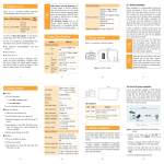
Functional description of CMP-600T
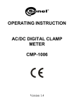
Measuring terminals and components of the measuring function selection
① Clamps
② Clamp contact point
③ Protective ring (protection barrier)
④ Lever for clamp opening
⑤ Rotary switch
Function selection:
•
OFF – meter switched off
– AC measurement
•
– DC measurement
•
•
– AC/DC voltage measurement
•
- resistance measurement, diode check, continuity test
•
Hz – frequency measurement
⑥ HOLD button
Freezing the measurement results on the display.
⑦ ⑧ Rel./Sel. button
•
for - relative measurement
•
for setting "0"
•
for
selecting between AC/DC
•
for
selecting between resistance measurement / diode test / circuit continuity test
⑨ TX ON button
Turning the wireless transmission ON.
⑩ FUNCTION button
Transmission configuration.
⑪ SET button
Setting the transmission parameters.
⑫ Nameplate
31
⑬ COM input port
Measurement input for all measurement functions except current measurement (connected to the
ground of the meter).
⑭ Input port
Measurement input for AC/DC DC voltages, frequency, resistance and diodes.
⑮ Liquid Crystal Display (LCD)
3.2
Liquid Crystal Display (LCD)
Symbols and units
Description
Setting ID code for transmission (channel no. from 1 to 6).
Transmission mode ON.
The choice of transmission time: 2, 10, 30, 60 or 120 seconds.
DC measurement.
AC measurement.
Negative polarity.
Auto-ranging
Circuit continuity test.
Diode test.
HOLD mode (result by) enabled.
Measurement in relative mode or setting the "zero" point.
Low battery level.
Frequency measurement unit
Resistance measurement unit.
Voltage measurement unit.
Current measurement unit.
Displaying measurement results.
3.3
Leads
The manufacturer guarantees the correctness of read-outs only when original test leads are used.
WARNING:
Connecting wrong or damaged leads may cause electric
shock (dangerous voltage) or improper measurement.
32
4
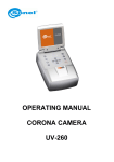
4.1
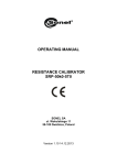
Functional description of CMP-600R
Components of the measuring function selection
① Nameplate
② Liquid Crystal Display (LCD)
③ POWER button
Switching power ON/OFF (after 3 s).
④ READ button
Readout of saved maximum and minimum values.
Additional function (▲): changing digits while setting the clock and limit values.
⑤ HOLD/MAX-H function
Freezing the measurement results on the display/ freezing maximum result.
Additional function (SET): to work with FUNCTION button to set the transmission time and to work with CHANNEL button, to set ID code that enables switching on/off the transmission function.
⑥ MAX./MIN button.
Saving maximum or minimum measurement result.
Additional function (▲): switching to other digits while setting the clock and limit values.
⑦ ALARM button
Setting the limit (activating the measurement with a limit).
⑧ CLOCK SET button
Setting the clock.
⑨ SEARCH button
Manual search for the signal.
Additional function (BEEP CANCEL): deactivates the alarm.
Additional function (FUNCTION): setting the transmission time.
⑩ CHANNEL button
Switching channels.
⑪ USB port (in devices with USB function)
⑫ PWR terminal
External DC power supply 3V/10mA.
33
4.2
Liquid Crystal Display (LCD)
Symbols and units
Description
Setting ID code for transmission (channel no. from 1 to 6).
The symbol flashes when receiving a signal from the transmitter.
Saved maximum and minimum values.
Readout of saved maximum and minimum values.
In alarm mode when the result is < or > from preset limits.
Auxiliary field: clock in 24-hour mode.
DC measurement.
AC measurement.
Negative polarity.
Diode test.
Relative mode of the measurement.
Circuit continuity test.
Main field: measurement result.
Low battery level of receiver.
Low battery level of transmitter.
Readout of saved maximum and minimum values.
HOLD mode enabled - measurement result frozen on the display.
PC connection (this symbol appears when the meter has USB
function).
Alarm mode: the symbol flashes and alarm is activated when the
measurement result reaches the pre-set limit value.
Transmission time: 2, 10, 30, 60, 120 s
No signal from the transmitter.
Frequency measurement unit
Resistance measurement unit.
Voltage measurement unit.
Current measurement unit.
34
5
Measurements
The content of this chapter should be thoroughly read and understood since it describes methods
of measurements and basic principles of interpreting measurement results.
5.1
Current measurement
WARNING:
Do not conduct measurements on a circuit where the voltage exceeds 600V AC/DC. Do not
conduct measurements on circuits with unknown potential.
WARNING:
Do not start the measurement when the battery compartment is open.
WARNING:
Do not start the measurement with test leads connected to the meter.
Note:
During current measurements, make sure that the meter clamps are fully tightened. Otherwise, the meter will not be able to make accurate measurements. The most accurate measurements are available when tested wire/conductor is placed centrally between meter
clamps.
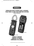
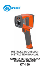
5.1.1 AC measurement
To perform AC measurement:
•
Set the rotary switch at ,
•
open clamps of the meter and close them around a single wire (figure below),
•
read the measurement result on the display,
•
after completing the measurement turn off the meter.
5.1.2 DC measurement
To perform DC measurement:
•
Set the rotary switch at ,
•
press REL button to set 'zero' (auto-ranging will be disabled and the measurement range will be
set after pressing REL),
•
open clamps of the meter and close them around a single wire,
•
after readouts stabilize - read the measurement result on the display,
•
after completing the measurement turn off the meter.
35
Notes:
- If the minor readouts before the measurement are not taken into account, it is not necessary to press
REL button in order to set the "zero" point - then the measurement will be conducted in auto-ranging
mode.
- When symbol
appears, it means that the measured current direction is opposite to the polarization indicated on the clamp.
5.2
DC voltage measurement
WARNING:
Do not conduct measurements on a circuit where the voltage exceeds 600V AC with regard to
the ground. Do not conduct measurements of voltages exceeding 600V AC/DC. The potential
of the COM input port with regard to the ground must not exceed 600V AC/DC.
WARNING:
Do not start the measurement when the battery compartment is open.
To perform DC voltage measurement:
•
Set the rotary switch at
,
terminal , and black test lead to COM terminal ,
•
connect red test lead to
•
contact the blades of test probes to the points of measurement; in DC measurements red probe
should be applied to the point of higher potential,
•
read the measurement result on the display,
•
after completing the measurements remove test leads from the terminals and turn off the meter.
Notes:
- When symbol
of the meter.
5.3
appears, it means that the polarization of the object is opposite to the polarization
Measurement of alternating voltage
WARNING:
Do not conduct measurements on a circuit where the voltage exceeds 600V AC with regard to
the ground. Do not conduct measurements of voltages exceeding 600V AC/DC. The potential
of the COM input port with regard to the ground must not exceed 600V AC/DC.
WARNING:
Do not start the measurement when the battery compartment is open.
To perform AC voltage measurement:
•
Set the rotary switch at
,
•
press REL./SEL. button and the following symbol will be displayed:
,
•
connect red test lead to
terminal , and black test lead to COM terminal ,
•
contact the blades of test probes to the points of measurement,
•
read the measurement result on the display,
•
after completing the measurements remove test leads from the terminals and turn off the meter.
5.4
Measurement of resistance
WARNING:
Do not conduct measurements on the circuit under the voltage.
WARNING:
Do not start the measurement when the battery compartment is open.
36
To perform the resistance measurement:
,
•
Set the rotary switch at
•
connect red test lead to
terminal , and black test lead to COM terminal ,
•
contact the blades of test probes to the points of measurement,
•
read the measurement result on the display,
•
after completing the measurements remove test leads from the terminals and turn off the meter.
Notes:
- Do not touch the metal probe with your hand to avoid measurement errors.
5.5
Diode test
WARNING:
Do not conduct measurements on the circuit under the voltage.
WARNING:
Do not start the measurement when the battery compartment is open.
To perform the diode test:
•
Set the rotary switch at
,
•
press REL./SEL. button and the following symbol will be displayed: ,
terminal , and black test lead to COM terminal ,
•
connect red test lead to
•
contact the blades of test probes to the diode: red test lead should contact the anode and the
black should contact cathode,
•
read the measurement result on the display: forward voltage of the diode is displayed, which for
a typical silicon diode is approx. 0.7 V and for germanium diodes is approx. 0.3 V; when the diode is polarized in backward direction or the circuit is broken, the display will indicate OL; when
the diode is shorted, then the display will indicate 0000 or other value,
•
after completing the measurements remove test leads from the terminals and turn off the meter.
5.6
Circuit continuity test.
WARNING:
Do not conduct measurements on the circuit under the voltage.
WARNING:
Do not start the measurement when the battery compartment is open.
To perform the continuity test:
,
•
Set the rotary switch at
•
pressREL./SEL. button twice and the following symbol will be displayed
,
•
connect red test lead to
terminal , and black test lead to COM terminal ,
•
contact the blades of test probes to the points of measurement,
•
read the measurement result on the display; beep will be activated when resistance values are
below approx. 100Ω,
•
after completing the measurements remove test leads from the terminals and turn off the meter.
5.7
Frequency measurement
To perform frequency measurement:
•
Set the rotary switch at Hz,
•
connect red test lead to
terminal , and black test lead to COM terminal ,
•
contact the blades of test probes to the points of measurement,
•
read the measurement result on the display,
•
after completing the measurements remove test leads from the terminals and turn off the meter.
37
6
Special features of the transmitter
6.1
HOLD function
By pressing HOLD button, you will freeze currently displayed measurement values and the dis. By pressing button again you will return to normal display of currently measured
play shows
values.
This function is available only for current and voltage measurements.
6.2
Differential (relative) mode of measurement
In order to activate the differential mode of measurement press REL./SEL. button (the following
). Then the result is displayed as the difference between the reference
symbol will be displayed
value and the current read-out (measured at the moment of pressing the button). For example: if the
reference value is 20A and the current reading is 12.5A, then the display will show the result of -7.5 A.
If the new reading is identical to the reference value, then the display will show zero. Pressing
REL./SEL. button again will close the differential measurement mode.
This function works only for AC measurements , whereas for DC measurements it enables the
user to set zero.
Notes:
- In the differential measurement mode, the measurement range is fixed, depending on the reference
value (message AUTO RANGE disappears). To restore the autorange function, turn the meter OFF
and back ON, when set on the desired function.
- The above remark also applies to DC measurements. In this case the reference value is "0".
6.3
Transmission mode
To activate the transmission mode press TX ON button and the following symbol
played. The transmission mode ends, when the button is pressed again and
will be dis-
symbol disappears. (In
mode, the display is refreshed approx. once per second.)
6.4
Transmission settings
To set the transmission time, press FUNCTION button for 2 s., the following symbol appears TS.
Another short press of the button will switch to ID setting - which is the number of the transmission
channel (1 .. 6). Setting the transmission time or ID is performed with SET button.
Pressing FUNCTION button for 2 s. will bring the meter back to the measurement mode.
Notes:
- When using one transmitter for sending data to one receiver, the transmission time of both devices
must be the same to ensure correct data transfer. Also the ID code of the two devices must be the
same.
7
7.1
Special features of the receiver
HOLD and MAX-HOLD functions
By pressing HOLD/MAX-H button, you will freeze currently displayed measurement values and
the display shows HOLD. By pressing button again you will return to normal display of currently measured values.
By pressing HOLD/MAX-H button for 2 s. you will display maximum value of the measurement
result on the display, which will show MAX HOLD. By shortly pressing button again you will return to
normal display of currently measured values.
This function is available only for current and voltage measurements.
38
7.2
Saving and displaying the maximum and minimum value
Press MAX/MIN button to
enter the mode of saving
maximum and minimum
values.
The meter returns to MEMO
MAX/MIN mode when for 10
s. READ button is not pressed.
Press READ button to
read the saved maximum
value.
Press READ button to read the saved minimum
value.
Press MAX/MIN button to
cancel MAX/MIN mode
and return to the measurement mode.
Notes:
- After returning to the measurement mode saved max./min. value are stored in memory.
- Pressing READ button in the measurement mode will show stored values.
7.3
Measurement mode with alarm
The meter allows user to set the maximum value (upper limit) or minimum value (lower limit).
When these values are exceeded the meter will beep (alarm) for 2 minutes. The beep may be deactivated by pressing SEARCH/BEEP CANCEL, button, providing that the current measurement result is
between minimum and maximum value.
To enable the measurement mode with alarm, press ALARM button - the following symbol is displayed
. Pressing the button again will disable this function.
In order to set a limit press ALARM and then SEARCH.
The meter is in limit setting mode.
Press ► button.
Press ▲ button to select the upper (HI) or lower (LO) limit .
Press ► button.
39
Press ▲ button to select the
symbol "+" or "-"
Press ► button.
Press ▲ to set the value of the
first digit. Using ▲ and ► buttons set the values of remaining digits.
Press ► button.
Press ▲ button to move the
position of the decimal point.
Press ► button.
Press ▲ button to
choose a unit: V, mV or A.
Press ALARM button- setting the limit is completed. Automatic return to the measurement mode takes
place after 10 sec. of meter inactivity on each stage
7.4
Reception Settings
To switch to activation of channels press SEARCH (FUNCTION) button for 2 sec. Another short
press of the button will switch the meter to transmission time setting. Press HOLD/MAX-H(SET) button to activate ("ON") or deactivate ("OFF") individual channels, press CHANNEL to change channel
number (ID). Transmission time is set with HOLD/MAX-H(SET) button
Pressing SEARCH(FUNCTION) button again for 2s. will bring the meter back to the measurement
mode.
Notes:
- When using one transmitter for sending data to one receiver, the transmission time of both devices
must be the same to ensure correct data transfer. Also the ID code of the two devices must be the
same.
7.5
Setting the clock.
To set the clock, press CLOCK SET button and immediately press ► or ▲ (the meter after 2 s.
automatically returns to the measurement mode). Use ► to switch between set digits and use ▲ to
set their values.
The meter automatically returns to the measurement mode after 10 s. or after pressing CLOCK
SET button.
40
7.6
Operation with multiple transmitters
When using multiple transmitters which transmit data to one receiver, power consumption is higher
due to the continuous data transmission. When using one transmitter, set the remaining 5 ID codes to
"OFF", in order to reduce power consumption.
When using multiple transmitters which transmit data to one receiver, transmission time may be
selected and set for each channel.
Notes:
- In the measurement mode you can switch active ("on") channels with CHANNEL button.
7.7
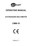
Operation with PC
Install "Wireless clamp meter" software on your computer and USB driver included on the enclosed CD. The software works with Windows XP, Vista and 7. Connect CMP-600R receiver to PC via
USB cable. After starting the program will show its main window, and the description of individual tabs
and icons below:
File
Open file
Save data or graph
Print data or graph
Exit the program
Configuration
Automatic scan of COM
port or manual selection
Setting the upper (Hi) or
lower (Low) limit and
Unit
Channel:
The user may change
the name and description of channels 1 .. 6
Default settings
Timeline scale
Setting parameters
for calculating the
charges for electricity: voltage (V),
cosφ (P.F.) and
the unit price
41
Edition
Clears the current data records and charts
View
1 - Monitor: current data
2 - Table: data
presented in a table
3 - Graph: data presented
on a graph
4 - Estimated electricity
costs
2
1
3
4
1
2 3
4
Screen
Transmission time
File Name
Transmitted unit
Number of receiving channels
Displayed channel
Channel description (serial
number, location)
Alarm limits
Average value until present
Maximum value until present
Minimum value until present
Present value
Table
Graph: current page
previous page
42
next page
Estimated electricity costs
Notes:
- The above screen is not displayed when the transmission starts. Set the network nominal
voltage, cosφ and the unit price of electricity in the Setup tab and select "Estimate Electricity Charge" in the View tab to begin calculations of electricity costs.
Records
1
2
3
4
1
2
3
1 - Connect: CMP-600 to
PC
2 - Start: starts data
collection
3 - Pause: pause in data
collection
4 - Stop: end of data collection
4
Notes:
- During the pause the file cannot be saved.
Option
Monitor
Graph
Selecting the background colour and font for displaying measured values on the screen.
Selecting the background colour, chart type and
entering the name of the chart.
43
Table
Selecting the background colour and type of grid
in the table.
Window
Arranging windows
Help
Operating manual for the meter
Operating manual
About the software
8
Warnings and information displayed by the meter
Displayed
symbol
Cause
Measuring range is
exceeded.
Disconnect the test leads from the measured
object
displayed by
the transmitter
Battery discharged
Replace the battery
displayed by
the receiver
Receiver battery discharged
Replace the battery
displayed by
the receiver
Transmitter battery
discharged
Replace the battery
HOLD function enabled
Differential (relative)
mode of measurement is enabled
44
Action
9
Replacing the battery
Both the transmitter and the receiver of CMP-600 are powered by two 1.5V AA batteries. We recommend using LR6 alkaline batteries .
WARNING:
If the test leads are left in the terminals during replacement
of the batteries, there is a risk of electric shock with a dangerous voltage.
To replace the battery:
6. Remove the test leads from the measurement terminals of the transmitter, turn off the transmitter
(receiver).
7. Remove the screw that secures the battery cover (the bottom of the compartment),
8. Remove the battery cover.
9. Remove discharged batteries and insert new observing proper polarity.
10. Replace the removed cover and tighten screws.
10 Cleaning and maintenance
The casing of the meter may be cleaned with a soft, damp cloth using all-purpose detergents. Do
not use any solvents or cleaning agents which might scratch the casing (powders, pastes, etc.).
The electronic system of the meter does not require maintenance.
11 Storage
•
•
•
During the storage of the meter, the following recommendations must be observed:
disconnect the leads from the transmitter,
make sure that the transmitter, receiver and accessories are dry,
when the meter is to be stored for prolonged period of time, batteries must be removed from the
device.
12 Dismantling and Disposal
Used electrical and electronic equipment should be collected selectively, i.e. it must not be placed
with another kinds of waste.
Used electronic equipment should be sent to a collection point in accordance with the Used Electrical and Electronic Equipment Act.
Before the equipment is sent to a collection point, do not dismantle any elements.
Observe the local regulations concerning disposal of packages, worn-out batteries and accumulators.
13 Annexes
13.1 Technical specifications
•
"d.v." used in the specification of measurement uncertainty means "displayed value"
True RMS measurement for AC (50...500Hz)
Display range
Resolution
Measurement uncertainty (basic)
400A
0.1A
± (1.8% d.v. + 10 digits)
600A
1A
± (1% d.v. + 5 digits)
45
DC measurement
Display range
Resolution
Measurement uncertainty (basic)
400A
0.1A
± (1.8% d.v. + 10 digits)
600A
1A
± (1% d.v. + 5 digits)
True RMS voltage measurement for AC (50...500Hz)
Display range
Measurement uncertainty (baResolution
sic)
4V
0.001V
40V
0.01V
400V
0.1V
600V
1V
DC voltage measurement
Display range
Resolution
400mV
0.1mV
4V
0.001V
40V
0.01V
400V
0.1V
600V
1V
Input Impedance
11MΩ
± (1.5% d.v. + 10 digits)
10MΩ
± (1.5% d.v. + 5 digits)
Measurement uncertainty (basic)
Input Impedance
± (0.75% d.v. + 3 digits)
≥100MΩ
11MΩ
± (1% d.v. + 3 digits)
10MΩ
Measurement of resistance
Display range
•
400Ω
4kΩ
40kΩ
400kΩ
4MΩ
40MΩ
opening voltage -approx. 0.4 V
Resolution
0.1Ω
0,001kΩ
0.01kΩ
0.1kΩ
0.001MΩ
0.01MΩ
Measurement uncertainty
(basic)
± (1% d.v. + 5 digits)
± (3% d.v. + 5 digits)
± (5% d.v. + 5 digits)
Continuity test
Display range
•
Resolution
400Ω
0.1Ω
beep for resistance values below approx. 100Ω
Measurement uncertainty
(basic)
Not specified
Diode test
Display range
•
46
1.000V
opening voltage: approx. 1.5 V
Resolution
0.001V
Measurement uncertainty
(basic)
± (10% d.v. + 5 digits)
Frequency measurement
Range
•
•
Resolution
5.000Hz
0.001Hz
50.00Hz
0.01Hz
500.0Hz
0.1Hz
5.000kHz
0.001kHz
50.00kHz
0.01kHz
100.0kHz
0.1kHz
Uncertainty for the sinusoidal signal
Sensitivity: 5V rms for f = 5Hz...100kHz
Measurement uncertainty
(basic)
± (0.7% d.v. + 5 digits)
NOTE: Presented values of uncertainty are increased by an additional value of 0.1 x specified uncertainty for each 1°C change when the ambient tempera ture is below 18°C or above 28°C.
Other technical specifications
a)
b)
c)
d)
e)
f)
g)
h)
i)
j)
k)
l)
m)
n)
o)
p)
q)
r)
measurement category according to PN-EN 61010-1:2004 ............................................. III 600V
protection class of enclosure acc. to PN-EN 60529 .............................................................. IP40
power supply for transmitter and receiver .................................................two LR6 batteries 1,5V
time of continuous operation................ 300h without transmission, 100h with transmission (t=2s)
maximum cable diameter.......................................................................Ø30mm or rail 35x10mm
transmitter dimensions..................................................................................... 220 x 64 x 35 mm
receiver dimensions......................................................................................... 179 x 72 x 32 mm
weight of the transmitter without batteries................................................................ approx. 251g
weight of the receiver without batteries .................................................................... approx. 177g
reference temperature ..................................................................+23 ± 2°C, rel. humidity < 80%
operating temperature .................................................................-10..+50°C, rel. humidity < 80%
storage temperature .................................................................. –20..+60°C, rel. humidity < 70%
sampling frequency .................... 3x/s without data transmission and 1x/s with data transmission
transmission frequency.............................................................................................. 433.62MHz
polarization .............................................................automatic, indicating negative polarization (-)
display ..................................................................................................................... LCD, 4 digits
compliance with the requirements of the standards ............. EN 61010-1:2004, EN 61010-2-032
quality standard .............................................................................................................ISO 9001
13.2 Standard equipment
Standard set of equipment supplied by the manufacturer includes:
• CMP-600 meter – WMPLCMP600
• test leads (2 pcs) – WAPRZCMP1
• AA batteries 1.5V (4 pieces)
• a case for the meter and accessories
• CD
• Operating manual
13.3 Optional accessories
•
calibration certificate– LSWPLCMP600
47
13.4 Service
The provider of warranty and post-warranty services is:
SONEL S.A.
ul. Wokulskiego 11
58-100 Świdnica
Poland
tel. +48 74 858 38 60
fax +48 74 858 38 09
E-mail: [email protected]
Web page: www.sonel.pl
Note:
Service repairs must be performed solely by SONEL S.A.
13.5 Laboratory services
Measurement Laboratory of SONEL SA offers tests and certification of the following instruments in the
scope of their electrical/non-electrical features:
-
-
infrared cameras,
pyrometers,
meters for conducting the following electrical protective measurements: insulation resistance, earth resistance and impedance, short-circuit loops, RCD parameters and multi-functional meters that perform the
above functions,
electrical safety meters,
power quality analyzers,
meters for measuring low resistance values,
voltage meters, current meters (including clamp meters), resistance meters and multimeters,
light meters.
A calibration certificate is a document confirming compliance of parameters declared by the manufacturer of tested device with national standards, specifying the measurement uncertainty
In accordance with PN-ISO 10012-1, Annex A – "Requirements for assuring quality of measurement equipment. The system for approving metrological measuring equipment" –SONEL S.A. recommends for its instruments to be periodically tested, observing -- 13-month intervals.
Note:
In case of instruments used for tests related to the protection against electric shock, the person - performing measurements should have complete confidence in the efficiency of used apparatus. Measurements carried out with
malfunctioning meter may cause wrong assessment of
tested equipment in terms of its protection features
The product was made in Taiwan at the order of SONEL S.A.
48