1
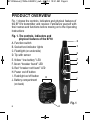
BF10-Manual_FINAL4-082012_awb 8/20/12 10:31 AM Page 1
AC CIRCUIT BREAKER
FINDER
USER’S MANUAL
BF10
Please read this manual carefully and thoroughly before using this product.
BF10-Manual_FINAL4-082012_awb 8/20/12 10:31 AM Page 2
TABLE OF CONTENTS
Introduction . . . . . . . . . . . . . . . . . . . . . . . . . . . . 3 – 4
Key Features . . . . . . . . . . . . . . . . . . . . . . . . . . . 4 – 5
Safety Instructions . . . . . . . . . . . . . . . . . . . . . . . . . . 5
What’s in the Blister Pack . . . . . . . . . . . . . . . . . . . . 5
Product Overview . . . . . . . . . . . . . . . . . . . . . . . . . . . 6
Operating Instructions . . . . . . . . . . . . . . . . . . . . 7 – 8
Specifications . . . . . . . . . . . . . . . . . . . . . . . . . . . . . . 9
Changing the Battery . . . . . . . . . . . . . . . . . . . . . . . 10
Warranty Information . . . . . . . . . . . . . . . . . . . 10 – 11
Return for Repair Policy . . . . . . . . . . . . . . . . . 11 – 12
2
BF10-Manual_FINAL4-082012_awb 8/20/12 10:31 AM Page 3
INTRODUCTION
Thank you for purchasing General Tools & Instruments’
(General’s) BF10 AC Circuit Breaker Finder. Please read this
manual carefully and thoroughly before using the product.
The BF10 can perform two functions:
1. Automatically identify the circuit breaker or fuse
associated with any 110V outlet without tripping the
breaker or blowing the fuse
2. Identify five common receptacle wiring faults
The AC Circuit Breaker Finder has two components—an ACpowered transmitter and a battery-powered receiver. When
the transmitter is plugged into an AC outlet, it powers on and
sends a signal down the branch circuit all the way to the
circuit breaker panel. If the tip of the battery-powered
receiver is then used to “scan” all of the panel’s breakers (in
other words, touch each one in turn), a sensor in the tip will
light a green LED on the front of the receiver each time it
detects a signal. If no signal is detected, a red LED will light.
A first scan will cause the green LED to light several times if
the transmitter’s signal has leaked onto adjacent branch
circuits. On a rare occasion a second scan may be needed.
During each scan, the BF10 uses a patented circuit that
automatically adjusts the sensitivity of the sensor to rule out
weaker signals representing “false positives.”
3
BF10-Manual_FINAL4-082012_awb 8/20/12 10:31 AM Page 4
The plug-in transmitter also doubles as a socket tester. By
measuring leakage currents, it can identify five common
outlet wiring faults: missing earth (ground), missing neutral,
live and earth reversed, live and neutral reversed, and open
circuit. The type of fault is indicated by a unique pattern of
colored LEDs on the front of the transmitter as well as the
pulsed tone that it emits.
The BF10 is NOT a comprehensive diagnostic instrument:
• It cannot test the ground fault circuit interruption function of
GFCI receptacles.
• It cannot measure the quality of earth (ground) connections,
detect two hot wires or more than one fault in a circuit, or
detect reversed grounded and grounding conductors.
The BF10 is a simple instrument for detecting common
improper wiring of GFCI and non-GFCI outlets. All detected
problems should be referred to a qualified electrician.
If you need a comprehensive diagnostic instrument, General
recommends its CA10 Circuit Analyzer. For details, visit
www.generaltools.com and enter “CA10” in the SEARCH box.
KEY FEATURES
• Automatically locates the breaker or fuse associated with any
110V outlet without tripping the breaker or blowing the fuse
• Also identifies five common outlet wiring faults
4
BF10-Manual_FINAL4-082012_awb 8/20/12 10:31 AM Page 5
• CAT II 600V, CAT III 300V, double-insulated
• Built-in flashlight for use in dark areas
• Compatible with GFCI receptacles
• Audible tone and visual (LED) indications
• Low battery warning
• Complies with safety standard IEC 61010-1
• Includes “9V” receiver battery
SAFETY INSTRUCTIONS
!
!
WARNING!
Exercise caution when working around
circuit breaker panels.
Do not use this instrument on circuits with
voltages higher than 110V.
WHAT’S IN THE BLISTER PACK
The BF10’s transmitter and receiver come in a blister pack
along with a “9V” battery (pre-installed in the receiver) and
this user’s manual.
5
BF10-Manual_FINAL4-082012_awb 8/20/12 10:31 AM Page 6
PRODUCT OVERVIEW
Fig. 1 shows the controls, indicators and physical features of
the BF10’s transmitter and receiver. Familiarize yourself with
their names and functions before moving on to the Operating
Instructions
Fig. 1. The controls, indicators and
physical features of the BF10
D
A. Function switch
C
B. Socket test indicator lights
C. Flashlight (on underside)
E
D. Tip with sensor
F
E. Yellow “low battery” LED
G
F. Green “breaker found” LED
G. Red “breaker not found” LED
H
H. Power on/off button
I. Flashlight on/off button
B
I
J. Battery compartment
(on back)
J
Fig. 1
6
A
BF10-Manual_FINAL4-082012_awb 8/20/12 10:31 AM Page 7
OPERATING INSTRUCTIONS
Before plugging the BF10 transmitter into either kind of
branch circuit receptacle (GFCI or non-GFCI), unplug all
appliances and equipment connected to that circuit. If you're
not sure whether an appliance or a piece of equipment is
powered by the circuit to be tested, unplug it to err on the
side of caution. Then plug in the transmitter.
To check a 110V GFCI or non-GFCI outlet for wiring faults,
slide the function switch on the transmitter (Fig. 1, Callout A)
to the right (the Socket Test position).
• If the outlet has no wiring faults, the two green LEDs in
the top row of socket test indicator lights will illuminate
(turn on) and a continuous tone will be heard.
• If the outlet has an open circuit or is not powered, no LEDs
will illuminate and no tone will be heard (because the
transmitter will remain unpowered).
• If the outlet has any of four common wiring faults (missing
earth (ground), missing neutral, live and earth reversed, and
live and neutral reversed), a unique pattern of one or more
green LEDs, or green and red LEDs, particular to that fault
will be displayed and a pulsed tone will be heard. Labels
to the right of the LEDs indicate which fault has been
detected.
7
BF10-Manual_FINAL4-082012_awb 8/20/12 10:31 AM Page 8
To identify the breaker or fuse associated with the branch
circuit the transmitter is plugged into:
1. Slide the function switch on the transmitter to the left (the
Breaker Find position).
2. Go to the circuit breaker panel and begin scanning
breakers by touching the tip of the receiver to each breaker
in turn. If the panel is in a dark area, turn on the built-in
flashlight (Fig. 1, Callout C) by pressing the
button
(Callout I). Touching breakers will cause the red LED on the
receiver (Fig. 1, Callout G) to light but at least one breaker
will cause the green LED on the receiver (Fig. 1, Callout F)
to light. If only one breaker causes the green LED to light,
that breaker is the one associated with the outlet that the
transmitter is plugged into.
3. If more than one breaker caused the green LED to light,
scan all breakers in the panel again. If doing so causes the
green LED to light just once, the breaker that “tested
positive” is the breaker associated with the outlet that the
transmitter is plugged into.
4. If the second scan lights the green LED more than once,
scan all the breakers a third time. A third scan will always
light the green LED on the receiver just once. The breaker
that tested positive is the one associated with the outlet
that the transmitter is plugged into.
8
BF10-Manual_FINAL4-082012_awb 8/20/12 10:31 AM Page 9
SPECIFICATIONS
Socket Wiring Indications
Operating Temperature
Dimensions
Weight
Power Source
Certifications
Correct wiring
Missing earth (ground)
Missing neutral
Live & earth reversed
Live & neutral reversed
Open circuit
32° to 122°F (0° to 50°C)
Transmitter: 2.8 x 2.5 x 2.3 in.
(71 x 64 x 58mm)
Receiver: 7.4 x 1.8 x 1.5 in.
(188 x 46 x 38mm)
Transmitter: 2.1 oz. (60g)
Receiver: 4.3 oz. (122g)
1 “9V” battery for receiver
(included)
CAT II 600V, CAT III 300V
CE
RoHS
Safety standard IEC 61010-1
9
BF10-Manual_FINAL4-082012_awb 8/20/12 10:31 AM Page 10
CHANGING THE BATTERY
When the yellow LED on the receiver (Fig. 1, Callout E)
illuminates, it’s time to change the battery. The battery
compartment (Callout J) is accessible from the back of the
receiver.
To replace the battery:
1. Open the compartment by loosening and removing the
single Phillips-head screw securing the compartment cover
to the bottom of the receiver. Remove the screw and cover
and set them aside.
2. Remove the old battery and plug a fresh “9V” battery into
the wired socket inside the compartment. The terminals of
the battery and the socket mate in only one way, with the
smaller male terminal plugging into the larger female
terminal.
3. Replace the battery compartment cover and secure it to
the back of the receiver with the Philips-head screw.
WARRANTY INFORMATION
General Tools & Instruments’ (General’s) BF10 AC Circuit
Breaker Finder is warranted to the original purchaser to be
free from defects in material and workmanship for a period of
one year. Subject to certain restrictions, General will repair or
10
BF10-Manual_FINAL4-082012_awb 8/20/12 10:31 AM Page 11
replace this instrument if, after examination, the company
determines it to be defective in material or workmanship.
This warranty does not apply to damages that General
determines to be from an attempted repair by non-authorized
personnel or misuse, alterations, normal wear and tear, or
accidental damage. The defective unit must be returned to
General Tools & Instruments or to a General-authorized
service center, freight prepaid and insured.
Acceptance of the exclusive repair and replacement remedies
described herein is a condition of the contract for purchase of
this product. In no event shall General be liable for any
incidental, special, consequential or punitive damages, or for
any cost, attorneys’ fees, expenses, or losses alleged to be a
consequence of damage due to failure of, or defect in any
product including, but not limited to, any claims for loss of
profits.
RETURN FOR REPAIR POLICY
Every effort has been made to provide you with a reliable
product of superior quality. However, in the event your
instrument requires repair, please contact our Customer
Service to obtain an RGA (Return Goods Authorization)
number before forwarding the unit via prepaid freight to the
attention of our Service Center at this address:
11
BF10-Manual_FINAL4-082012_awb 8/20/12 10:31 AM Page 12
General Tools & Instruments
80 White Street New York, NY 10013 212-431-6100
Remember to include a copy of your proof of purchase, your
return address, and your phone number and/or e-mail
address.
GENERAL TOOLS & INSTRUMENTS
80 White Street
New York, NY 10013-3567
PHONE (212) 431-6100
FAX (212) 431-6499
TOLL FREE (800) 697-8665
e-mail: [email protected]
www.generaltools.com
BF10 User’s Manual
Specifications subject to change without notice
©2012 GENERAL TOOLS & INSTRUMENTS
NOTICE - WE ARE NOT RESPONSIBLE FOR TYPOGRAPHICAL ERRORS.
BF10 8/18/12