1
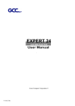
Apricus Sentinel-Pro
Multi-Function Solar Controller
Installation & User Manual
Edition 1.3 - June 2007
Please read this manual carefully to ensure safe and reliable operation of the controller.
Apricus Sentinel-Pro Solar Controller
Page 2
Installation & User Manual
Contents
Page
Introduction
Technical Data
Safety Precautions
3
4
5
1. Installation
1.1. Mounting
1.2. Electrical Connection
1.3. Sensor Connection
1.4. Communication Port
6
6
7
7
2. LCD Display
8
3. Function Overview
3.1. Function Table
3.2. Function Rules
3.3. Detailed Function Explanation
9
9
9
4. Error Reporting
11
5. Settings
5.1. Control Buttons
5.2. Setting Time
5.3. Programming Relay Times
5.4. Controlling Relays (ON/OFF/AUTO)
5.5. Setting Temperature Ranges
5.6. Turning Functions OFF
5.7. Changing Temperature Format (oC or oF)
5.8. System Default Settings
12
12
12
12
13
13
13
13
6. System Diagrams
6.1. Basics Solar Collector System
6.2. Solar Collector System with Heat Boosting
6.3. Solar Collector System with Heat Extraction
6.4. Solar Collector System with Heat Boosting & Extraction
6.5. Twin Tank Solar Collector System (forced circulation)
6.7. Heat Boosting System
6.8. Heat Extraction System
14
14
15
15
16
16
17
7. Troubleshooting
7.1. Sensor Failures (Errors E3, E4 & E5)
7.2. Inaccurate Sensor Readings
7.3. Miscellaneous Problems
18
18
18
8. Maintenance
19
9. Warranty
19
10. Disclaimer
19
11. Installation Record Form
20
© 2007 Apricus Solar Co. Ltd
No responsibility will be accepted for any mistakes or technical changes
AS-1.2.10.1 Rev: 16/7/07
402 Building 8 East, Pukou New & High Tech Development Zone, Nanjing, China, 210061
Ph: +86 25 58649133 eFax: +1 206 338 4189
Web: www.apricus.com
Email: [email protected]
Apricus Sentinel-Pro Solar Controller
Page 3
Installation & User Manual
Introduction
The Sentinel-Pro solar controller is a multi-function device used to monitor and control thermal solar
systems. With comprehensive control over temperature ranges and the operation of each relay, the
Sentinel-Pro is suitable for both domestic and commercial applications. An LCD display provides
clear feedback on the status of the system.
Key Features
✓ Clear LCD display of all temperatures, relay operation and errors
✓ Adjustable temperature ranges for all functions
✓ ON/OFF/AUTO control of each relay
✓ Daily time control of each relay
✓ Auto-recover after power cutout, full memory of system settings
✓ Easy to mount casing with punch out panels for conduit entry
✓ High accuracy NTC 100K temperature sensors
© 2007 Apricus Solar Co. Ltd
No responsibility will be accepted for any mistakes or technical changes
AS-1.2.10.1 Rev: 16/7/07
402 Building 8 East, Pukou New & High Tech Development Zone, Nanjing, China, 210061
Ph: +86 25 58649133 eFax: +1 206 338 4189
Web: www.apricus.com
Email: [email protected]
Apricus Sentinel-Pro Solar Controller
Page 4
Installation & User Manual
Technical Data
Inputs: 3 temperature sensors (NTC 100K)
➙ Controller supplied standard with:
- 2 x 2m / 78" low temp sensor (Max 1104 oC / 230oF)
- 1 x 2m / 78" high temp sensor (Max 200 oC / 395 oF)
Outputs: 3 relays, 4A each; Total max 6A
Power Supply: 110-240V (AC), 50-60Hz
Power Consumption: 4 Watts
Fuse Rating: 8A
Error Reporting: LCD display of each error & 10 sec audible alarm
Casing: ABS Plastic
Display: Liquid Crystal Display (LCD)
➙ 24 hour format time display
➙ Individual display of all errors
➙ Individual display of all three sensor temperatures (oC or oF)
➙ Individual display of relay status including time setting
➙ Power status
Operation: 7 push buttons
➙ Power, Time, Relay, Function, Up, Down, Set
Mounting: 2 x rear slots for wall mounting on screw head
Dimensions & Weight:
➙ LxWxH: 200x210x39mm / 8.6x8.2x1.5”
➙ Gross Weight: 600g / 1.32lb (not includind sensors)
Environmental Conditions: 0-40oC / 32-104oF, Indoor use only
Communication Port: For connection of optional data reading equipment
Electrostatic discharge can cause
damage of electronic components
© 2007 Apricus Solar Co. Ltd
Warning! Parts are high energy
voltage energized.
No responsibility will be accepted for any mistakes or technical changes
AS-1.2.10.1 Rev: 16/7/07
402 Building 8 East, Pukou New & High Tech Development Zone, Nanjing, China, 210061
Ph: +86 25 58649133 eFax: +1 206 338 4189
Web: www.apricus.com
Email: [email protected]
Apricus Sentinel-Pro Solar Controller
Page 5
Installation & User Manual
Safety Precautions
Electrostatic Discharge
Care should be taken to avoid exposure of the controller to electrostatic discharges, as this
could damage circuity components.
High Voltage
The controller is high voltage energized and therefore MUST have power supply disconnected
when the bottom cover is opened and when servicing consumers connected to the relays.
Prevent Water Ingress
The controller is NOT water proof and should only be installed with full protection from water.
Extremely humid environments should also be avoided.
Avoid Direct Sunshine
The LCD display can be damaged, or temporarily turn black if exposed to direct, strong
sunlight. In addition, the casing will absorb heat from sunlight which may cause the interior
to exceed maximum temperature limits.
Authorized Persons
Any work involving supply of high voltage power to the controller may require authorised
electrical professionals. Always adhere to local regulations regarding electrical safety.
Lightning Protection
Suitable lightning protection should be incorporated into the electrical system to avoid
damage to the controller.
Cable Glands
Ensure all cables running into the controller are secured firmly in place by the supplied cable
glands, or run within conduit.
Conduit
Where possible use PVC or metal conduit to run cables into the controller. Conduit may
enter the controller from the sides or rear, through the punch-out panels.
Correct Settings
Incorrect settings can cause damage to the thermal solar system. Please contact Apricus if
you are unsure of what settings to use.
© 2007 Apricus Solar Co. Ltd
No responsibility will be accepted for any mistakes or technical changes
AS-1.2.10.1 Rev: 16/7/07
402 Building 8 East, Pukou New & High Tech Development Zone, Nanjing, China, 210061
Ph: +86 25 58649133 eFax: +1 206 338 4189
Web: www.apricus.com
Email: [email protected]
Apricus Sentinel-Pro Solar Controller
Page 6
Installation & User Manual
1. Installation
Rear mounting slots
Cable connections cover
Punch-out panels for
rear cable entry
Cable Glands
Punch-out panels (left & right) for
side conduit entry
Larger diameter for
power cable entry
Bottom punch out panels for cable
gland usage.
Figure 1
1.1. Mounting
The controller can be mounted on a wall or plate using two flat head screws.
Figure 2 shows mounting slot spacing and hole dimensions.
Figure 2
1.2. Electrical Connections
1.2.1. Power Supply
- 110-240V AC, 50-60Hz
- Power supply must include an earth
- Power cable must be able to safely supply 6A
1.2.2. Consumer Power Supply (Relays)
- 3 relays, each rated to 4A (@100V = 440W, @220V = 880W)
- Relays provide power supply to pumps or solenoid valves (see section 3 for more information)
- Power cable must be able to safely supply 6A
Figure 3
© 2007 Apricus Solar Co. Ltd
No responsibility will be accepted for any mistakes or technical changes
AS-1.2.10.1 Rev: 16/7/07
402 Building 8 East, Pukou New & High Tech Development Zone, Nanjing, China, 210061
Ph: +86 25 58649133 eFax: +1 206 338 4189
Web: www.apricus.com
Email: [email protected]
Apricus Sentinel-Pro Solar Controller
Page 7
Installation & User Manual
1.2.3. Cable Insertion into Cable Blocks
Step 1. Strip the wire back expose about 5mm / 0.2” of wire.
Step 2. Push back the green tab with your finger, a key or a screwdriver
and insert the cable to the full depth.
Step 3. Ensure the cable is firmly in place and there is no exposed wire
visible.
1.2.4. Cable Gauge
Cable supplying power to controller and relays should be 12 gauge /
3mm2 electrical wire.
Extension cable for the sensors should be 18 gauge / 0.8mm2 electrical
wire.
Figure 4
1.3. Sensor Connections (see Figure 3)
- Each controller is supplied with one high temp sensor and two low temp sensors. The high temp
sensor cable is either a twin-twisted cable, or is a different color to the other two low temp cables
(depending on region). Sensors are not “negative” and “positive” and so can the wires can be
inserted into either hole of the cable block.
- Sensors can be extended up to 30m using 18 gauge / 0.8mm2 electrical wire. Longer lengths may
reduce the accuracy of the temperature reading.
- Sensor connection to controller is as follows:
S1 = Solar collector (HIGH TEMP)
S2 = Bottom of tank (LOW TEMP)
S3 = Top of Tank (LOW TEMP)
- Coat sensors with a thin layer of silicone heat transfer paste and ensure tight metal contact with
the point of temperature reading. Protect sensors from water ingress, as sensors are not suitable
for long term immersion in water.
- For some functions, not all sensors are required. If one or more sensors are not installed, the
relevant error will be shown on the display and a 10 second alarm will sound on initial power-on.
The system will operate for those function that have the necessary sensor(s) installed.
1.4. Communication Port (see Figure 3)
A communication port is provided to allow connection of accessories such as a data-logger or
external display (that may be offered by Apricus).
© 2007 Apricus Solar Co. Ltd
No responsibility will be accepted for any mistakes or technical changes
AS-1.2.10.1 Rev: 16/7/07
402 Building 8 East, Pukou New & High Tech Development Zone, Nanjing, China, 210061
Ph: +86 25 58649133 eFax: +1 206 338 4189
Web: www.apricus.com
Email: [email protected]
Apricus Sentinel-Pro Solar Controller
Page 8
Installation & User Manual
2. LCD Display
The LCD display is divided into 5 main areas, displaying time, errors, relay status, temperatures and
power on status.
Errors
24 hour time display
Temperatures
Relay Status
Figure 5
Time Display
- Shows the current time (24 hour format)
- Show the ON/OFF time setting when programming relay time (see also section 5.3)
Error Status
- A black dot indicates an error is present (see also section 4)
Relay Status
- A black dot indicates the relay is ON
- The clock icon indicates that a time range has be set
Temperature Display
- Shows the current temperature of each sensor in oC or oF
- Shows the temperature setting when programming each function
- The S1 temperature area will display the words ON or OFF when completing relay time
programming.
Power
- A black dots indicates power ON
© 2007 Apricus Solar Co. Ltd
No responsibility will be accepted for any mistakes or technical changes
AS-1.2.10.1 Rev: 16/7/07
402 Building 8 East, Pukou New & High Tech Development Zone, Nanjing, China, 210061
Ph: +86 25 58649133 eFax: +1 206 338 4189
Web: www.apricus.com
Email: [email protected]
Apricus Sentinel-Pro Solar Controller
Page 9
Installation & User Manual
3. Functions Overview
3.1. Function Table
The controller has a number of features which are programmed through a set of “function settings”,
numbered F1, F2......F16. The following table shows each function setting, the function that it
controls how to turn it off, and the available temperature ranges. Values in brackets are the default
setting. OFF indicates the function is disabled by default.
Function
Function Description
Sensor(s) Relay
F1
Tank Max Temp Setting (Will turn R1 OFF)
S1
R1
F2
Tank Min Temp Setting
S2
-
F3
Delta-T ON Temp Setting
S1 & S2
R1
F4
Delta-T OFF Temp Setting
S1 & S2
R1
F5
Collector Start-up Temp Setting
S1
R1
F6
Collector Freeze Protection ON Temp Setting
S1
R1
F7
Collector Freeze Protection OFF Temp Setting
S1
R1
F8
Collector Max Temp Alarm Temp Setting
S1
-
F9
Collector Min Temp Alarm Temp Setting
S1
-
F10
Heat Boost ON Temp Setting
S3
R2
F11
Heat Boost OFF Temp Setting
S3
R2
F12
Extract Heat ON Temp Setting
S3
R3
F13
Extract Heat OFF Temp Setting
S3
R3
F14
System Reset to Factory Default
n/a
-
F15
Tank Cooling ON Temp Setting
S2
R1
F16
Tank Cooling Delta-T setting (negative values)**
S1 & S2
R1
OFF*
↑↓
C Range
o
40~99 (80)
104~210 (176)
2~40 (5)
36~105 (41)
↑↓
↑
↓
↑↓
↑
↑
F Range
o
2~30 (8)
4~54 (14)
1~29 (2)
2~52 (4)
10~60 (30)
50~140 (86)
-20~20 (2)
-4~68 (36)
-10~40 (7)
14~105 (50)
↑↓
60~200 (140)
140~392 (284)
↓
-20~10 (-2)
-4~50 (28)
↓
30~70 (50)
86~158 (122)
↑
40~80 (OFF)
104~176 (OFF)
↑
25~99 (OFF)
77~210 (OFF)
↑
20~90 (OFF)
68-194 (OFF)
↑
-
-
↓
20~80 (OFF)
68~175 (OFF)
-10~-2 (OFF)
-18~-4 (OFF)
↑↓
* Indicates the direction in which the temperature should be adjusted to turn the function OFF (see also 5.6)
** These values are negative, indicating an inverse delta-t value (S1<S2), not a freezing temperature.
3.2. Function Rules
Certain rules are programmed into the controller to avoid conflict between functions.
F3 > F4; The ON temperature must be greater than the OFF temperature.
F6 > F9; The Collector Min Temp alarm must be lower than the Freeze Protection ON temp.
F13 > F10; This prevents concurrent and continuous running of both R2 and R3.
3.3. Detailed Function Explanation
F1: Tank Maximum Temperature
This function is used to prevent tank overheating and is commonly set close to the maximum
temperature the tank can withstand, or 80oC / 177oF, whichever is lower. If this temperature is
reached, E1 will occur and shut off R1 (solar pump) preventing additional solar contribution. This
should only occur in extraordinary circumstances with the system designed to dissipate heat before
this level is reached. See F12/F13 in section 3.3 for information on the heat extraction function.
F2: Tank Minimum Temperature
This function sets a minimum bottom of tank temperature with E2 occurring if the temperature drops
below that level. In most systems this function can be turned OFF.
© 2007 Apricus Solar Co. Ltd
No responsibility will be accepted for any mistakes or technical changes
AS-1.2.10.1 Rev: 16/7/07
402 Building 8 East, Pukou New & High Tech Development Zone, Nanjing, China, 210061
Ph: +86 25 58649133 eFax: +1 206 338 4189
Web: www.apricus.com
Email: [email protected]
Apricus Sentinel-Pro Solar Controller
Page 10
Installation & User Manual
F3/F4: Delta-T ON & OFF
This pair of functions form the delta-t settings which control the solar circulation pump, R1. The
default settings are 8oC / 14oF ON (F3) and 2oC / oF OFF (F4), circulating the pump when the solar
collector is HOTTER than the S2 sensor (which generally measures the bottom of the solar tank).
F5: Collector Start-up Temperature
In order to regulate the operation of the solar circulation pump (R1), controlled by functions F3 & F4,
F5 sets a minimum operating temperature the solar collector must first reach. The default setting is
30oC / 86oF. If this setting is turned OFF, pump circulation (F3/F4) will operate normally but without
a minimum temperature requirement.
F6/F7: Freeze Protection
In areas with only mild winter temperatures, a plain water direct flow system can be used instead
of a closed loop glycol/water system. Freeze protection is achieved by circulating water from the
bottom of the tank thus warming the collector. This will occur periodically throughout the night. F6
sets the ON temp (close to freezing), and F7 the OFF temperature. The F7 value should always be
less than the incoming cold water supply temperature, otherwise the pump could run continually.
For closed loop systems this feature is normally turned OFF, in particular because the accuracy of
sensor S1 is poorer below freezing point.
F8: Collector Maximum Temperature
This function is used for error reporting (E6), indicating that the collector has reached elevated
temperatures, possibly indicating system malfunction, such as pump failure.
F9: Collector Minimum Temperature
Should the freeze protection function fail to maintain the collector temperature at safe level, this
setting will initiate error reporting (E7).
F10/F11: Heat Boosting Temperature
Systems using an external heating source such as a gas booster, oil boiler or pellet boiler can use
this function to operate a circulation pump (R2) when the top of tank temperature (S3) drops below a
minimum threshold. Please note that R2 cannot directly run an electric element, but can run a high
amperage electronic switch that supplies power to the element.
F12/F13: Excess Heat Temperature
For systems designs with significant solar input, heat may be used for space heating, hot tub heating
or similar, as well as providing hot water. This function turns on R3 when S3 temperature exceeds a
threshold. If there is no secondary use for the excess heat, a heat dissipation loop may be used to
remove the heat. If used for heat dissipation, this function is ideally used in combination with Tank
Cooling (F15/F16).
This function may also be used in twin tank system to move hot water from the top of the solar tank
to the second tank, thus increasing the total storage capacity heated by solar.
F14: System Default Settings
This function resets the system to the default settings. See 3.1 for default settings.
© 2007 Apricus Solar Co. Ltd
No responsibility will be accepted for any mistakes or technical changes
AS-1.2.10.1 Rev: 16/7/07
402 Building 8 East, Pukou New & High Tech Development Zone, Nanjing, China, 210061
Ph: +86 25 58649133 eFax: +1 206 338 4189
Web: www.apricus.com
Email: [email protected]
Apricus Sentinel-Pro Solar Controller
Page 11
Installation & User Manual
F15/F16: Tank Cooling
During periods when no water is being used (home owner is on holiday), or just during periods of
high solar radiation, the solar input may cause the storage tank temperature to increase, eventually
causing an E1 Max Tank Temp error (if F1 is activated), and collector stagnation or hot water dumping
from the temperature relief valve. This functions aims to dissipate excess heat in a safe and passive
manner via heat losses through the circulation loop at night.
F15 sets a bottom of tank temperature at which the tank cooling function will initiate. A suitable range
is 45-55oC / 114-132oF. If hot water is used by the home owner, cold water will have entered the
bottom of the tank dropping the temperature, and thus the tank cooling function will not turn on.
F16 sets the delta-t at which the solar pump (R1) will operate. Please note that this is a negative
delta-t value, the opposite of the normal F3/F4 function that operates during the day. The pump only
circulates when the collector temperature (S1) is LOWER than the bottom of tank (S2) level.
This heat dissipation function can be enhanced by using the heat extraction function (F12/F13) to
circulate hot water from the top of the tank to the bottom of the tank, thus mixing the tank water and
ensuring the whole tank is cooled to the target level, and not just the bottom of the tank below the
level that the solar water is returned to.
4. Error Reporting
The following errors are reported both on the LCD display and by a 10sec audible alarm.
E1: Tank Overheat (R1 turned OFF to prevent additional solar input)
E2: Tank Low Temp Alarm
E3: S2 Failure Alarm (poor connection, damaged cable or faulty sensor)
E4: S3 Failure Alarm (poor connection, damaged cable or faulty sensor)
E5: S1 Failure Alarm (poor connection, damaged cable or faulty sensor)
E6: Collector Overheat Alarm
E7: Collector Low Temp Alarm
© 2007 Apricus Solar Co. Ltd
No responsibility will be accepted for any mistakes or technical changes
AS-1.2.10.1 Rev: 16/7/07
402 Building 8 East, Pukou New & High Tech Development Zone, Nanjing, China, 210061
Ph: +86 25 58649133 eFax: +1 206 338 4189
Web: www.apricus.com
Email: [email protected]
Apricus Sentinel-Pro Solar Controller
Page 12
Installation & User Manual
5. Settings
5.1. Control Buttons
The various functions of the controller are
accessed through the seven buttons on the
front panel. Throughout this manual they
are referred to as:
TIME = Time Button
PROG = Program Button
ON/OFF = Controller On/Off Button
RELAY = Relay Button
UP = Adjust Up Button
DOWN = Adjust Down Button
FUNCTIONS
F1: Max Tank Temp
F2: Min Tank Temp
F3: Delta-T ON Setting
F4: Delta-T OFF Setting
F5: Collector Startup Temp
F6: Freeze Protect ON Temp
F7: Freeze Protect OFF Temp
F8: Collector Max Temp
F9: Collector Min Temp
F10: Boost ON Temp
F11: Boost OFF Temp
F12: Excess Heat ON Temp
F13: Excess Heat OFF Temp
F14: System Reset
Sentinel-Pro
TM
Multi-Function Delta-T Solar Controller
TIME
ON/OFF
PROG
RELAY
SET
ERRORS
E1: Tank Overheat
E2: Tank Low Temp
E3: Sensor 2 Fail
E4: Sensor 3 Fail
E5: Sensor 1 Fail
E6: Collector Overheat
E7: Collector Low Temp
R
SOLAR HOT WATER
w w w. a p r i c u s. c o m
Figure 6
5.2. Setting Time
5.2.1. Setting the clock is required if relay time ranges are to be used (see 5.3). To set the clock
follow these simple steps:
Step 1. Hold down TIME for 3 seconds until the hour digits start flashing.
Step 2. Press UP or DOWN to adjust hours (24 hr format). Press SET to confirm.
Step 3. Press UP or DOWN to adjust minutes. Press SET to confirm.
5.2.2. The controller is fitted with a battery to maintain time and all function settings even after a
power failure/disconnect.
5.3. Programming Relay Times
5.3.1. Each relay can have a daily ON & OFF time period set. Only during the ON period will the
relay be activated, enabling the normal function settings to take effect.
Step 1. Press TIME, the clock symbol next to R1 will flash.
Step 2. Set the ON time for the relay as per the instructions for setting the clock time in 5.2.
Step 3. Set the OFF time, press SET to finish. The controller will return to normal operating mode.
Step 4. To set R2, press TIME twice; to set R3 press TIME three times.
5.3.2. Once a time range has been set, the clock symbol will be displayed next to the relay icon. To
remove the time setting, set both ON and OFF to the same time.
5.4. Controlling Relays (ON/OFF/AUTO)
5.4.1. Each relay can be set to an ON, OFF or AUTO status which overrides all other system
settings, including relay time settings (see 5.3). AUTO will allow normal operation of the time and
function settings.
Step 1. Press RELAY, the black dot next to R1 will flash and ON, OFF or AUTO will be displayed next
to S1 in the temperature display area.
Step 2. Press UP or DOWN to cycle through the three settings.
Step 3. Press SET to confirm.
© 2007 Apricus Solar Co. Ltd
No responsibility will be accepted for any mistakes or technical changes
AS-1.2.10.1 Rev: 16/7/07
402 Building 8 East, Pukou New & High Tech Development Zone, Nanjing, China, 210061
Ph: +86 25 58649133 eFax: +1 206 338 4189
Web: www.apricus.com
Email: [email protected]
Apricus Sentinel-Pro Solar Controller
Page 13
Installation & User Manual
5.5. Setting Temperature Ranges
Each of the function settings, with the exception of F14 (reset), has a temperature setting.
Step 1. Press PROG to enter the function menu, starting with F1. Press either PROG or SET to
cycle through each function setting. To return to normal operating mode, cycle through all functions,
or leave the controller for 10 seconds and it will return automatically.
Step 2. Press UP or DOWN to adjust temperature setting.
Step 3. Press SET to confirm changes.
5.6. Turning Functions OFF
5.6.1. Any function, with the exception of F14 (reset), can be turned OFF by exceeding the upper
or lower temperature range. The display will show OFF instead of a temperature value. Due to the
relationship between different functions however, the direction in which each function can be turned
OFF varies. See table in section 3.1 for details.
5.6.2. Certain functions are interdependent, and so turning one OFF will also turn the other OFF
too. To turn the functions (both of them) back on, the one that was turned off must be activated by
returning the temperature into the normal range.
The interdependent functions are: F3 & F4; F6 & F7; F10 & F11; F12 & F13; F15 & F16.
5.6.3. F3 & F4 are interdependent with F5, with S1 needing to first reach this temperature before F3
& F4 can operate. However, if F5 is turned OFF, F3 & F4 will operate normally with restriction.
5.6.4. To turn OFF freeze protection (F6&F7), firstly raise F7 to >20oC / 69oF, then raise F6 to the
upper limit to turn OFF. To turn back ON, decrease the F6 temperature setting.
5.7. Changing Temperature Format
The controller can operate using either centigrade or fahrenheit. To change to oC, press and hold
UP for 3 seconds. To change to oF press and hold DOWN for 3 seconds. Please note that this will
also reset all functions to the system defaults.
5.8. System Reset
To reset to factory default settings, select function F14 and press UP. ON will be shown next to S1
and the system will be reset. See table in section 3.1 for default settings.
© 2007 Apricus Solar Co. Ltd
No responsibility will be accepted for any mistakes or technical changes
AS-1.2.10.1 Rev: 16/7/07
402 Building 8 East, Pukou New & High Tech Development Zone, Nanjing, China, 210061
Ph: +86 25 58649133 eFax: +1 206 338 4189
Web: www.apricus.com
Email: [email protected]
Apricus Sentinel-Pro Solar Controller
Page 14
Installation & User Manual
6. System Diagrams
6.1. Basic Solar Collector System
Essential Functions: F3 & F4
Required Sensors: S1, S2 & S3
Relay Setting: R1 = AUTO, R2 = OFF, R3 = OFF
Relay Clamps
Notes:
If those functions requiring S3 are turned off,
S3 does not need to be installed.
Sensor Clamps
If the system is a closed loop with an
external heat exchanger, R1 should be wired
to supply power to both pumps, one for the
solar loop, one on the fresh water tank side.
Ensure that the total electrical load of the two
pumps does not exceed 4A.
Solar Collector
Solar Storage Tank
6.2. Solar Collector System with Heat Boosting
Essential Functions: F3 & F4, F10 & F11
Required Sensors: S1, S2 & S3
Relay Setting: R1 = AUTO, R2 = AUTO, R3 = OFF
Relay Clamps
Sensor Clamps
Solar Collector
Auxilliary
Heat Source
Solar Storage Tank
© 2007 Apricus Solar Co. Ltd
No responsibility will be accepted for any mistakes or technical changes
AS-1.2.10.1 Rev: 16/7/07
402 Building 8 East, Pukou New & High Tech Development Zone, Nanjing, China, 210061
Ph: +86 25 58649133 eFax: +1 206 338 4189
Web: www.apricus.com
Email: [email protected]
Apricus Sentinel-Pro Solar Controller
Page 15
Installation & User Manual
6.3. Solar Collector System with Heat Extraction
Essential Functions: F3 & F4, F12 & F13
Required Sensors: S1, S2 & S3
Relay Setting: R1 = AUTO, R2 = OFF, R3 = AUTO
Relay Clamps
Sensor Clamps
Solar Collector
Solar Storage Tank
Heat
Dissipator
or
Alternative
Heat Usage
6.4. Solar Collector System with Heat Extraction & Heat Boosting
Essential Functions: F3 & F4, F10 & F11, F12 & F13
Required Sensors: S1, S2 & S3
Relay Setting: R1 = AUTO, R2 = AUTO, R3 = AUTO
Relay Clamps
Sensor Clamps
Solar Collector
Auxilliary
Heat Source
Solar Storage Tank
Heat
Dissipator
or
Alternative
Heat Usage
© 2007 Apricus Solar Co. Ltd
No responsibility will be accepted for any mistakes or technical changes
AS-1.2.10.1 Rev: 16/7/07
402 Building 8 East, Pukou New & High Tech Development Zone, Nanjing, China, 210061
Ph: +86 25 58649133 eFax: +1 206 338 4189
Web: www.apricus.com
Email: [email protected]
Apricus Sentinel-Pro Solar Controller
Page 16
Installation & User Manual
6.5. Twin Tank Solar Collector System (Forced Circulation)
Essential Functions: F3 & F4, F12 & F13
Required Sensors: S1, S2 & S3
Relay Setting: R1 = AUTO, R2 = OFF, R3 = AUTO
Relay Clamps
Sensor Clamps
Solar Collector
Solar Storage Tank
Main Electric/Gas
Boosted Tank
6.6. Heat Boosting System
Essential Functions: F10 & F11
Required Sensors: S3
Relay Setting: R1 = OFF, R2 = AUTO, R3 = OFF
Relay Clamps
Notes:
If those functions requiring S1 & S2 are
turned off, they do not need to be installed.
Sensor Clamps
Auxilliary
Heat Source
Hot Water
Storage Tank
Solar Storage Tank
© 2007 Apricus Solar Co. Ltd
No responsibility will be accepted for any mistakes or technical changes
AS-1.2.10.1 Rev: 16/7/07
402 Building 8 East, Pukou New & High Tech Development Zone, Nanjing, China, 210061
Ph: +86 25 58649133 eFax: +1 206 338 4189
Web: www.apricus.com
Email: [email protected]
Apricus Sentinel-Pro Solar Controller
Page 17
Installation & User Manual
6.6. Heat Extraction System
Essential Functions: F12 & F13
Required Sensors: S3
Relay Setting: R1 = OFF, R2 = OFF, R3 = AUTO
Relay Clamps
Notes:
If those functions requiring S1 & S2 are
turned off, they do not need to be installed.
Sensor Clamps
Solar Storage Tank
Heat
Dissipator
or
Alternative
Heat Usage
© 2007 Apricus Solar Co. Ltd
No responsibility will be accepted for any mistakes or technical changes
AS-1.2.10.1 Rev: 16/7/07
402 Building 8 East, Pukou New & High Tech Development Zone, Nanjing, China, 210061
Ph: +86 25 58649133 eFax: +1 206 338 4189
Web: www.apricus.com
Email: [email protected]
Apricus Sentinel-Pro Solar Controller
Page 18
Installation & User Manual
7. Troubleshooting
7.1. Sensor Failure
Sensor failures will be indicated by error reporting as follows:
E3 - S2 failure (bottom of tank)
E4 - S3 failure (top of tank)
E5 - S1 failure (collector)
Investigate the following:
Step 1. Ensure sensor cables are fully inserted into the cable clamps
Step 2. Ensure extension cable connection is sound and dry (waterproof)
Step 3. Ensure the cable is not damaged or has exposed wiring at any point
If none of these problems are found, please replace with new sensor.
7.2. Inaccurate Temperature Readings
Poor temperature accuracy is generally related to poor connections, so firstly run through the steps
outlined in 7.1. If the problem is not solved, please investigate the following:
Step 1. Ensure the sensor probe is inserted fully into the port with tight metal to metal contact. The
sensor should be coated with silicone heat transfer paste to ensure optimal heat transfer.
Step 2. Check the sensor for damage, cracking etc. If damaged replace.
Step 3. Test the sensor in a cup of hot water together with another sensor or thermometer. A
variance of several degrees is common, particularly for the high temperature sensor.
Step 4. Change the position of the sensor on the connection block (swap with another sensor) and
see if the temperature reading is the same. If a strange reading is still provided by the sensor then
it may be faulty and should be replaced. If the reading is normal, but the other sensor now provides
an incorrect reading, it may be a problem with the connection block, requiring replacement of the
controller.
7.2. Miscellaneous Problems
Problems related to strange operation of functions, incorrect cycling of the pump or continuous error
reporting may simply be due to incorrect function settings.
Step 1. Use F14 to reset the system to default settings, then re-configure each setting as required.
Step 2. Turn OFF any relays and functions that are not required.
Step 3. Ensure sensors and consumers are connected properly.
Step 4. Thoroughly read this instruction manual again.
If the problem persists please contact Apricus to organise an inspection of the system and if required
a replacement controller.
© 2007 Apricus Solar Co. Ltd
No responsibility will be accepted for any mistakes or technical changes
AS-1.2.10.1 Rev: 16/7/07
402 Building 8 East, Pukou New & High Tech Development Zone, Nanjing, China, 210061
Ph: +86 25 58649133 eFax: +1 206 338 4189
Web: www.apricus.com
Email: [email protected]
Apricus Sentinel-Pro Solar Controller
Page 19
Installation & User Manual
8. Maintenance
The controller is not to be opened by the home owner under any circumstances. If the controller
ceases to function (no response at all) after a possible power surge, the 8A fuse may have blown.
Please organise for a qualified electronics professional to replace the fuse with a new one.
9. Warranty
The Apricus Sentinel-Pro controller (Product) is warranted against manufacturing defects for a
period of 12 months from the date of installation, as confirmed by the proof of purchase receipt and
an installation record form that has been signed and dated by both the end user and installer.
Remedies for Breach of Warranty
A Customer will notify the Apricus dealer or distributor from whom it purchased a Product promptly in writing of
any alleged defect in that Product. The dealer or distributor will investigate the defect to determine if it is covered by the
warranty and report its findings to the Apricus distributor that sold the Product to the dealer (in the case of a dealer) and to
Apricus (in all cases). Based upon such review, Apricus will have the right in its sole and absolute discretion to determine
whether or not the defect violates the applicable warranty. CUSTOMER’S SOLE AND EXCLUSIVE REMEDY WITH
RESPECT TO ANY BREACH OF ANY WARRANTY (AS DETERMINED BY APRICUS IN ITS SOLE DISCRETION) BY
A PRODUCT DURING THE APPLICABLE WARRANTY PERIOD WILL BE THE REPAIR OR REPLACEMENT OF THE
PRODUCT BY A DESIGNEE OF APRICUS OR, IN APRICUS’S SOLE DISCRETION A REFUND OF THE PURCHASE
PRICE OF THE PRODUCT TO THE CUSTOMER. These remedies will be provided within a reasonable amount of time
and without additional charge. Apricus will not be responsible for any costs or expenses associated with the investigation
or analysis of an alleged defect or any repair charges for service to the Products that is not covered hereby. Apricus’s
total liability to Customer with respect to any Product shall be limited to Customer’s purchase price for the Product.
APRICUS WILL NOT BE LIABLE TO ANY PARTY, INCLUDING THE CUSTOMER, FOR ANY CONSEQUENTIAL,
EXEMPLARY, INCIDENTAL, INDIRECT, LIQUIDATED, PUNITIVE, SPECIAL, SPECULATIVE OR OTHER SIMILAR
DAMAGES, INCLUDING, WITHOUT LIMITATION, ANY DAMAGES TO PROPERTY OR COST OF REPLACEMENT
GOODS, RESULTING FROM ANY BREACH OF WARRANTY BY A PRODUCT OR ANY PRODUCT DEFECT. This
paragraph sets forth a Customer’s sole and exclusive remedy with respect to any Product, and a Customer shall not
have any other remedy or remedies at law, in equity, or otherwise.
10. Disclaimer
Apricus has made every effort to ensure the completeness of the information in this document,
however, the accuracy of such information and drawings is not guaranteed. The system drawings
and system configuration information are examples only. Apricus requires that only experienced
and qualified persons are permitted to install this controller.
Apricus will not be held liable for any damage related to false, misleading or incorrect information in
this document.
Apricus may make changes to the controller from time to time and therefore specifications, functions
and operational procedures of the controller may differ from the contents of this document.
© 2007 Apricus Solar Co. Ltd
No responsibility will be accepted for any mistakes or technical changes
AS-1.2.10.1 Rev: 16/7/07
402 Building 8 East, Pukou New & High Tech Development Zone, Nanjing, China, 210061
Ph: +86 25 58649133 eFax: +1 206 338 4189
Web: www.apricus.com
Email: [email protected]
Apricus Sentinel-Pro Solar Controller
Page 20
Installation & User Manual
11. Installation Record Form
End User Instructions:
After installation the Installer should complete this form and leave it with you for your records. Please
keep in a safe place as this provides proof of installation date, and who completed the installation.
If you installed this controller yourself (not recommended) please fax or email to Apricus.
Installation Date:
Installers Name:
End User’s Name:
Controller Serial Code:
Controller Version:
City, State & Country:
Signed by End User:
Signed by Installer:
Date:
Date:
Thank you for choosing Apricus
© 2007 Apricus Solar Co. Ltd
No responsibility will be accepted for any mistakes or technical changes
AS-1.2.10.1 Rev: 16/7/07
402 Building 8 East, Pukou New & High Tech Development Zone, Nanjing, China, 210061
Ph: +86 25 58649133 eFax: +1 206 338 4189
Web: www.apricus.com
Email: [email protected]