1
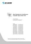
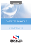
USER'S MANUAL
NEW UNI DC INVERTER
INDOOR CASSETTE UNITS
ASC-xxAIN
“Original instructions”
DC Inverter Cassette Type Air Conditioner Installation and Operation Manual
Read the following carefully to assure safe use.
NOTE: Children should be supervised to ensure that they do not play with the appliance.
DC Inverter Cassette Type Air Conditioner Installation and Operation Manual
NOTE: This appliance is not intended for use by persons (including children) with reduced physical, sensory
or mental capabilities, or lack of experience and knowledge, unless they have been given supervision or
instruction concerning use of the appliance by a person responsible for their safety.
1 Safety Precautions
WARNING!
This mark indicates procedures which, if improperly performed, might lead to the
death or serious injury of the user.
CAUTION!
This mark indicates procedures which, if improperly performed, might possibly result
in personal harm to the user, or damage to property.
WARNING!
(1). Installation should be left to the dealer or another professional. Improper installation may cause
water leakage, electrical shock, or fire.
(2). Install the air conditioner according to the instructions given in this manual. Incomplete installation
may cause water leakage, electrical shock, or fire.
(3). Be sure to use the supplied or specified installation parts. Use of other parts may cause the unit to
come to lose, water leakage, electrical shock, or fire.
(4). Install the air conditioner on a solid base that can support the weight of the unit. An inadequate base
or incomplete installation may cause injury in the event the unit falls off the base.
(5). Electrical work should be carried out in accordance with the installation manual and the national
electrical wiring rules or code of practice. Insufficient capacity or incomplete electrical work may
cause electrical shock or fire.
(6). Be sure to use a dedicated power circuit. Never use a power supply shared by another appliance.
(7). For wiring, use a cable length enough to cover the entire distance with no connection. Do not use
an extension cord. Do not put other loads on the power supply, use a dedicated power circuit.
(Failure to do so may cause abnormal heat, electric shock or fire.)
(8). Use the specified types of wires for electrical connections between the indoor and outdoor units.
Firmly clamp the interconnecting wires so their terminals receive no external stresses. Incomplete
connections or clamping may cause terminal overheating or fire.
(9). After connecting interconnecting and supply wiring be sure to shape the cables so that they do not
put undue force on the electrical covers or panels. Install covers over the wires. Incomplete cover
installation may cause terminal overheating, electrical shock, or fire.
(10).If any refrigerant has leaked out during the installation work, ventilate the room. (The refrigerant
produces a toxic gas if exposed to flames.)
(11)..After all installation is complete, check to make sure that no refrigerant is leaking out. (The
refrigerant produces a toxic gas if exposed to flames.)
(12).When installing or relocating the system, be sure to keep the refrigerant circuit free from
substances other than the specified refrigerant (R410A), such as air. (Any presence of air or other
foreign substance in the refrigerant circuit causes an abnormal pressure rise or rupture, resulting in
injury.)
(13).During pump-down, stop the compressor before removing the refrigerant piping. If the compressor
is still running and the stop valve is open during pump-down, air will be sucked in when the
refrigerant piping is removed, causing abnormal pressure in the freezer cycle which will lead to
breakage and even injury.
(14).During installation, attach the refrigerant piping securely before running the compressor. If the
compressor is not attached and the stop valve is open during pump-down, air will be sucked in
when the compressor is run, causing abnormal pressure in the freezer cycle which will lead to
breakage and even injury.
(15).Be sure to establish an earth. Do not earth the unit to a utility pipe, arrester, or telephone earth.
Incomplete earth may cause electrical shock, or fire. A high surge current from lightning or other
sources may cause damage to the air conditioner.
(16)..Be sure to install an earth leakage breaker. Failure to install an earth leakage breaker may result in
electric shocks, or fire.
(17).This appliance is not intended for use by persons (including children) with reduced physical,
sensory or mental capabilities, or lack of experience and knowledge, unless they have been given
supervision or instruction concerning use of the appliance by a person responsible for their safety.
(18).Children should be supervised to ensure that they do not play with the appliance.
(19).If the supply cord is damaged, it must be replaced by the manufacturer, its service agent or
similarly qualified persons in order to avoid a hazard.
CAUTION!
(1). Do not install the air conditioner in a place where there is danger of exposure to inflammable gas
leakage. If the gas leaks and builds up around the unit, it may catch fire.
(2). Establish drain piping according to the instructions of this manual. Inadequate piping may cause
flooding.
(3). Tighten the flare nut according to the specified method such as with a torque wrench. If the flare
nut is tightened too hard, the flare nut may crack after a long time and cause refrigerant leakage.
2 Outline of the Unit and Main Parts
Indoor
1
2
3
4
1. Drainage device
5
6
2. Drainage pipe
3. Air flow flap
Outdoor
4. Connection pipe
Air inlet
5. Wireless Controller
6. Wired Controller
7. Big handle
7
8. Liquid Pipe
8
9. Gas pipe
9
10
Air outlet
11
Fig.1
10. Drainage pipe
11. Front Board
Wireless Remote Controller YB1FA
1 User notice
CAUTION !
① Make sure there is no obstruction between the wireless remote controller and the signal
receiver.
② The signal receiving distance of the wireless remote controller can be up to 10 metres.
③ Never drop or throw the wireless remote controller.
④ Never let any liquid flow into the wireless remote controller.
⑤ Never expose the wireless remote controller under the sunlight directly or where it is very
hot.
⑥ This is a general remote control, it could be used for multiple types (functions) of air
conditioners. For some models without the functions specified here, we preserve the right to
not to inform exclusively.
2 Control panel of the wireless remote controller
1
HOUR
ONOFF
Note: This remote controller is universal and can be used for multi‐functional air conditioning. If the button on the remote controller with the function which the air conditioner doesn’t have is pressed, the unit remains in its original operating mode.
2
3
4
5
6
8
10
11
7
9
12
13
14
1
Wireless Remote Controller YB1FA
No.
Name
1
Signal
transmitter
2
3
ON/OFF
button
MODE
button
Function Description
●● Signal transmitter
●● Press this button, and the unit will be turned on; press it once more, and the
unit will be turned off. When turning off the unit, the Sleep function will be
canceled, but the presetting time is still remained.
●● By pressing this button, Auto, Cool, Dry, Fan, Heat mode can be selected
circularly. Auto mode is default after power on. Under the Auto mode, the
setting temperature will not be displayed; Under the Heat mode, the initial
value is 28°C (82°F);Under other modes, the initial value is 25°C(77°F).
AUTO ;
COOL;
DRY;
FAN;
HEAT (only for cooling and heating unit)
- button
●● Preset temperature can be decreased by pressing this button. Pressing
and holding this button for more than 2 seconds can make the temperature
changed quickly until release this button and then transmit this order. The
temperature adjustment is unavailable under the Auto mode, but the order
can be sent by pressing this button. Centigrade setting range: 16-30;
Fahrenheit scale setting range 61-86.
+ button
●● Preset temperature can be increased by pressing this button. Pressing and
holding this button for more than 2 seconds can make the temperature
changed quickly until release the button and then transimit this order.
The temperature adjustment is unavailable under the Auto mode, but the
order can be sent by pressing this button. Centigrade setting range: 1630; Fahrenheit scale setting range 61-86.
4
●● By pressing this button, Auto, Low, Middle, High speed can be circularly
selected. After power on, Auto fan speed is default.
AUTO
●●
5
FAN button
Low speed
Middle speed
High speed
Note: Under the DRY mode, the fan will be kept running at the low speed
and the fan speed isn't adjustable.
Wireless Remote Controller YB1FA
●● Press this button to set up the swing angle, which circularly changes as below:
SWING
6
UP/DOWN
button
●● When the guide louver starts to swing up and down, if SWING funtions
is canceled, the air guide louver will stop and remains at the current
position.
●●
indicates the guide louver swings up and down among those five
directions.(Simplified SWING function applicable for some Fan Coil Units:
When the wireless remote controller is energized initially with the unit
under the OFF status, it should be set by pressing the + button and the
SWING button simultaneously, with the symbol
blinking twice. Then,
after the unit is turned on, this function can be activated by pressing the
SWING button, with the displayed symbol
indicating swing function is
on and without this displayed symbol indicating swing function is off.)
7
8
CLOCK
button
TIMER ON
button
●● By pressing this button, the clock is allowed to be set, with
blinking,
and then press the +/- button to adjust the clock within 5 seconds. If the
+/-button is pressed down constantly for more than 2 seconds, the clock
setting will be increased or decreased 10 minutes every 0.5 seconds.
After that, another press on the CLOCK button accepts the setting. 12:00
is the default, when the wireless remote controller is energized.
●● When TIMER ON is activated, ON will blink while the symbol
will
disappear. Within 5 seconds it is allowed to set the ON time by pressing
the +/- button. Each press will make the time increase or decrease one
minute. Besides, the time can also be set by pressing the +/- button
constantly. that is, in the early 2.5 seconds, the time will increase/
decrease quickly per single minute, and in the late 2.5, the time will
increase/decrease per ten minutes. After the desired time value is set,
press TIENE ON again to conform the setting within five seconds. After
that, another press on TIMER ON will cancel the setting. Prior to this
setting, the clock shall be set to the actual time.
●● Pressing this button can activate or deactivate the X-FAN function.
9
X-FAN
button
In Cool or Dry mode, by pressing this button,if " " is displayed, it
indicates the X-FAN function is activated. By repressing this button,
if " " disappears, it indicates the X-FAN function is deactivated. After
energization, X-FAN OFF is defaulted. If the unit is turned off, X-FAN can
be deactivated but can't be activated.
Wireless Remote Controller YB1FA
●● By pressing this button it is allowed to select displaying the indoor setting
temperature or the indoor ambient temperature.
●● Indoor setting temperature is default after the indoor unit is energized
initially.
10
TEMP
button
●● By pressing the TEMP button, when the temperature symbol
is
displayed, the indoor displayer will show the indoor setting temperature;
when
is displayed, it will show the indoor ambient temperature;
when
is invalidation, If current displays indoor ambient temperature,
if received the other remote control signal, it will display presetting
temperature, 5s later, will back to display the ambient temperature. (This
function is applicable to partial of models)
11
12
13
TIMER
OFF button
TURBO
button
SLEEP
button
●● By pessing this button it is available to go to the TIMER OFF settting
state with the same setting method as that of the TIMER ON, in which
case the OFF symbol blinks.
●● In the Cool or Heat mode, pressing this button can activate or deactivate
the TURBO function.When the TURBO fucntion is activated, its symbol
will be displayed; when the running mode or the fan speed is changed,
this function will be canceled automatically.(This function is applicable to
partial of models).
●● By pressing this button, Sleep On and Sleep Off can be selected. After
powered on, Sleep Off is defaulted. Once the unit is turned off, the Sleep
function is canceled. When Sleep is set to On, the symbol of SLEEP
will display.Under the Fan and Auto modes, this function is not available.
●● Press this button to select LIGHT on or off in the displayer. When the
14
LIGHT
LIGHT is set to on, the icon
button
in the displayer will be on. When the LIGHT is set to off, the icon
be disappeared and the indicating light in the displayer will be off.
will be displayed and the indicating light
will
3 Introduction for special function
●● About X-FAN function (This function is applicable to some special models)
This function indicates that moisture on evaporator of indoor unit will be blowed after the unit is
stopped to avoid mould.
This function indicates that moisture in the evaporator of the indoor unit will be blew out after
the unit is stopped so as to avoid mould.
① With X-FAN function ON: After turning off the unit by pressing ON/OFF button indoor fan
will continue running for severval minutes at low speed. In this period, press X-FAN button to stop
indoor fan directly.
② With X-FAN function OFF:After turning off the unit by pressing ON/OFF button, the
complete unit will be off directly.
●● About TURBO function (This function is applicable to some special models)
If the TURBO function is activated, the unit will run at high fan speed to perform cooling or
4
Wireless Remote Controller YB1FA
heating quickly so that the ambient temperature will approach the preset temperature as soon as
possible.
●● About lock
Press + and - buttons simultaneously to lock or unlock the keyboard. If the wireless remote
controller is locked, the icon will be displayed on it, in which case, any press will get no response
but with the mark blinking for three times. If the keyboard is unlocked, the mark will disappear.
●● About SWING UP/DOWN
① Press the Swing Up/Down button for more than 2 seconds and then the louvre will swing up
and down. After releasing the button, the louvre will stop swinging and keep the current status.
② When the louvre starts swinging, by pressing the Swing Up/Down button 2 seconds
later, the louvre will stop swinging directly; while, by pressing the Swing Up/Down button within 2
seconds, the louver will keep swinging.
●● About Change over switch between Fahrenheit and Centigrade
Under the OFF state of the unit, press MODE and - buttons simultaneously to switch between
°C and °F.
4 Replacement of batteries
along the arrowhead direction and push the back cover of
1 Slightly press the place with
the wireless remote controller.
2 Take out the used batteries.
3 Insert two new AAA 1.5V dry cell batteries and pay attention to their polarity.
4 Put back the cover of the wireless remote controller.
3
2
1
4
Notes!
① When changing the batteries, do not use the used or different-type batteries, otherwise, it
would cause some malfunction to the wireless remote controller.
② If the wireless remote controller will not be used for a long time, please take them out, and
don’t let the battery liquid damage the wireless remote controller.
③ The operation should be within the signal receiving range.
④ It should be placed 1m away from the TV set or stereo sound sets.
⑤ If the wireless remote controller can not operate normally, please take batteries out for 30s.
If the anomaly persists, please change them.
⑥ The battery must be removed from the appliance before it is scrapped.The batteries is to be
disposed of safely.
Wired Controller XK60
1 Introduction to the Wired Controller
Fig.1 Appearance of the Wired Controller
1.1 Appearance and LCD Icons
Fig.2 Appearance of the LCD
Wired Controller XK60
1.2 Introduction to the LCD Icons
Table 1
No.
Icons
Introduction
1
Left and right swing function
2
Up and down swing function
3
Air exchange function
4
Sleep function
5
Auto mode
6
COOL mode
7
DRY mode
8
FAN mode
9
HEAT mode
10
Health function
11
I-Demand function
12
Vacation function
13
Status display of master and slave wired controller
14
Shield function
The button operation, temperature setting, "On/Off" operation, "Mode"
setting, and "Save" setting are disabled.
15
Fan speed
16
Memory function
The unit will resume the original setting state after power recovery.
17
Turbo function
18
Energy-saving function
19
Ambient/setting temperature
2
Wired Controller XK60
20
Electric heater
21
Blow function
22
Defrosting function
23
Filter cleaning
24
Timer Setting
25
Keycard control / Detected status sensed by human body
26
Quiet function
27
Lock function
Wired Controller XK60
2 Press Buttons
2.1 Buttons
Fig.3 Press Buttons
2.2 Instruction to the Function of Press Buttons
Table 2
No.
Press Buttons
1
Enter/Cancel
2
▲
6
▼
3
Fan
4
Mode
5
Function
7
Timer
Timer setting
8
On/Off
Turn on/off indoor unit
4 mode
and 2 ▲
Memory
Function Introduction
① .Function selection and canceling;
② .Press it for 5s to enquiry the outdoor and indoor ambient temperature.
① .Running temperature setting of indoor unit, range :16~30°C
② .Timer setting, range:0.5-24hr
③ .Air function setting
④ .Save setting
⑤ .Clean setting
Select fan speed from high, mid-high, middle, mid-low, low and auto
levels.
Selection of the COOL, HEAT, FAN or DRY mode.
Switchover among these functions of SWING/AIR/SLEEP/HEALTH/
I-DEMAND/VACATION/TURBO/SAVE/E-HEATER/BLOW/QUIET
Press Mode and ▲ at the same time for 5s under the OFF state of the
unit to activate/deactivate memory function (If memory is set, indoor unit
will resume original setting state after power recovery. If not, indoor unit is
defaulted to be OFF after power recovery. Memory function is defaulted to
be ON)
2▲
and 6 ▼
Lock
Under the ON state of the unit without any malfunction or under the OFF
state of the unit, press ▲and ▼ buttons at the same time for 5s to go to
the lock state. In this case, any other buttons won’t respond the press.
Repress ▲ and ▼ again for 5s to quit the lock state.
4 mode
and 6 ▼
°F/°C
Under the OFF state of the unit, press the Mode and ▼ at the same time
for 5s to switch the temperature scale between Celsius and Fahrenheit.
Wired Controller XK60
3 OPERATION INSTRUCTION
3.1 On/off
Press the On/Off button to turn on or off the unit.
Notes:
① .The state shown in Fig.4 indicates the OFF state of the unit after energization.
② .The state shown in Fig.5 indicates the ON state of the unit after energization.
Fig.4 OFF State of the Unit
Fig.5 ON State of the Unit
3.2 Mode Setting
Under the ON state of the unit, press the Mode button to switch the operation modes as the
sequence shown in Fig.6:
Auto
Cooling
Dry
Fig.6
5
Fan
Heating
Wired Controller XK60
3.3 Temperature Setting
Press ▲ or ▼button to increase or decrease setting temperature under on-state of the unit. If
press either of them continuously, temperature will be increased or decreased by 1°C every 0.5s.
In Cooling, Dry, Fan and Heating mode, temperature setting range is 16°C~30°C.
In Auto mode, the setting temperature is un-adjustable.
As shown in Fig.7:
Fig.7 Temperature Setting
3.4 Fan Speed Setting
Press Fan button, fan speed of indoor unit will change as the sequence shown in Fig.8:
Low
Mid-low
Middle
Mid-high
High
Fig.8 Fan Speed Setting
6
Super-high
Auto
Wired Controller XK60
3.5 Right and Left Swing
Under the ON state of unit, press the Function button to select the “Right and Left Swing”
function option and then press the Enter/Cancel button to activate it.
When the Swing function is activated, press the Function button to select the "Right and Left
Swing" function option and then press the Enter/Cancel button to deactivate it.
Right and Left Swing function setting is as shown in Fig.9.
Unit On, no left-right swing
Press “Function” button to set
left-right swing function
Press “Enter/Cancel” button to
activate left-right swing function
Press “Enter/Cancel” button to
cancel left-right swing function
Press “Function” button to set
left-right swing function
Fig.9 Right and Left Swing Setting
7
Wired Controller XK60
3.6 Up and Down Swing
Under the ON state of unit, press the Function button to select the "Up and Down Swing"
function option and then press the Enter/Cancel to activate it.
When the Swing function is activated, press the Function button to select the "Up and Down
Swing" function option and then press the Enter/Cancel button to deactivate it.
Up and Down Swing function setting is as shown in Fig.10.
Unit On, no up-down swing
Press “Function” button to set
up-down swing function
Press “Enter/Cancel” button to
activate up-down swing function
Press “Enter/Cancel” button to
cancel up-down swing function
Press “Function” button to set
up-down swing function
Fig.10 Up and Down Swing Setting
3.7 Timer Setting
Timer “On” Setting:
It is intended to set when to start the unit. When the unit is OFF, press the Timer button, with
xx. Hour displayed and ON blinking, then press ▲/▼to adjust the timer, after that, press the Timer
button again to make a confirmation. If the Mode button is pressed prior to the confirmation, it will
switch to the Timer Off setting. After the timer Off setting, the LCD displays xx. Hour ON OFF,xx.
Hour indicating the time to start the unit, while the time to stop the unit won’t be displayed.
Timer “Off” Setting:
It is intended to set when to stop the unit. When the unit is On, press the Timer button, with xx.
Hour displayed and OFF blinking, then press ▲/▼to adjust the timer, after that, press the Timer
button again to make a confirmation. If the Mode button is pressed prior to the confirmation, it will
switch to the Timer On setting. After the timer On setting, the LCD displays xx. Hour ON OFF,xx.
Hour indicating the time to stop the unit, while the time to start the unit won’t be displayed.
8
Wired Controller XK60
Cancellation of Timer Setting: The timer setting can be canceled by press “Timer”. Then , xx.
Hour won’t be displayed.
Timer Setting under the ON state of the Unit is as shown in Fig.11:
Unit On, no timer function
Press “timer” button to activate
timer function
Press “Timer” button to set
timer off
adjust timer time
adjust timer time
Press “Mode” button to set
timer on
Fig.11 Timer Setting under the ON state of the Unit
Timer range: 0.5-24hr. Every press of the ▲ or ▼ button will make the setting time increased or
decreased by 0.5hr.If press either of them continuously, the setting time will automatically increase/
decrease by 0.5hr every 0.5s.
Notes:
① .When Timer On and Timer Off both are set, the displayed time is the Timer On setting for
the unit under the OFF state , or is the timer Off setting for the unit under the ON state .
② .Timer On setting starts when the unit under the ON state is turned off; Timer Off setting
starts when the unit under the OFF state is turned on.
3.8 Air Exchange Setting
How to activate the air exchange function:
Under the ON state of the unit, press the Function button to select the “AIR” function, with
the function symbol flashing, and then press ▲ or ▼ to adjust the “AIR” type, after that, press the
Enter/Cancel button to activate this function. When this function is activated, the symbol will be
displayed. Type 1 is the defaulted “AIR” type.
There are 10 “AIR” function types , but only 1-2 types are for the wireless remote controller.
9
Wired Controller XK60
1――The unit continuously runs for 60min, and fresh air valve runs for 6 min.
2――The unit continuously runs for 60min, and fresh air valve runs for 12 min.
3――The unit continuously runs for 60min, and fresh air valve runs for 18 min.
4――The unit continuously runs for 60min, and fresh air valve runs for 2 4 min.
5――The unit continuously runs for 60min, and fresh air valve runs for 30 min.
6――The unit continuously runs for 60min, and fresh air valve runs for 36 min.
7――The unit continuously runs for 60min, and fresh air valve runs for 42 min.
8――The unit continuously runs for 60min, and fresh air valve runs for 48 min.
9――The unit continuously runs for 60min, and fresh air valve runs for 54 min.
10――The unit continuously runs for 60min, and fresh air valve always runs.
How to deactivate the air exchange function:
When the “Air” function is activated, it can be deactivated in the way by firstly pressing the
Function button to select the “Air” function option with the “Air” symbol flashing, and then pressing
the Enter/Cancel button with the “Air” symbol disappeared.
Air Exchange setting is shown as in Fig.12:
Unit On, no Air function
Press “Enter/Cancel” button
to cancel air function
Press “Function” button to set
air function
Press “Function” button to
set air function
Fig.12 Air Exchange Setting
10
adjust air mode
Press “Enter/Cancel” button to
activate air function
Wired Controller XK60
3.9 Sleep Setting
Sleep on: Press the Function button under the ON state of the unit to select the “Sleep” function
option and then press the Enter/Cancel button to activate it.
Sleep off: When the Sleep function is activated, press the Function button to select the Sleep
function option and then press the Enter/Cancel button to deactivate this function.
Sleep setting is as shown in Fig.13 :
Unit On, no Sleep function
Press “Function” button to set
sleep function
Press “Enter/Cancel” button to
activate sleep function
Press “Enter/Cancel” button to
cancel sleep function
Press “Function” button to
set sleep function
Fig.13 Sleep Setting
Notes:
① .The Sleep function is defaulted to be OFF after power recovery.
② .The Sleep function is unavailable under the Fan mode.
③ .When the Quiet function is activated, the Quiet function will always keep ON no matter if the
Sleep function is activated or deactivated.
④ .Under the Cool mode, the Sleep function is ON, the setting temperature range can be
16~23°C, 24~27°C, 28~29°C or 30°C. Each of them has a different curve as shown in
Fig.14.
11
Wired Controller XK60
Temp./℃
e.g. If the setting temperature is 25°C, the temperature will rise by 1°C in each hour until it
reaches 27°C. 7 hours later, the temperature will drop to 26°C. After that, the unit will run at this
temperature.
31
30
29
28
27
26
25
24
23
22
21
20
19
18
17
16
0
1
2
3
4
5
6
7
8
9
10 11 12
Time/(hour)
Fig.14 Sleep Curve under the COOL Mode
Temp./℃
Under the Heat mode, the Sleep function is ON, the setting temperature range can be 16°C,
17~20°C, 21~27°C or 28~30°C. Each of them has a different curve as shown in Fig.15.
e.g. If the setting temperature is 22°C, the temperature will drop by 1°C in each hour until it
reaches 20°C. Then, the unit will run at this temperature
31
30
29
28
27
26
25
24
23
22
21
20
19
18
17
16
0
1
2
3
4
5
6
7
8
9
10 11 12
Time/(hour)
Fig.15 Sleep Curve under the HEAT Mode
Wired Controller XK60
3.10 Health Setting
Under unit on status, press “Function” button to select health function with “Health” icon
flashing. Press “Enter/Cancel” button to activate health function.
When health is on, press “Function” button to set function, with “health” icon flashing. Then
press the “Enter/Cancel” button to cancel health function.
How to set health function is shown in the Fig.16:
Unit On, no Health function
Press “Function” button to
set health function
Press “Enter/Cancel” button to
activate health function
Press “Enter/Cancel” button to
cancel health function
Press “Function” button to set
health function
Fig.16 Health Setting
Note:
① .The health function can be cancelled by turning off the unit.
② .The health function can not be cancelled by mode switching.
③ .After the unit is resumed, health function will be maintained.
3.11 I-Demand Setting
Under cooling mode, press “Function” button to select I-Demand function with “I-Demand” icon
flashing. Press “Enter/Cancel” button to activate I-Demand function.
When I-Demand is on, press “Function” button to set function, with “I-Demand” icon flashing.
Then press the “Enter/Cancel” button to cancel I-Demand function.
How to set I-Demand function is shown in the Fig.17:
13
Wired Controller XK60
Unit On, no I-Demand function
Press “Function” button to set
I-Demand function
Press “Enter/Cancel” button to
activate I-Demand function
Press “Enter/Cancel” button to
cancel I-Demand function
Press “Function” button to set
I-Demand function
Fig.17 I-Demand Setting
Note:
① .The I-Demand function can be cancelled by mode switch and unit ON/OFF.
② .After the unit is resumed, I-Demand function will be maintained.
③ .The I-Demand function can not be simultaneously set and can be cancelled by Sleep/Quiet
function.
④ .When the I-Demand function is set, the unit will run as per Auto fan speed. The Turbo fan
speed is not available.
⑤ .When the I-Demand function is set, the setting temperature 27°C can not be changed.
⑥ .When the setting temperature is shielded by the distant control, I-Demand function can not
be entered.
3.12 Vacation Setting
Vacation function: It’s used to keep the indoor ambient temperature and activate fast heating.
Under heating mode, press “Function” button to select Vacation function with “Vacation” icon
flashing. Press “Enter/Cancel” button to activate Vacation function.
When Vacation is on, press “Function” button to set function. Then press the “Enter/Cancel”
button to cancel Vacation function with no icon flashing.
How to set vacation function is shown in the Fig.18:
14
Wired Controller XK60
Unit On, no Vacation function
Press “Function” button to set
vacation function
Press “Enter/Cancel” button to
activate vacation function
Press “Enter/Cancel” button to
cancel vacation function
Press “Function” button to set
vacation function
Fig.18 Vacation Setting
Note:
① .The vacation function can be only set under heating mode.
② .The turbo function will be cancelled when the vacation function is set.
③ .The Sleep and Quiet function will be cancelled when the vacation function is set.
④ .After the unit is resumed, the vacation function will be maintained.
⑤ .When the vacation function is set, the setting temperature can not be shielded by the
distant control. In reverse, the vacation function can not be set when the distant shielding is
taking into effect.
⑥ .When the vacation function is set, the setting temperature shown on the wired controller is
8°C. The indoor fan will automatically run as per Auto fan speed.
⑦ .The vacation function can be cancelled when there is mode switching. The temperature will
go back to the original setting temperature prior to vacation function.
⑧ .Unit ON/OFF will not cancel the vacation function.
3.13 Turbo Function Setting
TURBO function: The unit at the highest fan speed can realize quick cooling or heating so that
room temperature can quickly approach the setting temperature.
In the COOL or HEAT mode, press the Function button to select the "Turbo" function option and
then press the Enter/Cancel button to activate it.
When the "Turbo" function is activated, it can be deactivated by firstly pressing the Function
15
Wired Controller XK60
button to select the "Turbo" option and then pressing the Enter/Cancel button.
Turbo function setting is as shown in Fig.19:
Unit On, no Turbo function
Press “Function” button to set
turbo function
Press “Enter/Cancel” button to
cancel turbo function
Press “Enter/Cancel” button to
activate turbo function
Press “Function” button to set
turbo function
Fig.19 Turbo Function Setting
Notes:
① .The Turbo function will not be deactivated due to power failure. In DRY, FAN and AUTO
modes, the Turbo function is unavailable and the function symbol won’t be displayed.
② .The Turbo function will be automatically deactivated as the Quiet function is activated.
③ .The FAN button can also be used to adjust Turbo function.
3.14 SAVE Function Setting
Energy Saving Function: Energy saving can make the air conditioner runs in a smaller
temperature range by setting lower limited value of setting temperature in the COOL or DRY mode
and upper limited value in the HEAT mode.
(1). Energy Saving Setting for Cooling
When the unit runs under the COOL or DRY mode, press the Function button to select the
“SAVE” function option, with “SAVE” flashing, and then press ▲ or ▼ to adjust the lower limit, after
that, press the Enter/Cancel button to activate this function.
(2). Energy Saving Setting for Heating
When the unit runs under the HEAT mode, press the Function button to select the “SAVE”
function option, with “SAVING” flashing, then press the Mode button to switch to the “SAVE” setting
for the HEAT mode and then press ▲ or ▼ to adjust the upper limit, after that, press the Enter/
16
Wired Controller XK60
Cancel button to activate this function.
The activated SAVE function can be deactivated by firstly pressing the “Function” button to
select the “SAVE” option and then pressing the “Enter/Cancel” button.
The energy saving setting is as shown in the Fig.20:
Unit On, no Save function
Press “Enter/Cancel” button to
activate save function
Press “Function” button to set
energy-saving temperature for
Cooling
adjust temperature
adjust temperature
Press "Mode" button to set
energy-saving temperature
for Heating.
Fig.20 SAVE Function Setting
Notes:
① .Under the Auto mode, when the “SAVE” function is activated, the unit will forcibly quit the
Auto mode and change to the current operation mode. Further, the “Sleep” function will be
deactivated when the “SAVE” function is activated.
② .During the “SAVE” setting, if the Function button is pressed down or there is not any
operation within 5s after the last button operation, the system will quit the “SAVE” setting
with the current setting data not saved.
③ .The “SAVE” function setting will be memorized in case of power failure.
④ .The lower limit for cooling is 16 °C and the upper limit for heating is 30°C.
⑤ .During the “SAVE” setting, if the expected setting temperature is out of the limit, then the
limit temperature always prevail.
17
Wired Controller XK60
3.15 E-HEATER Setting
E-HEATER: in the HEAT mode, “E-HEATER” function is allowed to be activated to improve the
heating efficiency. Generally, it will be activated automatically as the unit goes into the HEAT mode
through any button operations .
Activation of the “E-HEATER” Function: firstly press the Function button to select the
“E-HEATER” option, with the symbol “E-HEATER” flashing, and then press the Enter/Cancel button
to activate it. After the activation, the symbol “E-HEATER” will always be displayed.
Deactivation of the “E-HEATER” Function: firstly press the Function button to select the
“E-HEATER” option, with the symbol “E-HEATER” flashing, and then press the Enter/Cancel button
to deactivate it.
“E-HEATER” Function setting is as shown in Fig.21:
Unit On, no E-heater function
Press “Function” button to set
E-heater function
Press “Enter/Cancel” button to
activate E-heater function
Press “Enter/Cancel” button to
cancel E-heater function
Press “Function” button to set
E-heater function
Fig.21 “E-HEATER” Function Setting
Note: The “E-HEATER” function is not available in the COOL, DRY, and FAN modes, with the
symbol “E-HEATER” not displayed.
3.16 Blow Function Setting
BLOW function: After the unit is turned off, water in evaporator of indoor unit will be
automatically evaporated to avoid mildew.
Activation of the “Blow” Function: in the COOL or DRY mode, press the Function button to
select the “Blow” option, with the symbol “BLOW” flashing, and then press the Enter/Cancel button
to activate it.
18
Wired Controller XK60
Deactivation of the “Blow” Function: The activated “Blow” function can be deactivated by firstly
pressing the Function button to select the “Blow” option and then pressing the Enter/Cancel button.
BLOW function setting is as shown in Fig.22:
Unit On, no Blow function
Press “Function” button to set
blow function
Press “Enter/Cancel” button to
activate blow function
Press “Enter/Cancel” button to
cancel blow function
Press “Function” button to set
blow function
Fig.22 Blow Function Setting
Notes:
① .When the “Blow” function is activated, if the unit is turned off through the On/Off button, the
indoor fan will still run at low fan speed for another 10 minutes. When the “Blow” function is
deactivated, the indoor fan will stop directly as the unit is turned off.
② .The “Blow” function is not available in the FAN and HEAT modes.
3.17 Filter Setting
Under On status, press “Function” button to set “Filter” function with “Filter” icon flashing. The
setting pollution level will be shown at the Timer area. Press “▲” and “▼” to adjust pollution level
and press “Enter/Cancel” button to activate Filter function.
When the Filter function is set, press “Function” button to set with “Filter” icon flashing. Press “▲”
and “▼” to adjust till “00” is shown on the timer area. Then press “Enter/Cancel” button to cancel
the Filter function.
How to set Filter function is shown in the Fig.23:
19
Wired Controller XK60
Unit On, no Filter function
“00” shown at the timer area
Press “Function” button to set
filter function
the pollution level
Press “Function” button to set
filter function
Press “Enter/Cancel” button
to activate filter function
Press “Enter/Cancel” button to
cancel filter function
Fig.23 Filter Setting
While setting Filter, two numbers will be shown on the timer area. The first number represents
the pollution level. The second number shows the accumulated operating time of the indoor fan.
There are four statuses in total:
① .No Filter function setting ( “00” shown at the timer area)
② .When the filter reaches light-level pollution, “1” will be shown at the first place, When “0”
shows up at the second place, the accumulated operating hour reaches 5500h. Every
increase of the number means another 500h is accumulated. When “9” shows up, it means
the operating hour reaches 10000h.
③ .When the filter reaches middle-level pollution, “2” will be shown at the first place, When
20
Wired Controller XK60
“0” shows up at the second place, the accumulated operating hour reaches 1400h. Every
increase of the number means another 400h is accumulated. When “9” shows up, it means
the operating hour reaches 5000h.
④ .When the filter reaches serious-level pollution, “3” will be shown at the first place, When
“0” shows up at the second place, the accumulated operating hour reaches 100h. Every
increase of the number means another 100h is accumulated. When “9” shows up, it means
the operating hour reaches 1000h.
Pollution level with corresponding operating hour:
Table 3
Pollution Accumulated operating Pollution Accumulated operating Pollution Accumulated operating
level
time (h)
level
time (h)
level
time (h)
10
5500
20
1400
30
100
11
6000
21
1800
31
200
12
6500
22
2200
32
300
13
7000
23
2600
33
400
14
7500
24
3000
34
500
15
8000
25
3400
35
600
16
8500
26
3800
36
700
17
9000
27
4200
37
800
18
9500
28
4600
38
900
19
10000
29
5000
39
1000
Note:
icon will light up.
① .If the Filter function is effectively set, the
② .If it is not necessary to clean the filter, no matter whether the setting is changed or not, the unit will not
restart to timing while pressing “Enter/Cancel” button.
icon will blink once every 0.5s so as to
③ .If the filter should be cleaned, under On/OFF status, the
remind user to clean the filter. Press “Function” button to set with icon
flashing. Press “▲” and
“▼” to adjust pollution level, and then press “Enter/Cancel” button to activate it. If the setting pollution
level is lighter than before, the icon
will keep flashing. If the setting pollution level is more
serious, the icon
will go out, and the Filter function will keep on working.
flashing, let
④ .The only method to cancel Filter function is, when the function is set with icon
“00”shown at the timer area, at this time, the accumulated time will be zero clearing.
3.18 Quiet Function Setting
Press “Function” button to set Quiet function with its icon flashing. Press “Enter/Cancel” button
to activate Quiet function.
When the quiet function is On, press “Function” button to set with Quiet icon flashing, press
“Enter/Cancel” button to cancel Quiet function.
How to set Quiet function is set in the Fig. 24:
Wired Controller XK60
Unit On, no Quiet function
Press “Function” button to set
quiet function
Press “Enter/Cancel” button to
activate quiet function
Press “Enter/Cancel” button to
cancel quiet function
Press “Function” button to set
quiet function
Fig.24 Quiet function setting
Notes:
① ."QUIET" function is unavailable in Fan or Dry mode. Owing to power failure, the "Quiet"
function is defaulted to be deactivated.
② .If quite function is set, turbo function will be canceled.
3.19 Ultra-Dry Setting
Under Dry mode, when the setting temperature is 16°C, press “▼” button twice and the setting
temperature will be changed to 12°C, at this time, the unit enters the Ultra-Dry function.
When the Ultra-Dry function is activated, it can be cancelled by pressing “▲” button or pressing
“Mode” button to switch mode.
3.20 Other Functions
3.20.1 Lock Function
Under the ON state of the unit without any malfunction or under the OFF state of the unit, press
▲ and ▼buttons at the same time for 5s till the wired controller enters the lock state. In this case,
LCD displays
. After that, repress these two buttons at the same time for 5s to quit the lock
state.
Under the lock state, no response will be given to the other button operation.
22
Wired Controller XK60
3.20.2 Memory Function
Memory switchover: Under the OFF state of the unit, press the Mode and ▲ buttons at the
same time for 5s to switch memory modes. When setting the memory mode, “MEMORY” will be
displayed. If this function is deactivated, the unit will go to the OFF state after power recovery.
Memory recovery: If the memory function is On, the wired controller after power failure will
resume its original running state upon power recovery.
Note: It will take about 5 seconds to save data. Therefore, please do not cut down the power at this
time, or data will fail to be saved.
3.20.3 Selection of Centigrade and Fahrenheit
Under the OFF state of the unit, press the Mode and ▼ buttons at the same time for 5s,
Centigrade and Fahrenheit scales will be switched alternately.
3.20.4 Ambient Temperature Enquiry
Under On/Off status, press “Confirm” button for 5s, it will enter Enquiry interface. At this time,
what shows on the timer area is the ambient temperature type: 01 or 02 and the temperature will
be shown. “01” means the outdoor ambient temperature and “02” represents the indoor ambient
temperature. Press “Mode” button to switch between those two types. Press any other button
except Mode button or receive the signal from the remote controller will quit from the Enquiry
function. If there is no operation in 20s, the unit will quit from this function automatically.
Note:
① .If the unit is not connected with the ambient temperature sensor, after 12h electrification,
the display of the ambient temperature sensor will be shielded.
② .If the outdoor temperature sensor has error, after 12h electrification, the display of the
ambient temperature sensor will be shielded.
3.20.5 Indoor fan shutdown mode setting
Under unit OFF status, simultaneously press “Function” and “Timer” button for 5s, the wired
controller will enter parameter setting interface. Press “Mode” button to set till “05” is shown on the
temperature displayed area. Then the unit will enter the indoor fan shutdown mode.
Two options are available for the indoor fan shutdown mode:
Mode 1: When the temperature reaches certain value, the indoor fan will not be shut down
at any mode except heating mode. After the unit is shut down, for the duct type unit and the floor
ceiling type unit, the indoor fan will blow the extra heat for 60s and then stop running. For the
cassette type unit, its indoor fan will operate at low fan speed and blow the extra heat for 60s only
when error happens to it.
Mode 2: No matter the unit is under which mode, the indoor fan will keep running for 10s after
the temperature reaches certain value, then it will stop.
Press “▲” or “▼” button to adjust the mode. Under Mode 1/2, “00”/ “01” will show up in the
timer area. Then press “Enter/Cancel” button to save the settings. The setting procedures are
shown as Fig.25:
23
Wired Controller XK60
Unit off
Simultaneously press “Function”
and “Timer” button for 5s, the
wired controller will enter
parameter setting interface.
Press “Mode” button to set till
“05” is shown on the temperature
displayed area. Then the unit will
enter the indoor fan shutdown mode.
Press “Enter/Cancel” button to
save the settings and quit from
the interface.
Fig.25 Indoor fan shutdown mode setting
Note: In the parameter setting interface, only when “05” shown on it, the indoor fan shutdown mode
can be set. Other parameters are not allowed to be modified and our company is not responsible
for the unit damage or property loss due to parameter changed by customers.
4 Installation of the Wired Controller
4.1 Standard Parts
Table 4 Standard Parts
Fig.26 Standard Parts of the Wired Controller
24
No.
Description
Quantity
1
Base Box
1
2
Soleplate
1
3
Screw M4×25
2
4
Front Panel
1
Wired Controller XK60
4.2 Installation Location and Installation Requirements
(1). Do not install the wired controller in the damp place or under direct sunlight.
(2). Do not install the wired controller close to the hi-temperature object or place where the
wired controller is likely to suffer water spray.
(3). Do not install the wired controller directly opposite to the window so as to avoid improper
operation caused by the interference of the neighbor’s same model wired controller.
(4). Please cut off the power supply of wires embedded in the wall. No operation is allowed with
electricity.
(5). To avoid abnormal operation caused by electromagnetic interference or other causes,
please take notice of the following statements during wiring.
① .Be sure the communication line is wired into the correct port, otherwise it would result in
communication fault.
② .The communication line (wired controller) and power line must be separated with the
minimal distance of 20cm, otherwise it would result in communication fault.
③ .Suppose that the air conditioner is installed where likely to suffer electromagnetic
interference, the communication line of the wired controller must be shielded twisted pair.
4.3 How to Install the Wired Controller
First of all, the selection and connecting method of the communication line is shown as follows:
(1). Select appropriate communication line of the wired controller: 2-core signal line (wire
size≥0.75mm2, length<30m, recommended length: 8m).
(2). After the indoor unit is de-energized, fix the communication line on the indoor terminal
board by screws.
Then, the specific installation steps is shown in the Fig.27:
Fig.27 Installation of the Wired Controller
Wired Controller XK60
Brief instructions:
① .Pull out the 2-core signal line from the mounting hole and pass this line through the round
hole located at the bottom of the wired controller.
② .Use M4×25 screws to fix the soleplate of the wired controller on the wall.
③ .Fix the signal line on the copper tabs X1 and X2. Make sure the line is tightly fixed and with
no short-circuit potential.
④ .Set the panel and the bottom together by clasps.
4.4 How to Remove the Wired Controller
The wired controller can be easily removed as shown in Fig.28
Fig.28 Removal of the Wired Controller
5 Error Display
When error happens to the unit, the error code will be shown on the wired controller. When
multiple errors simultaneously happen, the error codes will circularly show up.
When error occurs, please immediately shut down the unit and contact professional personnel.
As shown in the Fig.29 means the high pressure protection.
Fig.29
26
Wired Controller XK60
Error codes and their meanings:
Table 5
Number
Error code
Error
1
E1
Compressor high pressure protection
2
E2
Indoor anti-freeze protection
3
E3
Compressor low pressure protection, refrigerant lack protection and
refrigerant colleting mode
4
E4
Compressor high discharge temperature protection
5
E6
Communication error
6
E8
Indoor fan motor error
7
E9
Full water protection
8
F0
Indoor ambient temperature sensor error
9
F1
Evaporator temperature sensor error
10
F2
Condenser temperature sensor error
11
F3
Outdoor ambient temperature sensor error
12
F4
Discharge temperature sensor error
13
F5
Temperature sensor error of wired controller
14
C5
Capacity code error
15
EE
Outdoor memory chip error
16
PF
Electric box sensor error
17
H3
Compressor overload protection
18
H4
Overloading
19
H5
IPM protection
20
H6
DC fan motor error
21
H7
Drive desynchronizing protection
22
Hc
Pfc protection
23
L1
Humidity sensor error
24
Lc
Activation failure
25
Ld
Compressor phase sequence protection
26
LF
Power protection
27
Lp
Indoor and outdoor mismatch
28
U7
4-way valve direction changing protection
29
P0
Drive reset protection
30
P5
Over-current protection
31
P6
Communication error between main control and drive
32
P7
Drive module sensor error
Wired Controller XK60
33
P8
Drive module over temperature protection
34
P9
Zero passage protection
35
PA
AC current protection
36
Pc
Drive current error
37
Pd
Sensor connecting protection
38
PE
Temperature drift protection
39
PL
Bus low voltage protection
40
PH
Bus high voltage protection
41
PU
Charge loop error
42
PP
Input voltage abnormality
43
ee
Drive memory chip error
  Instructions to the Error Indicating Lamps on the Panel of the Cassette Type Unit.
Receiver
"88" Dispaly
"Auto" Button
Power
Indicating Lamp
Timer
Indicating Lamp
"Test" Button
Fig.46
◆◆ Power and ON/OFF Indicating Lamp:
It goes red when the unit is powered on while it goes white when the unit is started.
◆◆ Timer Indicating Lamp:
It goes on when the timer is set and goes off when it is not. Its display is in yellow.
◆◆ “88” Display:
When there is no error, and it receives valid remote control information. It will display the temp
setup for 5s, then display the temp of indoor. When the unit has error, It will display the error code.
When there are more than one error, the error code will be displayed alternately.
After the grille of the front panel is opened, the front panel is still allowed to realize the following
functions by pressing the “Auto” button and the nearby “Test” button simultaneously for five seconds
when the unit is “Off”.
6.2 Working Temperature Range
Table12
Test Condition
Indoor Side
Outdoor Side
DB(°C)
WB(°C)
DB(°C)
WB(°C)
Nominal Cooling
27
19
35
24
Nominal Heating
20
−
7
6
Rated Cooling
32
23
48
−
Low Temp. Cooling
21
15
-15
−
Rated Heating
27
−
24
18
Low Temp. Heating
20
−
-10
-11
Note:
① .The design of this unit conforms to the requirements of EN14511 standard.
② .The air volume is measured at the relevant standard external static pressure.
③ .Cooling (heating) capacity stated above is measured under nominal working conditions
corresponding to standard external static pressure. The parameters are subject to change with
the improvement of products, in which case the values on nameplate shall prevail.
④ .In this table, there are two outside DB values under the low temp cooling conditions, and the
one in the brackets is for the unit which can operate at extreme low temperature.
7 Troubleshooting and Maintenance
7.1 Troubleshooting
If your air-conditioning unit suffers from abnormal operation or failure, please first check the
following points before repair:
Table 13
Failure
Possible Reasons
① .The power supply is not connected.
② .Electrical leakage of air-conditioning unit causes tripping of the leakage
The unit cannot be started.
switch.
③ .The operating keys are locked.
④ .The control loop has failure.
① .There is obstacle in front of the condenser.
The unit operates for a
while and then stops.
② .The control loop is abnormal.
③ .Cooling operation is selected when the outdoor ambient temperature is
above 48°C.
① .The air filter is dirty or blocked.
② .There is heat source or too many people inside the room.
③ .The door or window is open.
Poor cooling effect.
④ .There is obstacle at the air intake or outlet.
⑤ .The set temperature is too high.
⑥ .There is refrigerant leakage.
⑦ .The performance of room temperature sensor becomes worse
① .The air filter is dirty or blocked.
② .The door or window is not firmly closed.
Poor heating effect
③ .The set room temperature is too low.
④ .There is refrigerant leakage.
⑤ .The outdoor ambient temperature is lower than -5°C.
⑥ .Control loop is abnormal.
Note: After carrying out the check of the above items and taking relevant measures to solve the
problems but the air-conditioning unit still does not function well, please stop the operation of the
unit immediately and contact the local service agency designated by Sinclair Ltd.
Only ask professional serviceman to check and repair the unit.
DC Inverter Cassette Type Air Conditioner Installation and Operation Manual
The following are not troubles:
7.2 Routine Maintenance
Only a qualified service person is allowed to perform maintenance.
Before accessing to terminal devices, all power supply circuits must be disconnected.
Do not use water or air of 50°C or higher for cleaning air filters and outside panels.
Notes:
① .Do not operate the air conditioner with the filter uninstalled, otherwise dust would come into
the unit.
② .Do not remove the air filter except for cleaning. Unnecessary handling may damage the filter.
③ .Do not clean the unit with gasolene, benzene, thinner, polishing powder or liquid insecticide,
otherwise it would cause discoloration and deformation of the unit.
④ .Do not wet the indoor unit in case of electric shock or fire hazard.
Increase the frequency of cleaning if the unit is installed in a room where the air is extremely
contaminated.(As a yardstick for yourself, consider cleaning the filter once a half year.)
If dirt becomes impossible to clean, change the air filter.
How to clean the air filter
1. Open the air inlet grille
(1).  How to open the panel grille of the
24K~42K cassette type unit
① .Push the buckle as shown in the
figure.
Remove the screw
② .Release the screws under buckles by
a screwdriver.
③ .Push the fastener and open the panel
grille.
Push the fastener
(2).  How to open the panel grille of the
12K\18K\48K\60K cassette type unit
① .Remove the screws by a screwdriver
as shown in the picture.
② .Push those two fasteners and open
the panel grille.
Remove the screw
Push the fastener
2. Disassemble the air inlet grille
Open the air inlet grille at 45°, raise it and
remove the grille.
3. Disassemble the filter screen
Draw out the filter screen and remove it.
Filter screen
4. Disassemble the air purifier
Remove the air purifier after removing the
fixed screws on it.
Filtering element
Support
Bolt
5. Clean the filer screen
Clean the filer screen by a vacuum cleaner
or wash it by flashing water. If the oil stain
on the filter can not be removed or cleaned
up, wash it by warm water meld with the
detergent. Dry the filer in the shadow.
Note:
Never use hot water over 45°C in case of
color fading or turning yellow.
Never dry it by fire so as to prevent the filter
caught fire or deformation.
6. Reset the filer
The same as step 3
7. Install the grille well
The same as step 1 and 2
32
DC Inverter Cassette Type Air Conditioner Installation and Operation Manual
10. Optimum Operation
DC Inverter Cassette Type Air Conditioner Installation and Operation Manual
11. Care and Maintenance(It should be done by professionals)
DC Inverter Cassette Type Air Conditioner Installation and Operation Manual
DC Inverter Cassette Type Air Conditioner Installation and Operation Manual
DC Inverter Cassette Type Air Conditioner Installation and Operation Manual
Operate on unmentioned buttons would not impact on the normal use.
Take-back of electrical waste
Information for Users to Disposal of electrical and electronic equipment
(private households)
Icon on the product or in the accompanying documentation means that used electric or electronic products
must not be disposed together with domestic waste. For the correct disposal of the product hand it over to a
place for take-back, where it is collected free of charge. By correct disposal of the product you can help to
preserve valuable natural resources and help in preventing potential negative impacts to environment and
human health, which could be consequence of incorrect disposal of waste. Ask for more details from local
authorities, nearest collection point, in Waste Acts of respective country, in the Czech Republic in Act no.
185/2001 Coll., in the wording of later regulations. In case of incorrect disposal of this waste, a fine can be
imposed according to national regulations.
Manufacturer:
Sinclair Corporation Ltd., 1-4 Argyll Street,
London W1F 7LD, UK
Supplier and technical support:
Nepa, spol.s.r.o.
Purky ova 45
612 00 Brno
Czech Republic
www.nepa.cz
Toll-free info line:
+420 800 100 285