1
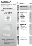
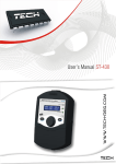
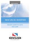
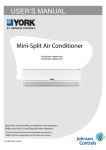
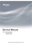
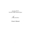
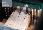
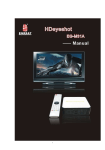
USER'S MANUAL NEW UNI DC INVERTER INDOOR DUCT UNITS ASD-xxAIN Original instructions TRACE SERIES Safety Precautions WARNING! This mark indicates procedures which, if improperly performed, might lead to the death or serious injury of the user. CAUTION! This mark indicates procedures which, if improperly performed, might possibly result in personal harm to the user, or damage to property. WARNING! (1). For operating the air conditioner pleasantly, install it as outlined in this installation manual. (2). Connect the indoor unit and outdoor unit with the room air conditioner piping and cord available from our standard parts. This installation manual describes the correct connections using the installation set available from our standard parts. (3). Installation work must be performed in accordance with national wiring standards by authorized personnel only. (4). If refrigerant leaks while work is being carried out, ventilate the area. If the refrigerant comes in contact with a flame, it produces toxic gas. (5). Do not power on until all installation work is complete. (6). During installation, make sure that the refrigerant pipe is attached firmly before you run the compressor. Do not operate the compressor under the condition of refrigerant piping not attached properly with 2-way or 3-way valve open. This may cause abnormal pressure in the refrigeration cycle that leads to breakage and even injury. (7). During the pump-down operation, make sure that the compressor is turned off before you remove the refrigerant piping. Do not remove the connection pipe while the compressor is in operation with 2-way or 3-way valve open. This may cause abnormal pressure in the refrigerant cycle that leads to breakage and even injury. (8). When installing and relocating the air conditioner, do not mix gases other than the specified refrigerant (R410A) to enter the refrigerant cycle. If air or other gas enters the refrigerant cycle, the pressure inside the cycle will rise to an abnormally high value and cause breakage, injury, etc. (9).This appliance is not intended for use by persons (including children) with reduced physical, sensory or mental capabilities, or lack of experience and knowledge, unless they have been given supervision or instruction concerning use of the appliance by a person responsible for their safety. (10).Children should be supervised to ensure that they do not play with the appliance. (11).If the supply cord is damaged, it must be replaced by the manufacturer, its service agent or similarly qualified persons in order to avoid a hazard. Outline of the Unit and Main Parts Indoor Air outlet Air inlet 1 2 5 3 1. power Cord 4 2. Electric Box 3. Wired controller Outdoor 4. Wireless Controller Air inlet 5. Binding tape 6. Drain Pipe 7. Gas Pipe 8. Lipuid Pipe 9. Big Handle 10. Front Board Air outlet 10 9 8 7 6 Fig.1 NOTE! ① .The connection pipe and duct for this unit should be prepared by the user. ② .The unit is standard equipped with rectangular duct. WIRELESS REMOTE CONTROLLER Operation and Display View HOUR ONOFF Note: This remote controller is universal and can be used for multi‐functional air conditioning. If the button on the remote controller with the function which the air conditioner doesn’t have is pressed, the unit remains in its original operating mode. Table Operation instruction of wireless remote controller No. Name Signal transmitter ON/OFF button MODE button Function Description Signal transmitter z Press this button and the unit will be turned on; press it once more, and the unit will be turned off. When turning z off the unit, the Sleep function will be canceled, but the presetting time is still remained. By pressing this button, Auto, Cool, Dry, Fan, Heat mode can be selected circularly. Auto mode is default after z power on. Under the Auto mode, the setting temperature will not be displayed; Under the Heat mode, the initial value is 28°C (82°F);Under other modes, the initial value is 25°C(77°F). AUTO; COOL; DRY; FAN; HEAT (only for cooling and heating unit) - button Preset temperature can be decreased by pressing this button. Pressing and holding this button for more than 2 z seconds can make the temperature changed quickly until release this button and then transmit this order. The temperature adjustment is unavailable under the Auto mode, but the order can be sent by pressing this button. Centigrade setting range: 16-30; Fahrenheit scale setting range 61-86. + button Preset temperature can be increased by pressing this button. Pressing and holding this button for more than 2 z seconds can make the temperature changed quickly until release the button and then transmit this order. The temperature adjustment is unavailable under the Auto mode, but the order can be sent by pressing this button. Centigrade setting range: 16-30; Fahrenheit scale setting range 61-86. By pressing this button, Auto, Low, Middle, High speed can be circularly selected. After power on, Auto fan z speed is default. AUTO FAN button Ɣ Low speed Middle speed High speed Note: Under the DRY mode, the fan will be kept running at the low speed and the fan speed isn't adjustable. Press this button to set up the swing angle, which circularly changes as below: z SWING UP/DOWN button When the guide louver starts to swing up and down, if SWING functions is canceled, the air guide louver will z stop and remains at the current position. z indicates the guide louver swings up and down among those five directions.(Simplified SWING function applicable for some Fan Coil Units: When the wireless remote controller is energized initially with the unit under the OFF status, it should be set by pressing the + button and the SWING button simultaneously, with the symbol blinking twice. Then, after the unit is turned on, this function can be activated by pressing the SWING button, indicating swing function is on and without this displayed symbol indicating swing with the displayed symbol function is off.) CLOCK button blinking, and then press the +/- button to adjust By pressing this button, the clock is allowed to be set, with z the clock within 5 seconds. If the +/-button is pressed down constantly for more than 2 seconds, the clock setting will be increased or decreased 10 minutes every 0.5 seconds. After that, another press on the CLOCK button accepts the setting. 12:00 is the default, when the wireless remote controller is energized. will disappear. Within 5 seconds it is allowed When TIMER ON is activated, ON will blink while the symbol z to set the ON time by pressing the +/- button. Each press will make the time increase or decrease one minute. TIMER ON button Besides, the time can also be set by pressing the +/- button constantly. that is, in the early 2.5 seconds, the time will increase/decrease quickly per single minute, and in the late 2.5, the time will increase/decrease per ten PLQXWHV$IWHUWKHGHVLUHGWLPHYDOXHLVVHWSUHVV7,(1(21DJDLQWRFRQIRUPWKHVHWWLQJZLWKLQ¿YHVHFRQGV After that, another press on TIMER ON will cancel the setting. Prior to this setting, the clock shall be set to the actual time. Pressing this button can activate or deactivate the X-FAN function. In Cool or Dry mode, by pressing this button, z X-FAN button if " " is displayed, it indicates the X-FAN function is activated. By repressing this button, if " " disappears, it indicates the X-FAN function is deactivated. After energization, X-FAN OFF is defaulted. If the unit is turned off, X-FAN can be deactivated but can't be activated. By pressing this button it is allowed to select displaying the indoor setting temperature or the indoor ambient z temperature. Indoor setting temperature is default after the indoor unit is energized initially. z TEMP button By pressing the TEMP button, when the temperature symbol z the indoor setting temperature; when is displayed, the indoor displayer will show is displayed, it will show the indoor ambient temperature; when is invalidation, If current displays indoor ambient temperature, if received the other remote control signal, it will display presetting temperature, 5s later, will back to display the ambient temperature. (This function is applicable to partial of models) TIMER OFF button TURBO button SLEEP button LIGHT button By pressing this button it is available to go to the TIMER OFF setting state with the same setting method as that z of the TIMER ON, in which case the OFF symbol blinks. In the Cool or Heat mode, pressing this button can activate or deactivate the TURBO function. When the z TURBO function is activated, its symbol will be displayed; when the running mode or the fan speed is changed, this function will be canceled automatically.(This function is applicable to partial of models). By pressing this button, Sleep On and Sleep Off can be selected. After powered on, Sleep Off is defaulted. z Once the unit is turned off, the Sleep function is canceled. When Sleep is set to On, the symbol of SLEEP will display. Under the Fan and Auto modes, this function is not available. Press this button to select LIGHT on or off in the displayer. When the LIGHT is set to on, the icon z will be displayed and the indicating light in the displayer will be on. When the LIGHT is set to off, the icon disappeared and the indicating light in the displayer will be off. will be WIRED CONTROLLER Display View Figure 2-3-1 Appearance of wired controller Figure 2-3-2 LCD display of wired controller Table Instruction to LCD Display No. Icons Introduction 1 Left and right swing function 2 Up and down swing function 3 Air exchange function 4 Sleep function 5 Auto mode 6 COOL mode 7 DRY mode 8 FAN mode 9 HEAT mode 10 Health function 11 I-Demand function 12 Vacation function 13 Status display of master and slave wired controller 14 Shield function The button operation, temperature setting, "On/Off" operation, "Mode" setting, and "Save" setting are disabled. 15 Fan speed 16 Memory function The unit will resume the original setting state after power recovery. 17 Turbo function 18 Energy-saving function 19 Ambient/setting temperature 20 Electric heater 21 Blow function 22 Defrosting function 23 Filter cleaning 24 Timer Setting 25 Keycard control / Detected status sensed by human body 26 Quiet function 27 Lock function Operation View Silk Screen of Buttons Instruction to Function of Buttons Table Instruction to buttons of wired controller No. Description Functions 1 Enter/Cancel ķ Function selection and canceling; ĸ Press it for 5s to view the ambient temperature; press Mode button to select viewing outdoor ambient temperature or indoor ambient temperature. 2 Ÿ 6 ź 3 Fan 4 Mode 5 Function 7 Timer Timer setting. 8 On/Off Turn on/off indoor unit. ķ Running temperature setting range of indoor unit: 16-30°C; ĸ Timer setting range: 0.5-24hr; Ĺ Setting of air function level; ĺ Setting of energy-saving temperature; Ļ Setting of cleaning class. Setting of high/medium high/medium/medium low/low/auto fan speed. Setting of auto/cooling/heating/fan/dry mode of indoor unit. Switch over among these functions of swing/air/sleep/health/ I-Demand/out/turbo/save/ e-heater/X-fan/clean/quiet. 4 Mode and Ÿ Memory function 3UHVV0RGHDQGŸEXWWRQVDWWKHVDPHWLPHIRUVXQGHURIIVWDWHRIWKHXQLWWRHQWHU cancel memory function (If memory function is set, indoor unit will resume original setting state after power failure and then power recovery. If not, indoor unit is defaulted to be off after power recovery. Ex-factory setting of memory function is on). Ÿ and ź Lock 8SRQVWDUWXSRIWKHXQLWZLWKRXWPDOIXQFWLRQRUXQGHURIIVWDWHRIWKHXQLWSUHVVŸDQGź buttons at the same time for 5s to enter lock state. In this case, any other buttons won’t UHVSRQGZKHQSUHVVLQJ5HSUHVVŸDQGźEXWWRQVIRUVWRTXLWORFNVWDWH 4 Mode and 5 Function Enquiry and setting of address of wired controller Under off state of the unit, press Mode and Function buttons at the same time for 5s to set the address. (More details please refer to project debugging) 5 Function and 7 Timer Setting of project parameters (More details please refer to the Notes) Under off state of the unit, press Function and Timer buttons at the same time for 5s to JRWRWKHGHEXJJLQJPHQX3UHVV0RGHEXWWRQWRDGMXVWWKHVHWWLQJLWHPVDQGSUHVVŸRU źEXWWRQVWRVHWWKHDFWXDOYDOXH 4 Mode and ź Switch between Fahrenheit and Centigrade 8QGHURIIVWDWHRIWKHXQLWSUHVV0RGHDQGźEXWWRQVDWWKHVDPHWLPHIRUVWRVZLWFK between Fahrenheit and Centigrade. 5 Function and ź Viewing historical malfunction &RQWLQXRXVO\SUHVV)XQFWLRQDQGźEXWWRQVIRUVWRYLHZKLVWRULFDOPDOIXQFWLRQ7KHQ SUHVV Ÿ DQG ź EXWWRQV WR DGMXVW GLVSOD\HG FRQWHQWV7KH WLPHU GLVSOD\LQJ SRVLWLRQ displays the sequence of malfunction and the detailed error code. The 5th displayed malfunction is the last malfunction. 1 Enter/Cancel and 4 Mode Setting of master and slave wired controller Under off state of the unit, press Enter/Cancel and Mode buttons at the same time for VWRVHWPDVWHUDQGVODYHZLUHGFRQWUROOHU3UHVVŸRUźEXWWRQWRDGMXVW0RUHGHWDLOV please refer to project debugging) Notes: The following functions can be set through Function and Timer buttons: setting of ambient temperature sensor, selecting three speeds in high speed and three speeds in low speed of indoor fan motor, display setting of freeze protection error code, setting of cold air prevention and hot air hot prevention function, setting of refrigerant-lacking protection function, selecting of blowing residual heat of indoor unit, selecting of compressor electric heater mode, selecting of low-power consumption mode, selecting door control function, selecting human sensitive function, long-distance monitoring, temperature compensation value at the air return port. Setting of Wired Controller’s Address Enquiry and Setting of Wired Controller’s Address Under off state of the unit, press Function and Mode buttons at the same time for 5s to enter setting LQWHUIDFHRIZLUHGFRQWUROOHU¶VDGGUHVV,QWKLVFDVH/&'GLVSOD\VDGGUHVVQXPEHU7KHQSUHVVŸRUźEXWWRQ WRDGMXVWDGGUHVVDQGWKHQSUHVV(QWHU&DQFHOEXWWRQWRFRQ¿UP7KHDGGUHVVVHWWLQJLVUHODWHGWRWKHVHWWLQJRI Debugging Function 4.9.10. When the selection in 4.9.10 is 00, address of centralized controller is to be set and the address setting range is 01~16; when the selection in 4.9.10 is 01, address of long-distance monitor is to be set and the address setting range is 01~255. Enquiry and setting of wired controller’s address is shown as below: Figure Enquiry and setting of wired controller’s address Setting of Master/Slave Wired Controller’s Address Under off status of the unit, press Enter/Cancel and Mode buttons at the same time for 5s to go to the enquiry and setting interface of master/slave wired controller. In this case, LCD displays wired controller’s DGGUHVV IRU PDVWHU ZLUHG FRQWUROOHU DQG IRU VODYH ZLUHG FRQWUROOHU 3UHVV Ÿ RU ź EXWWRQ WR DGMXVW DGGUHVVRIPDVWHUVODYHZLUHGFRQWUROOHUDQGWKHQSUHVV(QWHU&DQFHOEXWWRQWRFRQ¿UP,IVODYHZLUHGFRQWUROOHU will be displayed. is set, the icon Note: If there is only one wired controller, it only can be set as the master; If there are two wired controllers, one should be the master and the other should be the slave. Setting of master/slave wired controller’s address is shown as Figure below: Figure Enquiry and setting of master/slave wired controller’s address OPERATION INSTRUCTION OF SPECIAL FUNCTIONS Setting of Filter Clean Reminder Function icon will blink :KHQXQLWLVRQSUHVV)XQFWLRQEXWWRQWRVZLWFKWR¿OWHUFOHDQUHPLQGHUIXQFWLRQ7KH DQGWKHQHQWHUVHWWLQJRI¿OWHUFOHDQUHPLQGHUIXQFWLRQ7LPHU]RQHGLVSOD\VWKHVHWSROOXWLRQOHYHODQG\RXFDQ SUHVVŸRUźEXWWRQWRDGMXVWWKHOHYHO7KHQSUHVV(QWHU&DQFHOEXWWRQWRWXUQRQWKLVIXQFWLRQ :KHQ¿OWHUFOHDQUHPLQGHUIXQFWLRQLVWXUQHGRQSUHVV)XQFWLRQEXWWRQWRVZLWFKWR¿OWHUFOHDQUHPLQGHU LFRQZLOOEOLQNDQGSUHVVŸRUźEXWWRQWRDGMXVWWLPHU]RQHWRGLVSOD\³´7KHQSUHVV function. The Enter/Cancel button to cancel this function. 6HWWLQJRI¿OWHUFOHDQUHPLQGHUIXQFWLRQLVVKRZQDV)LJXUHEHORZ )LJXUH6HWWLQJRI¿OWHUFOHDQUHPLQGHUIXQFWLRQ When setting the filter clean reminder function, timer zone will display 2 digits, of which the former indicates the pollution degree of operating place and the latter indicates the accumulated operating time of indoor unit. There are 4 types of situations: (1). &OHDQ5HPLQGHULVRII7LPHU]RQHVKRZV³³ (2). Slight pollution: the former digit in timer zone shows 1 while the latter one shows 0, which indicates the accumulated operating time is 5500hr. Each time the latter digit increases 1, the accumulated operating time increases 500hr. When it reaches 9, it means the accumulated operating time is 10000hr; (3). Medium pollution: the former digit in timer zone shows 2 while the latter one shows 0, which indicates the accumulated operating time is 1400hr. Each time the latter digit increases 1, the accumulated operating time increases 400hr. When it reaches 9, it means the accumulated operating time is 5000hr; (4). Heavy pollution: the former digit in timer zone shows 3 while the latter one shows 0, which indicates the accumulated operating time is 100hr. Each time the latter digit increases 1, the accumulated operating time increases 100hr. When it reaches 9, it means the accumulated operating time is 1000hr; The detailed pollution level and the corresponding time is as shown in Table below: Table Pollution level and corresponding time 10 Accumulated operating time (hour) 5500 20 Accumulated operating time (hour) 1400 30 Accumulated operating time (hour) 100 11 6000 21 1800 31 200 12 6500 22 2200 32 300 13 7000 23 2600 33 400 14 7500 24 3000 34 500 15 8000 25 3400 35 600 16 8500 26 3800 36 700 17 9000 27 4200 37 800 18 9500 28 4600 38 900 19 10000 29 5000 39 1000 Pollution level Pollution level Pollution level ,I¿OWHUFOHDQUHPLQGHUIXQFWLRQLVWXUQHGRQWKH icon will be on. (1). If cleaning time is not reached, no mater the setting is changed or not, the accumulated operating time won’t be recalculated when pressing Enter/Cancel button; will blink every 0.5s for reminder. Press Function (2). If cleaning time is reached, in unit on or off state, LFRQDQGSUHVVŸDQGźEXWWRQWRDGMXVWWKHOHYHO7KHQSUHVV(QWHU&DQFHOEXWWRQVR button to switch to the accumulated operating time won’t be cleared (If the adjusted level is higher than the present accumulated operating time, the icon won’t blink any more; if the adjusted level is lower than the present accumulated operating time, the icon will go on blinking). (3). 7KHRQO\ZD\WRFDQFHO¿OWHUFOHDQUHPLQGHUIXQFWLRQLVWRSUHVV)XQFWLRQEXWWRQWRVZLWFKWR¿OWHUFOHDQ LFRQZLOOEOLQNDQGSUHVVŸRUźEXWWRQWRDGMXVWWLPHU]RQHWRGLVSOD\³´,QWKLV reminder function. The case, the accumulated operating time will be cleared. Low Temperature Drying Function 8QGHUGU\PRGHDQGZKHQVHWWHPSHUDWXUHLV&FRQWLQXRXVO\SUHVVźEXWWRQIRUWZLFHDQGWKHQWKH set temperature will be 12°C. In this case, the unit will enter low temperature drying function. :KHQORZWHPSHUDWXUHGU\LQJIXQFWLRQLVWXUQHGRQSUHVVŸEXWWRQRU0RGHEXWWRQWRH[LWORZWHPSHUDWXUH drying function. Lock Function :KHQXQLWLVWXUQHGRQQRUPDOO\RUWXUQHGRIISUHVVLQJŸDQGźEXWWRQVDWWKHVDPHWLPHIRUVZLOOWXUQ on Lock function. LCD will display 3UHVVLQJŸDQGźEXWWRQVDWWKHVDPHWLPHIRUVWRWXUQRIIWKLVIXQFWLRQ When Lock function is turned on, any other buttons won’t respond when pressing. The function can be memorized after power failure and then power recovery. Memory Function 3UHVV0RGHDQGŸEXWWRQVDWWKHVDPHWLPHIRUVXQGHURIIVWDWHRIWKHXQLWWRWXUQRQRUFDQFHOPHPRU\ function. If memory function is set, is displayed. If not, indoor unit is defaulted to be off after power recovery. If memory function is set, indoor unit will resume original setting state after power failure and then power recovery. Note: If cut off power with 5s after memorized content is changed, the memorized content may be abnormal. Do not cut off power within 5s after memorized content is changed. Door Control Function/Human Sensitive Function Door control function or human sensitive function can be selected (More details please refer to Debugging Function). These two functions can’t be turned on at the same time. When door control function is selected, the wired controller will work when the room card is inserted and stop working when the room card is not inserted; when human sensitive function is selected, the wired controller will work when it senses there is somebody in the room and stop working when it senses there is nobody in the room. When the door control function senses the room card is not inserted or human sensitive function senses icon. there is nobody in the room, the wired controller will display Note: ķ In long-distance monitoring or centralized control, no matter the room card is inserted or not, the ON/OFF of unit can be controlled. If long-distance monitoring or centralized control information is received when the icon is cleared. When the card is reinserted, door control function is judged to room card is not inserted, be turned on. If long-distance monitoring or centralized control information is received when the room card is inserted, it will keep the original status. ĸ The unit can not be controlled by buttons when the card is not inserted. Ĺ When door control function and human sensitive function have been set at the same time, it is defaulted that door control function is valid and human sensitive function is invalid. Switch between Fahrenheit and Centigrade 8QGHU RII VWDWH RI WKH XQLW SUHVV 0RGH DQG ź EXWWRQV DW WKH VDPH WLPH IRU V WR VZLWFK EHWZHHQ Fahrenheit and Centigrade. Enquiry of Ambient Temperature Under off or on state of the unit, press it for 5s to view the ambient temperature. In this case, timer zone displays ambient temperature type 01 or 02. Ambient temperature zone displays the corresponding temperature of that type. 01 stands for outdoor ambient temperature and 02 stands for the indoor ambient temperature after compensation. Press Mode button to switch between 01 and 02. Pressing other buttons except Mode button or receiving remote control signal will exit enquiry state. If there is no operation within 20s will also exit enquiry state. Note: ķ If the unit is not connected to outdoor ambient temperature sensor, display of outdoor ambient temperature will be shielding after energizing for 12hr. ĸ If there is malfunction of outdoor ambient temperature sensor, display of outdoor ambient temperature will be shielding after energizing for 12hr. Enquiry of Historical Malfunction 8QGHU RII RU RQ VWDWH RI WKH XQLW FRQWLQXRXVO\ SUHVV )XQFWLRQ DQG ź EXWWRQV IRU V WR YLHZ KLVWRULFDO malfunction. ,Q HQTXLU\ VWDWH VHW WHPSHUDWXUH GLVSOD\LQJ ]RQH GLVSOD\V ³´ 3UHVV Ÿ DQG ź EXWWRQV WR YLHZ WKH malfunctions happened recently. The timer displaying position displays the detailed error code. The 5th displayed malfunction is the last malfunction. Debugging Function Under off state of the unit, press Function and Timer buttons at the same time for 5s to go to the debugging PHQX3UHVV0RGHEXWWRQWRDGMXVWWKHVHWWLQJLWHPVDQGSUHVVŸRUźEXWWRQWRVHWWKHDFWXDOYDOXH Setting ambient temperature sensor (dual ambient temperature sensors function) 8QGHUGHEXJJLQJVWDWHSUHVV0RGHEXWWRQWRDGMXVWWR³´LQWHPSHUDWXUHGLVSOD\LQJ]RQH7LPHU]RQH GLVSOD\VVHWWLQJVWDWHDQGSUHVVŸRUźEXWWRQWRDGMXVW7KHUHDUHVHOHFWLRQV (1). The ambient temperature at air return is set as indoor ambient temperature (timer zone displays 01). (2). The temperature at wired controller is set as indoor ambient temperature (timer zone displays 02). (3). Select the temperature sensor at air return in cooling, dry and fan mode; select the temperature sensor at wired controller in heating and auto mode(timer zone displays 03). Selecting three speeds in high speed and three speeds in low speed of indoor fan motor 8QGHUGHEXJJLQJVWDWHSUHVV0RGHEXWWRQWRDGMXVWWR³´LQWHPSHUDWXUHGLVSOD\LQJ]RQH7LPHU]RQH GLVSOD\VVHWWLQJVWDWHDQGSUHVVŸRUźEXWWRQWRDGMXVW7KHUHDUHVHOHFWLRQV (1). Three speeds in low speed (LCD displays 01) (2). Three speeds in high speed (LCD displays 02) Three speeds in low speed include high, medium and low speeds; three speeds in high speed include super high, high and medium speed. Note: For this series, this function is invalid. Displaying setting of freeze protection error code 8QGHUGHEXJJLQJVWDWHSUHVV0RGHEXWWRQWRDGMXVWWR³´LQWHPSHUDWXUHGLVSOD\LQJ]RQH7LPHU]RQH GLVSOD\VVHWWLQJVWDWHDQGSUHVVŸRUźEXWWRQWRDGMXVW7KHUHDUHVHOHFWLRQV (1). Displayed (LCD displays 01) (2). Not displayed (LCD displays 02) It is defaulted to be not displayed for export unit and be displayed for domestic unit. Setting refrigerant lacking protection function 8QGHUGHEXJJLQJVWDWHSUHVV0RGHEXWWRQWRDGMXVWWR³´LQWHPSHUDWXUHGLVSOD\LQJ]RQH7LPHU]RQH GLVSOD\VVHWWLQJVWDWHDQGSUHVVŸRUźEXWWRQWRDGMXVW7KHUHDUHVHOHFWLRQV (1). With refrigerant lacking protection function (LCD displays 01) (2). Without refrigerant lacking protection function (LCD displays 02) Selecting blowing residual heating of indoor unit 8QGHUGHEXJJLQJVWDWHSUHVV0RGHEXWWRQWRDGMXVWWR³´LQWHPSHUDWXUHGLVSOD\LQJ]RQH7LPHU]RQH GLVSOD\VVHWWLQJVWDWHDQGSUHVVŸRUźEXWWRQWRDGMXVW7KHUHDUHVHOHFWLRQV (1). Mode 1 (LCD displays 00) (2). Mode 2 (LCD displays 01) Note: Blowing residual heating of indoor unit Mode 1: Unit stops when reaching temperature point and indoor fan motor does not stop in cooling mode; after unit stops when reaching temperature point in heating mode, duct type unit and floor ceiling unit blow residual heat for 60s and then stop indoor unit, while cassette type unit always operates in low fan speed and blows residual heat for 60s when there is malfunction. Mode 2: After unit stops when reaching temperature point, the indoor fan motor stops operation with a 10s delay no matter in cooling mode or in heating mode. Mode selecting of compressor electric heating belt 8QGHUGHEXJJLQJVWDWHSUHVV0RGHEXWWRQWRDGMXVWWR³´LQWHPSHUDWXUHGLVSOD\LQJ]RQH7LPHU]RQH GLVSOD\VVHWWLQJVWDWHDQGSUHVVŸRUźEXWWRQWRDGMXVW7KHUHDUHVHOHFWLRQV (1). Mode 1 (LCD displays 00) (2). Mode 2 (LCD displays 01) Note: ķ Mode 1: Compressor electric heating belt starts when outdoor ambient temperature is below 35°C and stops when outdoor ambient temperature is above 37°C. When outdoor ambient temperature is within 35°C~ 37°C, the belt will keep its previous operation state. ĸ Mode 1: Compressor electric heating belt starts when outdoor ambient temperature is below -2°C and stops when outdoor ambient temperature is above 0°C. When outdoor ambient temperature is within -2°C~0°C, the belt will keep its previous operation state. Selecting low-power consumption mode 8QGHUGHEXJJLQJVWDWHSUHVV0RGHEXWWRQWRDGMXVWWR³´LQWHPSHUDWXUHGLVSOD\LQJ]RQH7LPHU]RQH GLVSOD\VVHWWLQJVWDWHDQGSUHVVŸRUźEXWWRQWRDGMXVW7KHUHDUHVHOHFWLRQV (1). With low-power consumption mode (LCD displays 00) (2). Without low-power consumption mode (LCD displays 01) Selecting door control function 8QGHUGHEXJJLQJVWDWHSUHVV0RGHEXWWRQWRDGMXVWWR³´LQWHPSHUDWXUHGLVSOD\LQJ]RQH7LPHU]RQH GLVSOD\VVHWWLQJVWDWHDQGSUHVVŸRUźEXWWRQWRDGMXVW7KHUHDUHVHOHFWLRQV (1). Without door control function (LCD displays 00) (2). With door control function (LCD displays 01) Selecting human sensitive function 8QGHUGHEXJJLQJVWDWHSUHVV0RGHEXWWRQWRDGMXVWWR³´LQWHPSHUDWXUHGLVSOD\LQJ]RQH7LPHU]RQH GLVSOD\VVHWWLQJVWDWHDQGSUHVVŸRUźEXWWRQWRDGMXVW7KHUHDUHVHOHFWLRQV (1). Without human sensitive function (LCD displays 00) (2). With human sensitive function (LCD displays 00) Selecting long-distance monitoring or centralized controller 8QGHUGHEXJJLQJVWDWHSUHVV0RGHEXWWRQWRDGMXVWWR³´LQWHPSHUDWXUHGLVSOD\LQJ]RQH7LPHU]RQH GLVSOD\VVHWWLQJVWDWHDQGSUHVVŸRUźEXWWRQWRDGMXVW7KHUHDUHVHOHFWLRQV (1). Centralized controller (LCD displays 00) (2). Long-distance monitoring (LCD displays 01) Selecting fan mode of indoor fan motor 8QGHUGHEXJJLQJVWDWHSUHVV0RGHEXWWRQWRDGMXVWWR³´LQWHPSHUDWXUHGLVSOD\LQJ]RQH7LPHU]RQH GLVSOD\VVHWWLQJVWDWHDQGSUHVVŸRUźEXWWRQWRDGMXVW7KHUHDUHVHOHFWLRQV (1). P3 (LCD displays 03) (2). P4 (LCD displays 04) (3). P5 (LCD displays 05) (4). P6 (LCD displays 06) (5). P7 (LCD displays 07) Note: You can select P03, P04, P05, P06, P07 in fan mode of indoor fan motor, which means different fan mode combinations are corresponding to different static pressure. Ex-factory defaulted mode is P05. You can set the mode through wired controller. S01, S02, S03……S12, S13 means the rotation speed of indoor unit is from low to high. Table Combination relationship of P03, P04, P05, P06, P07 Static pressure selection P03 Super high speed High speed Medium high speed Medium speed Medium low speed Low speed Quiet R1 speed Quiet R2 speed Quiet R13 speed S09 S08 S07 S06 S05 S04 S03 S02 S01 P04 S10 S09 S08 S07 S06 S05 S04 S03 S02 P05 S11 S10 S09 S08 S07 S06 S05 S04 S03 P06 S12 S11 S10 S09 S08 S07 S06 S05 S04 P07 S13 S12 S11 S10 S09 S08 S07 S06 S05 Selecting compensation of temperature sensor at air return 8QGHUGHEXJJLQJVWDWHSUHVV0RGHEXWWRQWRDGMXVWWR³´LQWHPSHUDWXUHGLVSOD\LQJ]RQH7LPHU]RQH GLVSOD\VVHWWLQJVWDWHDQGSUHVVŸRUźEXWWRQWRDGMXVW7KHUHDUHVHOHFWLRQV (1). Compensate 0°C (LCD displays 00) (2). Compensate 1°C (LCD displays 01) (3). Compensate 2°C (LCD displays 02) (4). Compensate 3°C (LCD displays 03) (5). Compensate 4°C (LCD displays 04) (6). Compensate 5°C (LCD displays 05) (7). Compensate 6°C (LCD displays 06) (8). Compensate 7°C (LCD displays 07) (9). Compensate 8°C (LCD displays 08) (10). Compensate 9°C (LCD displays 09) (11). Compensate 10°C (LCD displays 10) (12). Compensate 11°C (LCD displays 11) (13). Compensate 12°C (LCD displays 12) (14). Compensate 13°C (LCD displays 13) (15). Compensate 14°C (LCD displays 14) (16). Compensate 15°C (LCD displays 15) Note: Indoor ambient temperature compensation can be set through wired controller (E.g. If 02 is selected, it indicates the compensation temperature is 2°C. If the indoor ambient temperature detected by the temperature sensor at air return is 29°C, the ambient temperature after compensation is 29°C-2°C=27°C). $IWHU¿QLVKLQJVHWWLQJSUHVV(QWHU&DQFHOEXWWRQWRVDYHDQGH[LWVHWWLQJ$IWHUHQWHULQJWKLVLQWHUIDFHWKH system will exit this menu if there is no operation on the button within 20s. Normal off state interface will be displayed and present setting will not be saved. INSTALLATION OF WIRED CONTROLLER Standard Accessories Table Standard Accessories of Wired Controller Description Quantity Note Socket base box installed in the wall 1 No.1 in Figure 2-5-1 Base plate of wired controller 1 No.2 in Figure 2-5-1 Screw M4×25 2 No.3 in Figure 2-5-1 Panel of wired controller 1 No.4 in Figure 2-5-1 Figure 2-5-1 Installation Position and Requirement (1). Prohibit installing the wired controller at the misty place or the place with direct sunlight. (2). Prohibit installing the wired controller at the place near high temperature objects or water-splashing places. (3). Prohibit installing the wired controller at the place where faces forward to the window, to avoid interference of another remote controller from neighborhood. (4). Cut off the power of heavy current wire in the installation hole of the wall. All power should be cut off during installation. (5). In order to avoid abnormal operation due to electromagnetic interference, etc., pay attention to the following notes during connecting wires: 1). Make sure the tie-in interface of communication wire is correct, otherwise it may lead to communication malfunction. 2). The signal wires and communication wires of wired controller should be separated from power cord and connection wire between indoor unit and outdoor unit. 3). If the air conditioner is installed at the strong electromagnetic interference place, signal wire and communication wire of wired controller must use shielding twisted wire. Installation of Wired Controller Firstly, the selection and connection way of wired controller’s signal wire are as below: (1). Choose suitable signal wire: 2-core signal wire (wire diameter >=0.75mm, wire length<30m and the recommended length is 8m). (2). 0DNHVXUHWKHSRZHURILQGRRUXQLWLVFXWRII¿[WKHVLJQDOZLUHRIZLUHGFRQWUROOHURQWKHZLULQJERDUGIRU wired controller of indoor unit with screws; make sure the signal wire is solid. Then, the detailed installation procedures of wired controller are as shown in Figure 2-5-2: Figure 2-5-2 Installation of wired controller Brief instructions of installation procedure: 1). Pull out the 2-core signal wire in the installation hole of the wall and then let this wire go through the hole at the back of wired controller’s base plate. 2). Fix the base plate and installation hole of the wall together with screw M4×25. 3). Fix the above mentioned 2-core signal wire on the copper insert X1 and X2 with the equipped screws of wired controller. 4). Fasten the wired controller’s panel with its base plate together. Removal of Wired Controller Figure 2-5-3 Removal of wired controller TROUBLESHOOTING Display of Error Code Table 2-6-1 Error Code List Error Code Error E1 Compressor high pressure protection E2 Freeze protection E3 Compressor low pressure protection, refrigerant lacking protection, refrigerant recycling mode E4 Compressor high discharge temperature protection E6 Communication malfunction E8 Malfunction of indoor fan motor E9 Full water protection F0 Malfunction of indoor ambient temperature sensor F1 Malfunction of evaporator temperature sensor F2 Malfunction of condenser temperature sensor F3 Malfunction of outdoor ambient temperature sensor F4 Malfunction of discharge temperature sensor F5 Malfunction wired controller temperature sensor C5 Wong dial switch of capacity EE Malfunction of outdoor main control memory chip PF Malfunction of electric box sensor H3 Compressor overload protection H4 Overload protection H5 IPM protection H6 Malfunction of DC fan motor H7 Drive desynchronizing protection Hc pfc protection L1 Malfunction of humidity sensor Lc Start-up failure Ld Compressor phase protection LF Power protection Lp Models of indoor unit and outdoor unit do not match with each other U7 Direction changing malfunction of 4-way valve P0 Drive reset protection P5 Overcurrent protection P6 Communication malfunction between main control and drive P7 Malfunction of drive module sensor P8 High temperature protection of drive module P9 Zero-cross protection PA AC current protection PC Malfunction of drive current Pd Sensor connection protection PE Temperature excursion protection PL Low voltage protection of bus bar PH High voltage protection of bus bar PU Charging circuit malfunction PP Abnormity of input voltage ee Malfunction of outdoor drive memory chip When there is a malfunction during operation, error will be displayed on the temperature displaying zone of LCD. When several malfunctions occur at the same time, these error code will be displayed circularly. When there is a malfunction, please turn off the unit and ask the professional for maintenance. For example, E1 means high pressure protection during operation. Figure 2-6-1 Troubleshooting and Maintenance Troubleshooting If your air-conditioning unit suffers from abnormal operation or failure, please first check the following points before repair: Failure Possible Reasons ① .The power supply is not connected. ② .Electrical leakage of air-conditioning unit causes tripping of the leakage The unit cannot be started. switch. ③ .The operating keys are locked. ④ .The control loop has failure. ① .There is obstacle in front of the condenser. The unit operates for a while and then stops. ② .The control loop is abnormal. ③ .Cooling operation is selected when the outdoor ambient temperature is above 48°C. ① .The air filter is dirty or blocked. ② .There is heat source or too many people inside the room. ③ .The door or window is open. Poor cooling effect. ④ .There is obstacle at the air intake or outlet. ⑤ .The set temperature is too high. ⑥ .There is refrigerant leakage. ⑦ .The performance of room temperature sensor becomes worse ① .The air filter is dirty or blocked. ② .The door or window is not firmly closed. Poor heating effect ③ .The set room temperature is too low . ④ .There is refrigerant leakage. ⑤ .The outdoor ambient temperature is lower than -5°C. ⑥ .Control loop is abnormal. After carrying out the check of the above items and taking relevant measures to solve the problems found but the air-conditioning unit still does not function well, please stop the operation of the unit immediately and contact the local service agency designated by Sinclair. Only ask professional serviceman to check and repair the unit. Routine Maintenance Only a qualified service person is allowed to perform maintenance. Before accessing to terminal devices, all power supply circuits must be disconnected. Do not use water or air of 50°C or higher for cleaning air filters and outside panels. Note: ① .Do not operate the air conditioner with the filter uninstalled, otherwise dust would come into the unit. ② .Do not remove the air filter except for cleaning. Unnecessary handling may damage the filter. ③ .Do not clean the unit with gasolene, benzene, thinner, polishing powder or liquid insecticide, Installation of Controllers Refer to the Installation Manual of the controller for more details. Test Running l Operation and Testing (1). The meaning of error codes as shown below: Table 11 Number 1 2 Error code E1 E2 3 E3 4 5 6 7 8 9 10 11 12 13 15 16 17 18 19 20 21 22 23 25 26 27 28 29 30 31 32 33 34 35 36 37 E4 E6 E8 E9 F0 F1 F2 F3 F4 F5 C5 EE PF H3 H4 H5 H6 H7 Hc Lc Ld LE LF Lp U7 P0 P5 P6 P7 P8 P9 PA Error Compressor high pressure protection Indoor anti-freeze protection Compressor low pressure protection, refrigerant lack protection and refrigerant colleting mode Compressor high discharge temperature protection Communication error Indoor fan motor error Full water protection Indoor ambient temperature sensor error Evaporator temperature sensor error Condenser temperature sensor error Outdoor ambient temperature sensor error Discharge temperature sensor error Temperature sensor error of wired controller Capacity code error Outdoor memory chip error Electric box sensor error Compressor overload protection Overloading IPM protection DC fan motor error Drive desynchronizing protection Pfc protection Activation failure Compressor phase sequence protection Compressor stalling protection Power protection Indoor and outdoor mismatch 4-way valve direction changing protection Drive reset protection Over-current protection Communication error between main control and drive Drive module sensor error Drive module over temperature protection Zero passage protection AC current protection Remarks 38 39 40 41 42 43 44 45 Pc Pd PE PL PH PU PP ee Drive current error Sensor connecting protection Temperature drift protection Bus low voltage protection Bus high voltage protection Charge loop error Input voltage abnormality Drive memory chip error Note: When the unit is connected with the wired controller, the error code will be simultaneously shown on it. (2). Instructions to the Error Indicating Lamps on the Panel of the Duct Type Unit. Power/Running Indicating lamp Cooling indicating lamp “88” display Heating indicating lamp Receiver Dehumidification indicating lamp “Cool” button “Htat” button Fig.47 6.2.Working Temperature Range Table 12 Test Condition Indoor Side Outdoor Side DB(°C) WB(°C) DB(°C) WB(°C) Nominal Cooling 27 19 35 24 Nominal Heating 20 ï 7 6 Rated Cooling 32 23 48 ï Low Temp. Cooling 21 15 -15 ï Rated Heating 27 ï 24 18 Low Temp. Heating 20 ï -10 -11 Note: ķ The design of this unit conforms to the requirements of EN14511 standard. ĸ 7KHDLUYROXPHLVPHDVXUHGDWWKHUHOHYDQWVWDQGDUGH[WHUQDOVWDWLFSUHVVXUH Ĺ Cooling (heating) capacity stated above is measured under nominal working conditions FRUUHVSRQGLQJWRVWDQGDUGH[WHUQDO VWDWLF SUHVVXUH7KH SDUDPHWHUV DUH VXEMHFW WR FKDQJH with the improvement of products, in which case the values on nameplate shall prevail. ĺ In this table, there are two outside DB values under the low temp cooling conditions, and the RQHLQWKHEUDFNHWVLVIRUWKHXQLWZKLFKFDQRSHUDWHDWH[WUHPHORZWHPSHUDWXUH Take-back of electrical waste Information for Users to Disposal of electrical and electronic equipment (private households) Icon on the product or in the accompanying documentation means that used electric or electronic products must not be disposed together with domestic waste. For the correct disposal of the product hand it over to a place for take-back, where it is collected free of charge. By correct disposal of the product you can help to preserve valuable natural resources and help in preventing potential negative impacts to environment and human health, which could be consequence of incorrect disposal of waste. Ask for more details from local authorities, nearest collection point, in Waste Acts of respective country, in the Czech Republic in Act no. 185/2001 Coll., in the wording of later regulations. In case of incorrect disposal of this waste, a fine can be imposed according to national regulations. Manufacturer: Sinclair Corporation Ltd., 1-4 Argyll Street, London W1F 7LD, UK Supplier and technical support: Nepa, spol.s.r.o. Purky ova 45 612 00 Brno Czech Republic www.nepa.cz Toll-free info line: +420 800 100 285