1
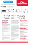
INVERTER
AIR TO WATER HEAT PUMPS
GSH-120IRAB-3 + GSH-120ERAB-3
GSH-140IRAB-3 + GSH-140ERAB-3
GSH-160IRAB-3 + GSH-160ERAB-3
Notices
Do not install the control where it is damp or exposed to direct sunlight.
Once the air conditioning unit is installed where possibly subject to electromagnetic interference,
shielded twisted pairs should be used as signal lines and other communication lines.
Be sure communication lines are wired to the correct ports, or normal communication would fail.
Do not beat, toss or frequently assemble and disassemble this control.
Do not operate the control with wet hands!
Figures in this Manual are just for reference!
We the manufacturers keep the right to modify this Manual owing to sales or other production
reasons without previous notice.
Contents
1. External View ...................................................................................... 1
1.1 Standby Page and Homepage ............................................................................ 2
1.2 Keys .................................................................................................................... 2
1.3 Indicating LEDs ................................................................................................... 3
2. Operation Instructions .......................................................................... 3
2.1 On/Off .................................................................................................................. 3
2.2 Function Setting .................................................................................................. 3
2.3 Parameter Setting (Parameter Set) .................................................................. 16
2.4 View .................................................................................................................. 18
2.5 General Set ....................................................................................................... 22
2.6 Key Lock ........................................................................................................... 23
3. Precautions ........................................................................................ 23
Air-to-water Heat Pump Wired Controller
1. External View
NO.
Symbol
Description
NO .
Symbol
Description
Running indicating LED
ON/OFFF
Power indicating LED
Cancel/Return key
Error indicating LED
OK key
Left key
Function key no. 4
Up key
Function key no. 3
Menu key
Function key no. 2
Right key
Function key no. 1
Down key
1
Air-to-water Heat Pump Wired Controller
1.1 Standby Page and Homepage
No.
item
Functional Description
1
Mode
2
Auxiliary Func.
3
Error state
It indicates if there is any error.
4
T-water out
It indicates the actual leaving water temperature.
5
T-outdoor
It indicates the actual outdoor environment temperature.
6
Key lock
It indicates if the key lock is activated or deactivated.
It is intended to access to the actual running mode.
It indicates the auxiliary function note 1.
Note:
it includes the “Sanitize mode”, “Quiet” mode, “Auto” mode, “Floor debug” mode, “Emergen.
mode”, “Holiday mode”, “Forced Cooling” mode, “Forced Heating” mode, and “Debug” mode.
1.2 Keys
No.
Item
Functional Description
1
ON/OFF key
2
OK key
3
Cancel/Return key
4
Menu key
5
Left/Right key
It is intended to move the cursor Left/Right.
6
Up/Down key
It is intended to modify the setting state or value of the selected parameter.
7
Function keys (4)
It is intended to turn on or off the unit.
It is intended to save the setting or go to the submenu.
It is intended to go to the higher level menu.
It is intended to call out the main menu or back to the homepage.
It is intended to perform different functions at difference pages.
2
Air-to-water Heat Pump Wired Controller
1.3 Indicating LEDs
NO.
Item
1
2
3
On/Off indicating LED (green)
Power indicating LED (yellow)
Fault indicating LED (red)
Functional Description
It will light on/off when the unit is turned on/off.
It will light on/off when the unit is powered on/off.
It will light on when some fault occurs.
2. Operation Instructions
2.1 On/Off
★ At the homepage, by pressing the ON/OFF key, the unit will be turned on/off.
★ When the unit is ON, the green indicating LED located at the upper right of the control will
light on. When the unit is OFF, the green indicating LED will light off.
[Notes]
•The unit is defaulted to be OFF when energized for the first time.
•The ON/OFF key operation works only at the home page and the standby page.
•When the “Holiday mode” or the “Emergen.mode” is activated, the ON/OFF key operation will
become ineffective.
•When the “Forced Heating” or “Forced Cooling” is activated, it will be deactivated by pressing
the “ON/OFF” key, and then press the ON/OFF key again to start the unit.
★ ON/OFF operation will be memorized by setting “Memory” to be “On” at the “GEN.” setting
page. That is, in case of power failure the unit will resume running upon power recovery. Once
“Memory” is set to be “Off”, in case of power failure the unit will keep “Off” upon power recovery.
•At the home page, the ON/OFF key is intended to turn on/off the unit if applicable. The Function
keys no.1 to no.4 are corresponding to “FUNC.”, “PAPA ”, “VIEW” and “GEN.” setting pages
respectively.
•At the standby page, the Menu key is used to back to the homepage, the ON/OFF key is used
to turn on/off the unit if applicable, and all other key operations are ineffective.
•The control will return automatically to the homepage where there is no any key operation in 10
consecutive minutes.
2.2 Function Setting
★1. At the homepage, by pressing the Function key no. 1, the control will access to the
FUNCTION page 1, as shown in the figure below.
★2. At the FUNCTION page, by the Right/Left key, the desired function option can be selected,
and by the Up/Down key, the setting of the current function option can be modified. The function key
no. 3 or no. 4 can be used for switch pages. After the setting is finished, by pressing the Menu
3
Air-to-water Heat Pump Wired Controller
key, the control will back to the homepage, or by pressing the Return key the control will back to the
higher level menu.
[Notes]
Move the cursor to the desired option and "Enter” will be displayed at the lower left side of the
LCD, reminding you that you are allowed to access to the submenu by pressing the OK key.
At the FUNCTION page, when the setting of some function option is changed and needs to be
memorized, then in case of power failure it will be saved automatically and resume upon power
recovery.
Function Settings
Displayed
Name
Range
Default
Remarks
1
Running mode
setting
Mode
Cool/Heat/ Hot
water/ Cool+Hot
water/ Heat+Hot
water
Heat
W he n t he w a ter t a nk is
unavailable, then only “Cool” and
“Heat” are included in the range.
2
Control state
Ctrl. state
T-water out / Troom
NO.
Full Name
3
Fast hot water
“T-Room” is available on ly when
T-water out “Remote Sensor” is set to “With”.
Fast hot water
On/Off
Off
W he n t he w a ter t a nk is
unavailable, this function will be
reserved, and the LCD will
display ‘Reserved’.
/
T-water ctrl.
High temp. /Low
temp.
Low temp.
5
Water out
temperature
control
Cool+hot water
Cool+hot water
Cool/Hot water
Cool
6
Heat+hot water
Heat+hot water
Heat/Hot water
Heat
W he n t he w a ter t a nk is
unavailable, this function will be
reserved, and the LCD will
display ‘Reserved’.
7
Quiet mode
Quiet mode
On/Off
Off
/
8
Quiet timer
Quiet timer
On/Off
Off
/
9
Auto mode
Auto mode
On/Off
Off
/
10
Holidayrelease
Holidayrelease
On/Off
Off
/
4
11
Sanitize
Sanitize
On/Off
Off
W he n t he w a ter t a nk is
unavailable, this function will be
reserved, and the LCD will
display ‘Reserved’.
12
Weekly timer
Weekly timer
On/Off
Off
/
13
Clock timer
On/Off
Off
/
Temp. timer
On/Off
Off
/
Floor debug
On/Off
Off
/
Emergen. mode
On/Off
Off
/
17
Clock timer
Temperature
timer
Floor debug
Emergency
mode
Holiday mode
Holiday mode
On/Off
Off
/
18
Thermostat
Thermostat
With/Without
Without
/
19
IDU heater
IDU heater
1/2/Off
1
/
20
Other heater
Other heater
With/Without
Without
/
21
Chassis heater
Chassis heater
On/Off
On/
/
22
Water tank
Water tank
With/Without
Without
23
Tank sensor
Tank sensor
1/2
2
/
W he n t he w a ter t a nk is
unavailable, this function will be
reserved,and the LCD will display
‘Reserved’ .
14
15
16
4
Air-to-water Heat Pump Wired Controller
24
25
Solar heater
FCU
Solar heater
FCU
With/Without
With/Without
Without
Without
26
Remote sensor
Remote sensor
With/Without
Without
27
Air removal
Air removal
On/Off
Off
/
/
When it is set to “Without”, the
“Co nt ro l s t at e” w i l l be
au t om at ic a l ly c h an g ed to
“T-water out”.
/
28
Address
Address
[0~125]
[127~253]
0
/
29
Doorguard
Doorguard
On/Off
Off
/
2.2.1 Mode
★ At the equipment OFF state, access to the FUNCTION page and then move through the Left/
Right key the cursor to the “Mode” whose characters will be reversed, then press the Up/Down key to
modify its setting.
[Notes]
•The “Heat” mode is defaulted when the unit is energized for the first time.
•The running mode is allowed to be changed only when the unit is not in operation. If it is done
with the unit being on, a window will pop up, warning “please turn off the system first”.
•When the water tank is disabled, only the ‘Heat” or the “Cool” mode is allowed.
•When the water tank is enabled, “Cool”, “Heat”, “Hot water”, “Cool+hot waterr”, “Heat+hot
water” is allowed.
★ For the heat pump, the “Cool” mode is allowed; for the heating only unit, “Cool+ Hot water”
and “Cool” are unallowable.
•This setting can be memorized upon power failure.
2.2.2 Control State (Ctrl. state)
★ Go to the FUNCTION page and locate Ctrl. state, then, configure it through the Up/Down key.
[Notes]
★ If “Remote sensor” is set to “With”, “T-out water” and “T-room” are available. While if “Remote
Sensor” is set to “Without”, only “T-out water” is selectable.
•This setting will be memorized upon power failure.
2.2.3 Fast Hot Water
★ Go to the FUNCTION page and locate “Fast hot water”, then, configure it through the Up/
Down key, “On” or “Off”.
[Notes]
★ It works only when “Water tank” is set to “With”.
•This setting will be memorized upon power failure.
2.2.4 T-water Ctrl (Water Temperature Control for Heating)
★ Go to the FUNCTION page and locate “T-water Ctrl.”, then, configure it through the Up/Down
key, “High temp.” or “Low temp.”.
[Notes]
•When this setting is changed, the following parameters will return to the default values.
Water out temperature for heating
WOT-Heat
Upper limit water-out temperature at the auto mode for heating
Upper WT-Heat
Lower limit water-out temperature at the auto mode for heating
Lower WT-Heat
•This setting will be memorized upon power failure.
5
45°C/113°F[High]
35°C/95°F[Low]
48°C/118°F[High]
35°C/95°F[Low]
40°C/104°F[High]
29C/84F[Low]
Air-to-water Heat Pump Wired Controller
2.2.5 Cool + Hot water
• Go to the FUNCTION page and locate “Cool+hot water”, then, configure it through the Up/
Down key, “Cool” or “Hot water”.
[Notes]
• "Hot water” will take precedence only when “Water tank” is available, other it will tell
“Reserved”.
•This setting will be memorized upon power failure.
2.2.6 Heat + Hot water
• Go to the FUNCTION page and locate Heat+hot water, then, configure it through the Up/
Down key, “Heat” or “Hot water”.
[Notes]
• "Hot water” will take precedence only when “Water tank” is available, other it will tell
“Reserved”.
•This setting will be memorized upon power failure.
2.2.7 Quiet Mode
• Go to the FUNCTION page and locate “Quiet mode”, then, configure it through the Up/Down
key, “On” or “Off”.
[Notes]
• It can be set to "On” or “Off” no matter if the unit is in operation or not.
•Once it is activated, it should be deactivated manually or by Quiet Timer.
• It will not memorized and defaulted to be off upon power failure.
• It will be deactivated when the unit is turned off.
2.2.8 Quiet Timer
★1 Go to the FUNCTION page and locate Quiet timer, then, access to the QUIET TIMER setting
page.
★2 At the QUIET TIMER setting page, select “Start time” or “End time” through the Left/Right
keys and then configure the desired time through the Up/Down keys.
★3 When the mode setting is finished, then by pressing "Save”, a pop-up window will pop up to
remind if you are determined to save this setting. If so, press the “OK” key. If not, press the “Cancel”
key to not save this setting.
★4. When the setting is saved, the control then will back to the FUNCTION page and the cursor
will be where the “Quiet timer” option is, then by the Up/Down kev it can be set to be “On” or “Off”.
6
Air-to-water Heat Pump Wired Controller
[Notes]
•Once it is activated, it should be deactivated manually.
• It will not be memorized and be defaulted to be off upon power failure.
•The saved “Start time” and “End time” will be memorized upon power failure.
• It is configurable no matter if the unit is in operation or not.
2.2.9 Auto Mode
• Go to the FUNCTION page and locate Auto mode, then, configure it through the Up/Down
key, “On” or “Off”.
[Notes]
•Once it is activated, it should be deactivated manually.
• It will be defaulted to be off upon power failure.
•At the “Parameter View” page, it is able to check the set point at the Auto mode.
•When it is activated, it is allowed to set the room temperature but the set point does not take
effective. However, when it is deactivated, the unit will run according to this set point.
• It can be set to “On” or “Off” no matter if the unit is in operation or not, but be activated only
when the unit is in operation.
• This mode works only for the air conditioning function.
2.2.10 Holiday Release
• Go to the FUNCTION page and locate “Holiday release”, then, configure it through the Up/
Down key, “On” or “Off”.
[Notes]
•When it is activated, at the WEEKLY TIMER page, it is able to set some week day to “Holiday
release”. In this case, the “Weekly timer” in this day is ineffective unless it is set to “Effective”
manually.
•This setting will be memorized upon power failure.
2.2.11 Sanitize
★1 At the FUNCTION page, locate “Sanitize”, and then access to the SANITIZE setting page by
pressing the OK key.
★2 At the SANITIZE setting page, select “Set clock”, “Set week” or “Set temp” through the Left/
Right key and then modify the corresponding setting through the Up/Down key.
★3 When the mode setting is finished, then by pressing “Save”, a pop-up window will pop up to
remind if you are determined to save this setting. If so, press the OK key. If not, press the Cancel key
to not save this setting.
★4 When the setting is saved, the control then will back to the FUNCTION page and the cursor
will be where the “Sanitize timer” is, then by the Up/Down key, it can be set to “On” or “Off”.
7
Air-to-water Heat Pump Wired Controller
[Notes]
• It can be activated only when the “Water tank” is set to “With”.
• It can be set to “On” or “Off” no matter if the unit is in operation or not
•When “Sanitize” is set to “On”, if you intend to set the “Emergen. mode”, “Holiday mode”, “Floor
Debug”, then a window will pop up, warning “Please disable the Sanitize Mode!”.
• It can be set to “On” or “Off” no matter if the unit is in operation or not, and “Hot water” mode
always takes precedence.
•When Sanitize is activated, “Sanitize” will show on the home page of the control until this
operation is finished. If this operation fails, “Sanitize fails” will show. In this case, by pressing any key,
“Sanitize failure” will be cleared or it will be always there.
•When Sanitize is activated, it will quit upon “Communication error with the indoor unit” or “Water
tank heater error”.
2.2.12 Weekly Timer
★1 At the homepage, by pressing the Function key access to the FUNCTION page, and then
locate where “Weekly timer” is by switching pages, after that, press OK key to go to the WEEKLY
TIMER setting page.
★2 At the WEEKLY TIMER setting page, by the Right/Left key it is able to select the desired
week day and then by the Up/Down key to set this day, “V”, “*” or “Holiday”, as shown in the figure
below. When this setting is finished, press OK key to go to this day’s setting page.
★3 At the week day’s setting page, it is allowed to set the running mode (Mode), temperature set
point (WT-HEAT), and water tank temperature (T-Water Tank). The running mode includes “Heat”,
“Cool”, “Hot water”, “Heat+ hot water”, “Cool+ hot water” (the last three ones are available only when
“Water tank” is set to “With”. There are totally five periods for each day, and each period can be set to
“V”or “*”. Besides, it is able to set the “Start time” and “End time” for each period, as shown in the
figure below.
8
Air-to-water Heat Pump Wired Controller
★4 When above settings are finished, pressing the Return key and then pressing “Save”, a popup window will pop up to remind if you are determined to save these settings. If so, press the OK key.
If not, press the Return key to not save these settings.
★5 In this case, finally by pressing the Up key, “Weekly timer” will be activated.
[Notes]
•Totally five periods are allowed to be set for each time. For each period, “Start time” must be
earlier than “End time”. Similarly, the preceding period must be earlier than its following period.
•When “Weekly timer” has been set successfully, by changing “FCU”, “Water tank”, “Ctrl state”,
or “T-water Ctrl”, then the temperature set point for “Weekly timer” will be automatically changed to
the set point of last setting. For instance, if “Heat” is set for Monday of “Weekly timer”, “FCU” is set to
“With” and the “T-water out” is 20°C, by resetting “FCU” to “Without”, then “T-water out” will be the
value of last setting. In this case, if FCU is disabled for last setting, then “T-water out” will be the
default value (18°C).
•At the “WEEKLY TIMER” setting page there are totally three setting types for each day
“V”: it indicates once the Week Timer is activated, the timer on this day is effective and will not
be affected by the “Holiday” mode.
“x”: it indicates even if the Week Timer is activated, the timer on this day is ineffective.
“Holiday”: it indicates when the Week Timer is activated but “Holiday” is not activated, then the
timer on this day is effective; when “Holiday” is also activated, the timer on this day is ineffective.
•When “Weekly timer” has already been set and the concerned modes include “Hot water”, if
resetting “Water tank” from “With” to “Without”, then “Hot water” mode will be automatically changed
to “Heat”, “Cool+hot water”/ “Heat+hot water” changed to “Cool”/ “Heat”.
•Temperature Setpoint
The control is able to decide the temperature type and temperature range based on the current
“Clock Timer”, “FCU”, “T-water Ctrl.”, and “Ctrl. state” settings. See the followings for more details.
9
Air-to-water Heat Pump Wired Controller
If the set mode is “Hot water”, the temperature set point shows nothing, indicating there is no
need to set “T-water out” and “T-room” but only “T- tank”. If the set mode “Cool” or “Heat”, then water
tank temperature box will show nothing, indicating there is no need to set “T-tank”.
Ctrl.
state
Set
Mode
Object
Range
Default
Accuracy
18-25 °C
(Without
FCU)
7 °C (With FCU) 18 °C
(Without FCU)
1 °C
High temp.
25-55 °C
45 °C
1 °C
Low temp.
25-45 °C
35 °C
1 °C
Cool
Water out
7-25 °C (With
temperature for
FCU)
cooling(WT-cool)
Heat
Water out
temperature for
heating(WT-heat)
T-water
out
Cool
Room
temperature for
cooling(RT-cool)
18-30 °C
20 °C
1 °C
Heat
Room
temperature for
heating(RT-heat)
18-30 °C
26 °C
1 °C
T-room
2.2.13 Clock Timer
★1 At the homepage, by pressing the Function no.1 key access to the FUNCTION page, and then
locate where “Clock timer” is, after that, press OK key to go to the COLCK TIMER setting page.
★2 At the CLOCK TIMER setting page, by the Left/Right key select the desired parameter and
then by the Up/Down key configure it.
★3 When this setting is concerned about time value, by pressing the Function key no. 1
alternately set the hour or minute values, and by pressing the Up/Down key increase or decrease the
corresponding value which will be continuously changed by pressing and holding the key.
(Unless otherwise specified, all timer settings follow the similar way.)
★4When the setting is finished, save it by pressing the Function key no. 2, or this setting without
being saved is ineffective.
★5 When the setting has been saved, activate the “Clock Timer” at the FUNCTION page.
[Notes]
•When “Weekly timer” and “Clock timer” settings are performed at the same time, the latter takes
precedence.
•When the water tank is available, the allowed running modes include “Heat”, “Cool”, “Heat+
10
Air-to-water Heat Pump Wired Controller
hot water”, “Cool+hot water”, and “Hot water”.
When the water tank is unavailable, the allowed running modes only include “Heat” and “Cool”.
•When “Clock timer” has already been set and the concerned modes include “Hot water”, if
resetting “Water tank” from “With” to “Without”, then “Hot water” mode will be automatically changed
to “Heat”, “Cool+hot water”/ “Heat+hot water” changed to “Cool”/ “Heat”.
Full Name
Displayed Name
Range
Default
Set Mode
Mode
Cool/
Heat/
Hot water/ Cool+hot
water/ Heat+hot water
Heat
Water out temperature for cooling /
Room temperature for cooling / Water
out temperature for heating / Room
temperature for heating
WT-heat/
RT-heat/
WT-cool/
RT-cool
Refer to the
temperature setting
range of “Weekly
Timer”.
35°C
Tank temperature
T-water tank
40~80°C/104~176°F
50°C/122°F
Start time
Start time
00:00-23:59
08:30
End time
End time
00:00-23:59
17:30
2.2.14 Temp. Timer
★1 At the homepage, by pressing the Function key access to the FUNCTION page, and then
locate where “Temp timer” is, after that, press OK key to go to the TEMP TIMER setting page.
★2 At the TEMP TIMER setting page, by the Left/Right key select the desired parameter and
then by the Up/Down key configure it. The configurable parameters include “Mode”, “Period 1”, “WTHEAT 1”, “Period 2” and “WT-HEAT 2”.
★4 When the setting is finished, save it by pressing the Function key no. 2, or this setting without
being saved is ineffective.
★5 When the setting has been saved, activate the “Temp. timer” at the FUNCTION page.
[Notes]
• When “Weekly timer”, “Clock timer”, and “Temp. timer” settings are performed at the same
time, the last one takes precedence.
• This function works only when the unit is in operation.
• The allowed running modes include “Heat” and “Cool”
• When the start time of “Period 2” is equal to that of “Period 1”, then the set point of “Period 2”
takes precedence.
• TEMP. TIMER is judged by the timer value.
11
Step
Air-to-water Heat Pump Wired Controller
• During the setting, the temperature set point which is set manually always takes precedence.
Full Name
Displayed Name
Range
Default
Set Mode
Mode
Cool/Heat
Heat
Period 1 running time
Period 1
00:00-23:59
08:30
Water out temperature for cooling /
Room temperature for cooling / Water
out temperature for heating / Room
temperature for heating
WT-heat 1/ RT-heat 1/
WT-cool 1/ RT-cool 1
Refer to the
temperature setting
range of “Weekly
Timer”.
35°C/95°F
Period 1 running time
Period 2
00:00-23:59
17:30
Water out temperature for cooling /
Room temperature for cooling / Water
out temperature for heating / Room
temperature for heating
WT-heat 2/ RT-heat 2/
WT-cool 2/ RT-cool 2
Refer to the
temperature setting
range of “Weekly
Timer”.
35°C/95°F
2.2.15 Floor Debug
★1 At the homepage, by pressing the Function key access to the FUNCTION page, and then
locate where “Floor debug” is, after that, press OK key to go to the FLOOR DEBUG setting page.
★2 At the FLOOR DEBUG setting page, by the Left/Right key select the desired parameter and
then by the Up/Down key configure it. The configurable parameters include “Segments”, “Period 1
temp”, “AT of segment”, and “Segment time”, as listed in the following table..
NO.
Full Name
Displayed Name
Range
Default
Step
1
Segments for floor debug
Segments
1~10
1
1
Period 1 temp
25~35 °C/
77-95 °F
25 °C/77 °F
1 °C/1 °F
AT of segment
0~72H
0
12H
Segment time
2~10 °C/
36-50 °F
5 °C/41 °F
1 °C/1 °F
2 First temperature for floor debug
Segment temperature difference
for floor debug
Segments duration for floor
4
debug
3
★3 After the above setting is finished, by pressing the function key no. 2 activate this function
and a dialog box will pop up, reminding “Start the Floor Debug Mode now?”. If so, press the “OK” key.
Once “Floor debug” has been activated, by pressing the function key no. 2, a dialog box also will pop
up, reminding “Stop the Floor Debug Mode now?” If so, press the OK key; if not, press “Cancel” to go
on.
[Notes]
• This function can be activated only when the unit is OFF. When it is intended to activate this
12
Air-to-water Heat Pump Wired Controller
function with the unit being ON, a dialog box will pop up, warning “Please turn off the system first!”.
• When this function has been activated, it is unable to turn on or off the unit. In this case, when
pressing the ON/OFF key, a dialog will pop up, warning “Please disable the Floor Debug Model”.
• When this function has been set successfully, “Timer week”, “Clock timer” and “Temp timer”
will be deactivated.
• ’’When “Floor debug” mode has been activated, “Emergen.mode”, “Sanitize”, “Holiday mode”
is not allowed to be activated, or a dialog box will pop up, warning “Please disable the Floor Debug
Model”.
• Upon power failure, this function will be OFF and runtime will be cleared.
• At the FlOOR DEBUG setting page, the control will remain at this page and never back to the
homepage unless pressing the Return key or Menu key.
• When this function is activated, it is allowed to check the target temperature and runtime of
“Floor Debug” at the Parameter View page.
• Before activating “Floor debug”, please make sure each period for “Floor debug” is not zero, or
a dialog box will pop up, warning “Wrong Floor Debug time!”. It will resume only by pressing “OK” and
then correcting the time.
2.2.16 Emergency Mode (Emergen. Mode)
★1 Set “Mode” to “Heat” or “Hot water” at the Parameter Set page
★2 Then, switch pages to go the page where “Emergen. mode”, locate it by the Left/Right key,
and configure it to “On” or “Off” by the Up/Down key.
★3 When it is set to “On”, “Auxiliary func.” at the homepage will be replaced by “Emergen.
Mode”.
★4 When it is set to “On” but the running mode is not “Heat” or “Hot water”, a dialog will pop up,
warning “Wrong running model”. In this case, by pressing the OK key, the control will go to the Mode
setting page, or by pressing the Cancel key, the control will return to the “Emergen. Mode” page.
[Notes]
•When the unit is performing “Heat” at the Emergency mode, if there is water flow switch
protection, IDU assistant heater welding protection, or leaving water temperature sensor error, the
Emergency mode will quit and will not be allowed to be activated.
•When the unit is performing “Hot water” at the Emergency mode, if there is water tank heater
welding protection, or water tank temperature sensor error, the Emergency mode will quit and will not
be allowed to be activated.
•At the Emergency mode, the ON/OFF key operation will be disabled; the running mode will not
be allowed to be changed; the Quiet and Auto modes cannot be deactivated; “Weekly timer”, “Clock
timer” and “Temp timer” also cannot be activated, or will be deactivated if being activated.
• At the Emergency mode, commands from the Thermostat is ineffective.
• At the Emergency mode, only one running mode between “Heat” and “Hot water” is allowed.
•This function can be activated only when the unit is OFF, or a dialog box will pop up, warning
“Please turn off the system first!”
• Under the Emergency mode, “Floor debug”, “Sanitize”, “Holiday mode”, cannot be activated,
or a dialog box will pop up, warning “ Please disable the Emergency Model”.
• Upon power failure, the “Emergen. mode” will be defaulted to be “Off”.
2.2.17 Holiday Mode
★1 Locate where “Holiday mode” at the FUNCTION page
★2 Set Holiday to “On” or “Off” by the Up/Down key.
13
Air-to-water Heat Pump Wired Controller
[Notes]
•At the holiday mode, “Mode” setting of the control and On/Off key operation both are disabled.
•When it is activated, “Weekly timer”, “Clock timer” or “Temp timer” will be deactivated.
•At the holiday mode, when “T-Room” is adopted, the temperature set point should be 15°C;
when “T-Out water” is adopted, then the temperature set point should be 30°C.
• It will quit when the thermostat effectively works (“Cool” or “OFF” operation).
• When this setting is saved successfully, it will be memorized upon power failure.
•This function can be activated only at the “Heat” mode and with the unit turned off. When it is
done with the unit turned on, a prompt dialog box will pop up, warning “ Please turn off the system
first!”; or when it is done at other modes except the “Heat” Mode with the unit turned off, also a prompt
dialog box will pop up, warning “Wrong running mode!”.
•When it is activated, the ON/OFF key operation is disabled, or a dialog box will pop up, warning
“Please disable the Holiday Mode !”.
• Under the Holiday mode, “Floor debug”, “Sanitize”, “Emergen. mode” cannot be activated, or
a dialog box will pop up, warning “Please disable the Holiday Mode !”.
2.2.18 Thermostat
★1 Locate where “Thermostat” is at the FUNCTION page
★2 By pressing the Up/Down key, Thermostat can be set to “On” or “Off”. When it is “On”, the
control follows the running mode of the thermostat and is not allowed to set the running mode; when it
is “Off”, the control follows the running mode set by itself.
[Notes]
• When “Floor debug” or “Emergen. Mode” is activated, then the control will not receive signals
from the thermostat.
• If “Thermostat” is set to “On”, the control will automatically disable some functions concerning
timer, and run in accordance with the mode set by the thermostat. In this case, the running mode is
unchangeable and the ON/OFF key operation of the control is ineffective.
• When this setting is saved successfully, it will be memorized upon power failure.
• The state of the Thermostat can be changed when the unit is turned off.
2.2.19 IDU Heater
• Go to the FUNCTION page and locate “IDU Heater”, then, configure it through the Up/Down
key, “1” , "2" or “Off”.
[Notes]
•it will be memorized upon power failure.
2.2.20 Other Heater
• Go to the FUNCTION page and locate Other heater, then, configure it through the Up/Down
key, “With” or “Without”.
[Notes]
•it will be memorized upon power failure.
2.2.21Chassis Heater
• Go to the FUNCTION page and locate “Chassis Heater” then, configure it through the Up/
Down key, “With” or “Without”.
[Notes]
•it will be memorized upon power failure.
14
★
Air-to-water Heat Pump Wired Controller
2.2.22 Water Tank
★ Go to the FUNCTION page and locate “Water tank” then, configure it through the Up/Down
key, “With” or “Without”.
[Notes]
•it will be memorized upon power failure.
★ This setting is allowed only when the unit is turned off.
2.2.23 Tank Sensor
★ Go to the FUNCTION page and locate “Water tank”, then, configure it through the Up/Down
key, “1” or “2”. When the water tank is unavailable, this option will be reserved.
[Notes]
•it will be memorized upon power failure.
2.2.24 Solar Heater
★ Go to the FUNCTION page and locate “Solar heater”, then, configure it through the Up/Down
key, “With” or “Without”.
[Notes]
•it will be memorized upon power failure.
2.2.25 FCU
★ Go to the FUNCTION page and locate “FCU”, then, configure it through the Up/Down key,
“With” or “Without”.
[Notes]
★ It will be memorized upon power failure.
2.2.26 Remote Sensor
★ Go to the FUNCTION page and locate “Remote sensor”, then, configure it through the Up/
Down key, “With” or “Without”.
[Notes]
•it will be memorized upon power failure.
★ "T-room Ctrl” can be selected only when the Remote Sensor is set to “With”.
2.2.27 Air removal
★ Go to the FUNCTION page and locate “Air removal”, then, configure it through the Up/Down
key, “On” or “Off”.
[Notes]
•it will not be memorized upon power failure.
★ It can be set only when the unit is turned off.
2.2.28 Address
★ Go to the FUNCTION page and locate “Address”, then, configure it through the Up/Down key
to set the address.
[Notes]
★ It indicates the address of the control and is intended for the group control.
★ It will be memorized upon power failure.
★ The address range is [0,125] and [127,253]
★ The default address is 0 for the initial use.
2.2.29 Doorguard
★ Go to the FUNCTION page and locate “Doorguard”, then, configure it through the Up/Down
15
Air-to-water Heat Pump Wired Controller
key, “On” or “Off”.
[Notes]
• When it is activated, the control will check the card is inserted or not. If inserted, the control will
run normally; if not, the control will turn off the unit and back to the homepage. In this case, any key
operation is ineffective (except for the combined key operation), or a dialogue box will pop up,
warning “Keycard uninserted!”.
•it will not be memorized upon power failure.
2.3 Parameter Setting (Parameter Set)
2.3.1 User Parameter Setting
★1 At the homepage, it is able to go to the PARAMETER page by pressing the Function key
no.2.
★2 At the Parameter Set page, by the Left/Right key select the desired option and then by the
Up/Down key increase or decrease the setting value which will be continuously changed when
pressing and holding the key.
★3 When the setting is finished, press "Save” and a dialog box will pop up, reminding “Save
settings?”. If so, press the OK key; if not press the Cancel key to not save this setting.
16
Air-to-water Heat Pump Wired Controller
NO.
Full Name
Displayed
Name
Range (°C)
Range(°F)
Default
1
Water out temperature for
cooling
WOT-Cool
7~25 °C [With FCU] 18~25
°C [Without FCU]
45~77 °F [With FCU]
64~77 °F [Without FCU]
18 °C /64 °F [Without FCU]
2
Water out temperature for
heating
WOT-Heat
25~55 °C [High temp.]
25~45 °C [Low temp.]
77~131 °F [High temp.]
77~113 °F [Low temp.]
45 °C /113 °F [High temp.]
35 °C /95 °F [Low temp.]
RT-Cool
18~30 °C
64~86 °F
20 °C /68 °F
RT-Heat
18~30 °C
64~86 °F
26 °C /79 °F
3
4
Room temperature for
cooling
Room temperature for
heating
7 °C /45 °F [With FCU]
5
Tank temperature
T-water tank
40~80 °C
104~176 °F
50 °C /122 °F
6
Eheater-on ambient
temperature
T-Eheater
-20~18 °C
-4~64 °F
0 °C /32 °F
7
Extra-heater-on ambient
temperature
T-Extraheater
-20~18 °C
-4~64 °F
0 °C /32 °F
8
Max heat pump waterout
temperature (no eheater)
T-HP Max
40~50 °C
104~122 °F
50 °C /122 °F
9
Lower limit ambient
temperature at the auto
mode for heating
Lower AT-Heat
-20~5 °C
-4~41 °F
-15 °C /5 °F
10
Upper limit temperature at
the auto mode for heating
Upper AT-Heat
10~20 °C
50~68 °F
15 °C /59 °F
11
Upper limit room
temperature at the auto
mode for heating
Upper RT-Heat
22~30 °C
72~86 °F
24 °C /75 °F
Lower RT-Heat
18~21 °C
64~70 °F
20 °C /68 °F
Upper WT-Heat
46~55 °C [High temp.]
30~35 °C [Low temp.]
115~131 °F [High temp.]
86~95 °F [Low temp.]
48 °C /118 °F [High temp.] 35
°C /95 °F [Low temp.]
12
13
Lower limit room
temperature at the auto
mode for heating
Upper limit water-out
temperature at the auto
mode for heating
14
Lower limit water-out
temperature at the auto
mode for heating
Lower WT-Heat
36~45 °C [High temp.]
25~29 °C [Low temp.]
97~113 °F [High temp.]
77~84 °F [Low temp.]
40 °C /104 °F [High temp.] 29
°C /84 °F [Low temp.]
15
Lower limit ambient
temperature at the auto
mode for cooling
Lower AT-Cool
10~25 °C
50~77 °F
25 °C /77 °F
16
Upper limit temperature at
the auto mode for cooling
Upper AT-Cool
26~48 °C
79~118 °F
40 °C /104 °F
17
Upper limit room
temperature at the auto
mode for cooling
Upper RT-Cool
24~30 °C
75~86 °F
27 °C /81 °F
18
Lower limit room
temperature at the auto
mode for cooling
Lower RT-Cool
18~23 °C
64~73 °F
22 °C /72 °F
19
Upper limit water-out
temperature at the auto
mode for cooling
Upper WT-Cool
15~25 °C [With FCU]
22~25 °C [Without FCU]
59~77 °F [With FCU] 72~77
°F [Without FCU]
15 °C /59 °F [With FCU]
23 °C /73 °F [Without FCU]
7~14 °C [With FCU]
18~21 °C [Without FCU]
45~57 °F [With FCU]
64~70 °F [Without FCU]
18 °C /64 °F [Without FCU]
2~10 °C
36~50 °F
5 °C /41 °F
2~10 °C
36~50 °F
10 °C /50 °F
2~8 °C
36~46 °F
5 °C /41 °F
Lower limit water-out
Lower WT-Cool
temperature at the auto
mode for cooling
Temperature deviation for
21
△T-Cool
cooling
Temperature deviation for
22
△T-Heat
heatling
23 Temperature deviation for
△T-hot water
heating water
20
17
7 °C /45 °F [With FCU]
Air-to-water Heat Pump Wired Controller
2.4 View
★1 At the homepage, by pressing the Function key no.3 it is able to go to the VIEW page as shown
in the figure below.
2.4.1 Status View
★1 At the VIEW page, select “Status” and then press the OK key to go to the STATUS
page. ★2 At the STATUS page, it is able to check the status of each component.
Viewable Components
Full Name
Displayed Name
Status
Compressor running state
Compressor
On/Off
Fan 1 running state
Fan 1
On/Off
Fan 2 running state
Fan 2
On/Off
IDU water pump running state
IDU-WP
On/Off
Solar water pump running state
Solar-WP
On/Off
Tank heater running state
Tank heater
On/Off
3-Way valve running state
3-way valve
On/Off
Crankcase heater running state
Crankc.heater
On/Off
Chassis heater running state
Chassis heater
On/Off
Defrost
Defrost
On/Off
Oil return
Oil return
On/Off
Thermostat
Thermostat
On/Off
Assistant heater running state
Assist. heater
On/Off
Water switch running state
Water switch
On/Off
18
Air-to-water Heat Pump Wired Controller
Circulating two-way valve 1 running state
CTW-valve 1
On/Off
Circulating two-way valve 2 running state
CTW-valve 2
On/Off
Doorguard
Doorguard
Card in/Card out
Opration LED
Opration LED
On/Off
Error LED
Error LED
On/Off
4-way valve running state
4-way valve
On/Off
IDU heater 1 running state
IDU heater 1
On/Off
IDU heater 2 running state
IDU heater 2
On/Off
Auto-antifreeze
Auto-antifree.
Enabled/Disabled
2.4.2 Parameter View (Para View)
★1 At the VIEW page, select Parameter and then press the OK key to go to the Para View page.
★2 At the Para View page, it is able to view each parameter.
NO.
Full Name
Displayed Name
1
Outdoor temperature
T-outdoor
2
Suction temperature
T-suction
3
Discharge temperature
T-discharge
4
Defrost temperature
T-defrost
5
Liquid temperature
T-liquid
6
Water in temperature
T-water in
7
Plate exchanger water-out temperature
T-waterout PE
8
E-heater water-out temperature
T-waterout EH
9
Water tank temperature set point
T-tank ctrl.
10
Water tank temperature reading
T-tank display
11
Remote room temperature
T-remote room
12
Refrigerant-side gas pipe temperature
T-RGP
13
Solor heater water-out temperature
T-SHW
14
Target temperature for auto mode
T-auto mode
15
Target temperature for floor debug
T-floor debug
16
Time period for floor debug
Debug time
19
Status
Exact values
Air-to-water Heat Pump Wired Controller
2.4.3 Error View
★1 At the VIEW page, select Error and then press the OK key to go to the ERROR page. ★2 At the
Error View page, it is able to view each error.
[Notes]
•The real-time error will show on the control. Taking Error 2 in the above figure for example,
when it is recovered, it will disappear and be replaced by Error 3, and other errors follow the same
way.
• If the total no. of errors exceed six, other errors should be viewed by switching pages through
“Last” and “Next”.
•
Any one among “IDU auxiliary heater 1 error”, “IDU auxiliary heater 2 error”, “Water tank
heater error” occurs, the control will beep until this error has been cleared.
• See the following table for error description.
Full Name
Displayed Name
Error Code
Ambient temperature sensor error
Ambient sensor
F4
Condenser temperature sensor error
Cond.sensor
F6
Discharge temperature sensor error
Disch. sensor
F7
Suction temperature sensor error
Suction sensor
F5
Outdoor fan error
Outdoor fan
EF
Compressor internal overload protection
Comp. overload
H3
High pressure protection
High pressure
E1
Low pressure protection
Low pressure
E3
High discharge protection
Hi-discharge
E4
Incorrect capacity DIP switch setting
Capacity DIP
c5
Communication error between indoor and outdoor unit
ODU-IDU Com.
E6
High pressure sensor error
Pressure sens.
FC
Heat exchanger-leaving water temperature sensor error
Temp-HELW
F9
Auxiliary heater-leaving water temperature sensor error
Temp-AHLW
dH
Refrigerant liquid line temperature sensor error
Temp-RLL
F1
Heat exchanger-entering water temperature sensor error
Temp-HEEW
/
Water tank water temperature sensor 1 error
Tank sens. 1
FE
Water tank water temperature sensor 2 error
Tank sens. 2
/
Refrigerant gas line temperature sensor error
Temp-RGL
Solar heater-leaving water temperature sensor error
Temp-SHLW
Room temperature sensor error
Sensor-RT
20
F3
/
F0
Air-to-water Heat Pump Wired Controller
Water flow swich protection
WS-protection
EC
Welding protection of the auxiliary heater 1
Auxi. heater 1
EH
Welding protection of the auxiliary heater 2
Auxi. heater 2
EH
Welding protection of the water tank heater
Auxi. -WTH
EH
Under-voltage DC bus or voltage drop error
DC under-vol.
PL
Over-voltage DC bus
DC over-vol.
PH
AC current protection (input side)
AC curr. pro.
PA
IPM defective
IPM defective
H5
PFC defective
FPC defective
HC
Start failure
Start failure
LC
Phase loss
Phase loss
LD
Drive module resetting
Driver reset
P0
Compressor over-current
Com. over-curr.
P5
Overspeed
Overspeed
LF
Sensing circuit error or current sensor error
Current sen.
PC
desynchronizing
Desynchronize
H7
Compressor stalling
Comp. stalling
LE
Communication error
drive-main com.
P6
Radiator or IPM or PFC module overtemperature
Overtemp.-mod.
P8
Radiator or IPM or PFC module temperature sensor error
T-mod. sensor
P7
Charging circuit error
Charge circuit
PU
Incorrect AC voltage input
AC voltage
PP
Drive board temperature sensor error
Temp-driver
PF
AC contactor protection or input zero crossing error
AC contactor
P9
Temperature drift protection
Temp. drift
PE
Current s ens or c o n nec t i on pr o tec t i on (current s ens or n ot
connected to phase U/V)
Sensor con.
PD
Communication error to the outdoor unit
ODU Com.
E6
Communication error to the indoor unit
IDU Com.
E6
Communication error to the drive
Driver Com.
E6
2.4.4 Version View (VERSION)
★1.At the VIEW page, select Version and then press the OK key to go to the VERSION page.
★1 At the VERSION page, the program and protocol versions are listed.
21
Air-to-water Heat Pump Wired Controller
2.5 General Set
★1. At the homepage, by pressing “GEN.” access to the GENERAL SET page. At this page, it is
able to set “Temp. unit”, “Language”, “On/off memory”, “Time & Date”, “Beeper” and “Back light”, as
shown in the figure below.
NO.
Full Name
Displayed Name
Range
Default
Remarks
1
Temperature unit
Temp. unit
Celsius/
Fahrenheit
Celsius
/
2
Language
Language
Chinese/English
English
/
3
On/off memory
On/off memory
On/Off
On
/
4
Time&Date
Time&Date
/
/
/
5
Beeper
Beeper
On/Off
On
/
Energy save
“Lighted” :
it always lights on.
“Eco”: it lights off
when there is no key
operation for 1
minute, and will
l ig h ts on w h er e
th er e is any k ey
operation.
6
Back light
Back light
Lighted/Energy
save
2.5.1 Clock Setting
★1 At the homepage, by pressing “GEN.” access to the GENERAL SET page. Then, select
“Time & Date” at this page. After that, go to the “Time & Date” setting page by pressing the OK key.
★ Change the set value by pressing the Up/Down key. Then by pressing “Save”, a pop-up
window will pop up to remind if you are determined to save this setting. If so, press the OK key. If
not, press the Cancel key to not save this setting. The saving setting will update at the upper left
corner of the control.
22
Air-to-water Heat Pump Wired Controller
2.6 Key Lock
★ At the homepage, by pressing the Up/Down keys simultaneously for 5 seconds, it is able to
activate or deactivate this function. When it is activated, any key operation is ineffective.
3. Precautions
Install the control following instruction shown in the figure below.
NO.
Name
1
LCD
2
Communication line
Installation Steps
Step 1: draw the communication lines out from the LCD
Step 2: take four screws away from the rubber pad.
Step 3: remove the rubber pad off the LCD.
23
3
Screws ST4.2X16
4
Rubber pad
Manufacturer:
Sinclair Corporation Ltd., 1-4 Argyll Street,
London W1F 7LD, UK
Supplier and technical support:
Nepa, spol.s.r.o.
Purky ova 45
612 00 Brno
Czech Republic
www.nepa.cz
Toll-free info line:
+420 800 100 285
Original manual