1
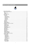
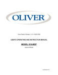
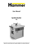
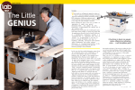
Grand Rapids, Michigan, U.S.A. 49504-5298
USER’S OPERATING AND INSTRUCTION MANUAL
MODEL 600-R3 SERIES
DOUGH MOULDERS
600-R3S20000-CV
THIS PAGE WAS INTENTIONALLY
LEFT BLANK.
GEN020319
SAFETY INSTRUCTIONS
Various safety devices and methods of guarding have been provided on this machine. It
is essential, however, that machine operators and maintenance personnel observe the
following safety precautions. Improper installation or operation of this equipment may
cause injury to personnel or damage to equipment.
1. Read this manual before attempting to operate your machine. Never allow an
untrained person to operate or service this machine.
2. Connect the machine to a properly grounded electrical supply that matches the
requirements shown on the electrical specification plate and follow specifications of
local electrical codes.
3. Disconnect and lock-out the machine from the power supply before cleaning or
servicing.
4. Check and secure all guards before starting the machine.
5. Observe all caution and warning labels affixed to the machine.
6. Use only proper replacement parts.
7. Do not wear loose fitting clothing or loose hair. Shirt tails should be tucked in.
8. Wear proper personal safety equipment.
9. Keep Hands away form the moving parts of this machine while it is in operation.
10. In addition to these general safety instructions, also follow the more specific safety
instructions given for the different areas of the machine in the operating instructions.
WARNING
DO NOT USE FOR OTHER THAN ORIGINALLY INTENDED PURPOSE
REV. 12-15-95
GEN951215
600-R3
MODEL 600-R3 SERIES DOUGH MOULDERS
INDEX
SECTION
PAGE N0.
1.0 DESCRIPTION/SPECIFICATIONS .............................................................. 1-1
1.1 Description
1.2 Dimensional Specifications
1.3 Electrical Specifications
1.4 Wiring Diagram
2.0 MACHINE INSTALLATION .......................................................................... 2-1
2.1 Electrical Requirements
2.2 Machine Running Direction
3.0 OPERATING INSTRUCTIONS .................................................................... 3-1
3.1 Machine Preparation
3.2 Establishing Settings
4.0 CLEANING/MAINTENANCE ....................................................................... 4-1
4.1 Cleaning
4.2 Changing the Felt Under the Heavy Mat
4.3 Changing the V-belt
4.4 Replacing the Motor
4.5 Removing Rear Chamber Assembly and Belt
4.6 Removing the Sheeting Rollers
4.6.1 Removing the Upper Sheeting Roller
4.6.2 Removing the Lower Sheeting Roller
4.7 Replacing the Front Triangular Belt
4.7.1 Removing the Front Triangular Belt
4.7.2 Installing the Front Triangular Belt
5.0 REPLACEMENT PARTS ............................................................................. 5-1
5.1 Assembly Drawings
5.2 Parts List
5.3 Recommended Spare Parts
WARRANTY ................................................................................................
WARRANTY PROCEDURE ………………………………………………….....
RETURNED PARTS POLICY ......................................................................
0600S20005.doc
Rev. 2/25/04
THIS PAGE WAS INTENTIONALLY
LEFT BLANK.
GEN020319
600-R3
MODEL 600-R3 SERIES DOUGH MOULDER
1.0
DESCRIPTION / SPECIFICATION
1.1
Description
The moulder stretches dough gently and gradually between two belts revolving in
opposite directions and at different speeds. The dough is inserted in a hopper located
approximately 54" from the floor (when mounted on the Oliver Moulder stand with
casters), which feeds it between three plastic coated sheeting rollers. The sheeting and
stretching operations are controlled manually with two levers with easy to read scales.
The moulded dough is delivered below the hopper on a felt covered retractable shelf
approximately 32" above the floor (when mounted on the Oliver Moulder stand with
casters).
All driving cylinders are mounted on sealed bearings which are lubricated at the factory
and need no further lubrication. The front belt rotates on three cylinders positioned in a
triangular pattern while the rear belt rotates in the opposite direction on two cylinders.
The three plastic coated sheeting rollers, (of which the lower one is adjustable), flatten
the dough after it is inserted in the hopper.
The moulder is driven by a 3/4 HP open drip proof motor which is easily adjustable for
tightening the V-belt drive. The revolving belts are driven by a noiseless gear belt
system which never needs lubrication.
1-1
0600S20006.doc
Rev. 5/02/02
600-R3
1.2
Dimensional Specifications
Product Capacities:
2 ounces (0.1kg) to 6 pounds (3.0kg)
Machine size:
Width = 43 inches
Height = 28 inches,
Height OA = 60 inches
Depth = 28-1/2 inches,
Depth OA = 37-1/4 inches
Net Weight:
Approximately 380 pounds
425 pounds with stand
Shipping Weight:
Approximately 575 pounds
1.3
Electrical Specifications
208-220/440 Volts AC
3 Phase, 50/60 Hz,
3/4 Horse Power
3.1-3.1/1.5 AMPS.
1.4
Wiring Diagram
1-2
0600S20006.doc
Rev. 5/02/02
2.0
2.1
600-R3
MODEL 600-R3 SERIES DOUGH MOULDER
MACHINE INSTALLATION
Electrical Requirements
First, check the wall receptacle to be sure it is a three phase, 230 volt receptacle. If not,
one must be installed. Attach a three phase, 230 volt plug to the end of the power cord.
Be sure the pattern of the wall receptacle and pattern of the plug are matching.
NOTE
A TWIST-LOCK TYPE PLUG MUST BE USED ON THE 600-R3 SERIES OF
DOUGH MOULDERS POWER CORD TO KEEP IN COMPLIANCE WITH
ETL SAFETY REQUIREMENTS.
Before putting machine into operation, check to see if the machine is running in the
correct direction. (See Section 2.2).
2.2
Machine Running Direction
To check for proper running direction you must first disengage the heavy mat, (Item
#808, Assembly Drawing 5.1.1) by removing the left and right heavy mat support springs
(Item #809, Not Shown) from their posts located towards the top. Lay the heavy mat
and under lying felt over the front of machine. Then switch the machine on briefly and
observe the direction in which the front triangular belt is moving. If the belt is moving
upward the belt rotation is correct. If the belt is moving downward the machine’s running
direction must be reversed. Unplug the machine from the power receptacle. Reverse
the black and white wires in the plug at the end of the power cord.
When the running direction of the machine is correct reinstall the heavy mat.
Proper Running Direction
2-1
0600S20007.doc
Rev. 5/2/02
600-R3 SERIES DOUGH MOULDER
3.0
OPERATING INSTRUCTIONS
3.1
Machine Preparation
Always flour the delivery outfeed table felt generously and thoroughly. You should also
flour the dough as thickly as possible, all around. Also, when preparing to run the
moulder we recommend that you first weigh as many pieces of dough as possible in
advance.
3.2
Establishing Settings
NOTE
ADJUSTMENTS SHOULD BE MADE WHILE THE MACHINE IS RUNNING.
Gently drop a piece of dough in the hopper and observe its shape after moulding.
•
•
•
•
•
•
If the loaf is too compact, open the sheeting rollers.
If the loaf is not compact enough, close the sheeting rollers.
If the loaf is too short, close the rear chamber.
If the loaf is too long, open the rear chamber.
If the loaf is too fat in the center, close the sheeting rollers while sheeting, or, the
dough may be too stiff.
If the ends twist, open the rear chamber.
We recommend that all settings be recorded for later use once they are established.
Remember, results may vary depending on dough condition. If required, make
adjustments gradually starting with the original established setting.
ESTABLISHED SETTINGS
FOR SHEETING ROLLERS & REAR CHAMBER OPENINGS
LOAF TYPE
_____________________________
SHEETING
______
STRETCHING
______
_____________________________
______
______
_____________________________
______
______
_____________________________
______
______
_____________________________
______
______
_____________________________
______
______
_____________________________
______
______
_____________________________
______
______
3-1
0600S20008.doc
Rev. 5/2/02
600-R3 SERIES DOUGH MOULDER
WARNING
ALWAYS MAKE SURE THE MACHINE HAS BEEN DISCONNECTED FROM THE
POWER SUPPLY BEFORE CLEANING OR SERVICING.
4.0
CLEANING / MAINTENANCE
4.1
Cleaning
The machine should receive general cleaning at regular intervals with special attention
given to the following:
WEEKLY:
• The belts and felt pad on the delivery outfeed table should be thoroughly brushed.
Do NOT use a metal dough cutter.
• The upper scraper should be removed and cleaned to eliminate scraps of dried
dough which might scratch the roller, (section 4.2, procedure 2), for removal of the
scraper.
In general the moulder requires little additional maintenance other than that which is
specified below. Most of the drives are supplied by either gear belt or V-belt, neither
should be lubricated.
4.2
Changing the Felt Under the Heavy Mat
1. Remove the intake cover, (Item #738, Drawing 5.1.1).
2. Remove the two upper scraper tension springs, (Item #816, Drawing 5.1.1), and then
disengage the upper scraper, (Item #807, Drawing 5.1.1), by pushing it to the left
and lifting it out. Note, the lower scraper is pushed to the right to be remove.
3. Unhook the heavy mat, (Item #808, Drawing 5.1.1), by removing the heavy mat
support springs (Item #809, Not Shown), from their post’s located towards the top.
Lift the heavy mat assembly and under lying felt from their brackets, (Items #813 and
#813-1).
4. When replacing the felt under the heavy mat, make sure that the seam is on top and
not against the front triangular belt.
4-1
0600S20009.doc
Rev. 5/2/02
600-R3 SERIES DOUGH MOULDER
4.3
Changing the V-Belt
Should the V-belt drive on the motor become loose and begin to slip it can be tightened
simply by adjusting the motor bracket frame, see below.
1. Remove the back cover. Remove the orange handle bar (right side only). The two
nuts securing the handle bar are located on the inside of the frame. Remove the
right side plastic housing, (Item #234, Not shown, Refer to Item #235, Drawing
5.1.1).
2. Loosen the motor adjustment lock down screw.
3. Lift the motor and bracket to allow removal of the belt.
4. To reassemble simply reverse the above procedure.
5. After installing the belt run the machine a few minutes and recheck the belt for
proper tightness before replacing the side housing.
V-Belt and Motor Replacement
4.4
Replacing the Motor
1. Remove the V-belt, (Section 4.3, Procedures 1 through 3).
2. Remove the wires and the pulley from the motor. Remove the screws securing the
motor to the motor bracket and then pull the motor out from the machine.
3. Replace the motor by reversing the above procedure. Be sure to check that the
replacement motor is rotating in the proper direction before reinstalling the V-belt and
covers.
4-2
0600S20009.doc
Rev. 5/2/02
600-R3 SERIES DOUGH MOULDER
4.5
Removing the Rear Chamber Assembly and Belt
1. Remove the back cover. Remove both orange handle bars. The four nuts securing
the handle bars are located on the inside of the frame. Remove both side plastic
housings, (Items #234 and #235, Drawing 5.1.1).
2. Remove the V-belt, (Section 4.3).
3. Close the rear chamber opening to its maximum, dial reading “0”. Remove the
timing belt (Item #327, Drawing 5.1.2), by pushing the belt tensioning arm, (Item
#312, Drawing 5.1.2) by hand to slacken the belt. Remove timing belt from the
timing pulleys.
4. Remove the timing belt pulley, (Item #306, Drawing 5.1.2).
5. Move the chamber so that the lower pivot screws, (Item #112, Not shown, Refer to
upper pivot screws, Drawing 5.1.1), are lined up with the holes in the frame. Remove
both the right hand and left hand lower pivot screws. At this time you should secure
the chamber’s weight with pieces of wood. After securing the chamber, remove the
upper right and left hand pivot screws, (Item #112, Drawing 5.1.1), freeing the upper
connecting rods. By tilting the chamber slightly the lower connecting rods can be
dislodged. The chamber can now be removed by first moving it to the left so the drive
cylinder shaft clears the frame and then lifting it out from the machine. The rear
chamber assembly can then be placed on a convenient work surface.
6. Remove outfeed flap, (Item #707, Drawing. 5.1.1), located at the bottom of the rear
chamber assembly.
7. Remove left upper tab, (Item #105, Not shown, refer to Item #106, Drawing 5.1.1)
Tab will need to be pried after screws have been removed.
8. Remove both left and right tension stirrups, (Item #103, Drawing 5.1.1), and then
slide the rear chamber tension cylinder, (Item #111, Drawing 5.1.1), out from the rear
chamber belt.
9. Slide rear chamber belt, (Item #108, Drawing 5.1.1), from rear chamber assembly.
10. Replace rear chamber belt. Reassemble rear chamber assembly by reversing the
above procedures 6 through 8. Be sure to tighten both tension stirrups equally. Do
not over tighten belt.
4-3
0600S20009.doc
Rev. 5/2/02
600-R3 SERIES DOUGH MOULDER
4.6
Removing the Sheeting Rollers
1. Remove the covers and timing belt, (Section 4.5, Procedures 1 and 3), “Removing
the Rear Chamber”.
2. Remove the intake cover, (Item #738, Drawing 5.1.1). Note, on some models, once
the knobs have been removed, the intake cover can be tilted out allowing access to
the sheeting rollers with out removing cover entirely.
3. Remove the third sheeting roller, (Item #820, Drawing 5.1.1).
4.6.1 Removing the Upper Fixed Sheeting Roller
1. Follow all the procedures in section 4.6.
2. Remove the left and the right upper scraper tension springs, (Item #816, Drawing
5.1.1), and then disengage the upper scraper (Item #807, Drawing 5.1.1), by pushing
it to the left and lifting it out.
3. Remove the tension spring connected to the timing belt tensioner arm, (Item #312,
Drawing 5.1.2), at the screw post just above the upper sheeting roller bearing
housing, (Item #209, Drawing 5.1.2), and let tensioner pulley assembly hang freely.
4. Remove the upper timing belt pulley, (Item #325, Drawing 5.1.2) from the left end of
the roller.
5. Remove the switch operator arm, (Item #734, Drawing 5.1.3) located to the right of
the roller.
6. Remove the three screws securing the right hand bearing housing, (Item #210,
Drawing 5.1.3), letting the limit switch, (Item #733, Drawing 5.1.3), and support
bracket hang. Do NOT remove the wiring from the switch.
7. Remove the three screws securing the left bearing housing, (Item #209, Drawing
5.1.2).
8. Slide the sheeting roller, bearings, and bearing housings to the left about 8”.
Remove the small retaining snap ring from the right end of the roller shaft. Using a
puller, remove the right hand bearing and bearing housing. The upper sheeting
roller can now be removed from the machine by sliding it completely to the left
through the clearance hole in the frame.
9. Reassemble by reversing the above procedure
4-4
0600S20009.doc
Rev. 5/2/02
600-R3 SERIES DOUGH MOULDER
NOTE
ALWAYS REPLACE THE BEARINGS WITH NEW ONES WHENEVER THEY HAVE
BEEN REMOVED FROM MACHINE.
4.6.2
Removing the Lower Adjustable Sheeting Roller
1. Follow all the procedures in section 4.6. The intake cover will need to be completely
removed at this time.
2. Remove the left and right lower scraper tension springs, (Item #811, Drawing 5.1.1),
and then disengage the lower scraper (Item #804, Drawing 5.1.1) by pushing it to the
right and lifting it out.
3. Remove the lower timing belt pulley, (Item #325, Drawing 5.1.2) from the left end of
the roller
4. Loosen the screw on the left hand rocking device, (Item #212, Drawing 5.1.2) that
locks the left hand bearing in placs.
5. Remove the small retaining snap rings from both ends of the roller shaft. Using a
puller, push the right end of the roller shaft out of the right hand bearing. Once the
left hand bearing has cleared the left hand rocking device, remove the left hand
bearing. The lower sheeting roller can now be removed from the machine by
pushing the roller to the left until the right end is free. Lift the right end of roller out
from the machine and slide the roller completely to the right and out from the
machine.
6. Reassemble by reversing the above procedure.
NOTE
ALWAYS REPLACE THE BEARINGS WITH NEW ONES WHENEVER THEY HAVE
BEEN REMOVED FROM MACHINE.
4-5
0600S20009.doc
Rev. 5/2/02
600-R3 SERIES DOUGH MOULDER
4.7
Replacing the Front Triangular Belt
4.7.1 Removing the Belt
1. To change the front triangular belt you should remove the following items referring to
the appropriate section; Heavy mat (Section 4.2), V-belt (Section 4.3), Rear
chamber Assembly (Section 4.5), and the Adjustable lower sheeting roller (Section
4.6.2). The stationary upper sheeting roller does not have to be removed.
2. Remove the left and right belt guides, (Items #708 & #709, Drawing 5.1.1).
3. Lower Tension Cylinder (Item #318, Drawing 5.1.1) -Remove the right and left
lower tension stirrups, (Item #103, Drawing 5.1.1), from the lower tension cylinder,
(Item #318, Drawing 5.1.1). Push the tension cylinder all the way to the left, lift and
remove through the opening in the right side frame.
4. Upper Drive Cylinder (Item #316, Drawing 5.1.1) -Remove the V-belt pulley, (Item
#215, Drawing 5.1.3). Remove the (3) screws from the left bearing housing, (Item
#208, Drawing 5.1.2), at the left end of the upper drive cylinder, (Item #316, Drawing
5.1.1), and the (3) screws from the right bearing housing (Item #210, Not shown) at
the right end of the drive cylinder. Remove the drive cylinder through the opening in
the left side frame.
5. Front Bearing Plate (Item #710, Drawing 5.1.1) -Remove the (2) snap rings from
the right or left end of the front bearing plate support rod, (Item #714, Not shown)
located at the top of the bearing plate. With a hammer and punch, tap the support
rod all the way out the opposite side of the frame. Remove the (2) bolts and
cylindrical nuts located on both sides at the bottom of the bearing plate. Remove the
front bearing plate, (Item #714, Not shown) through the opening in the right side
frame.
6. Rear Bearing Plate (Item #711, Drawing 5.1.1) -Remove the rear chamber retention
spring, (Item #109, Drawing 5.1.3). Remove the (2) hex nuts and bolts from the rear
chamber adjustment pillow block, (Item #641, Drawing 5.1.3). Remove the rear
chamber adjustment screw assembly as a whole, including; (Items #631, 633, 634
and 641, Drawing 5.1.3). Also remove the drive pin for the rear chamber adjusting
lever. Remove the (2) snap rings from the right or left end of the rear bearing plate
support rod, (Item #716, Drawing 5.1.1) located at the bottom of the bearing plate.
With a hammer and punch, tap the support rod all the way out the opposite side of
the frame. Lift the rear bearing plate, (Item #711, Drawing 5.1.1) from the rear
chamber connecting rod shaft and remove through the opening in the right side
frame.
Upper Connecting Rods (Item #314, Drawing 5.1.1) -Remove the (3) screws from the
bearing housing, (Item #210, Drawing 5.1.2) at the left end of the upper connecting rod
shaft, (Item #314, Drawing 5.1.1). Remove the connecting rods and shaft through the
opening in the left side frame.
4-6
0600S20009.doc
Rev. 5/2/02
600-R3 SERIES DOUGH MOULDER
4.7.1 Removing the Front Triangular Belt cont’d
8. Front Idle Cylinder (Item #317, Drawing 5.1.1) -Remove the retaining snap rings
from both ends of the front idle cylinder shaft. Remove the left side rocker device,
(Item #212, Drawing 5.1.2). Remove the (3) screws from the bearing housing, (Item
#207, Drawing 5.1.2), at the left end of the front idle cylinder, (Item #317, Drawing
5.1.1). Push the cylinder to the left and remove through the opening in the frame on
the left side.
9. The old belt may now be removed.
4.7.2 Installing the Belt
1. Place the new belt in between the side frames. Make sure the belt will rotate in the
direction shown by the arrow on the belt, (See section 2.2 for machine’s proper
running direction).
2. Replace the following items by reversing the disassembly procedures. We suggest
that you do so in the following order. Replace the Upper connecting rod Item #314,
Front bearing plate Item #714, Rear bearing plate Item #711, Upper drive cylinder
Item #316, Front idle cylinder Item #317, and the Lower tension cylinder Item #318.
3. Tighten the belt using the lower tension screws, (Item #103, Drawing 5.1.1), Making
the same number of turns for each screw on each side of the machine. Do not over
tighten the belt.
4. Again by reversing the disassembly procedures, replace the following referring to the
appropriate section; The Lower adjustable sheeting roller and third sheeting roller
(Section 4.6), The Rear chamber assembly, Timing belt and Timing pulleys (Section
4.5), The Motor (Section 4.4), and The V-belt (Section 4.3).
NOTE
TIMING PULLEYS MUST BE IN LINE WITH EACH OTHER FOR PROPER
MACHINE OPERATION.
5. Restart the machine. With the machine running, brake the belt with your hand to
check that it does not slip. If the belt slips tighten the tensions screws a few more
turns equally on each side of the machine. If the belt starts to travel to the left or
right, tighten the tension screw on the side the belt is traveling towards. Once the
belt does not travel to the left or right, complete the setting of the belt tension by
giving each tension screw a final 1/4 turn. Remember to not over tighten the belt.
6. Replace the left and right belt guides Items #708 and #709 along with the four
bearings (revolving washers) Item #245 located underneath the belt guides.
7. Replace the heavy belt Item #808.
4-7
0600S20009.doc
Rev. 5/2/02
THIS PAGE WAS INTENTIONALLY
LEFT BLANK.
GEN020319
600-R3 SERIES DOUGH MOULDER
MODEL 600-R3 SERIES DOUGH MOULDER
5.0
REPLACEMENT PARTS
5.1.1 Assembly Drawing
5-1
0600S20010-1.doc
Rev. 5/2/02
MODEL 600-R3 SERIESDOUGH MOULDER
5.1.2
Assembly Drawings cont’d
5-2
0600S20010-2.doc
Rev. 5/2/02
MODEL 600-R3 SERIESDOUGH MOULDER
5.1.3
Assembly Drawings cont’d
5-3
0600S20010-3
Rev. 5/2/02
THIS PAGE WAS INTENTIONALLY
LEFT BLANK.
GEN020319
MODEL 600-R3 SERIESDOUGH MOULDER
5.2
Parts List
BALLOON NO.
PART DESCRIPTION
PART NO.
BEARINGS
---------
Bearing 6004-2RS
Bearing 6204-2RS
5210-4040
5220-4040
CHAMBER PARTS
102
103
* 105
106
108
108
Rear chamber frame
Tension stirrup - Front & Rear belt
Upper tab, left side
Upper tab, right side
Belt 105cm x 77cm - Rear chamber (600-R3)
Belt - Rear Synthetic (600-R3S)
P42102
0600-0009
P42105
P42106
6824-3050
6824-3112
Spring - Rear chamber retention (and)
Idler pulley retention
Drive cylinder - Rear chamber
(Bearing 6004 2RS)
Tension cylinder - Rear chamber
(Bearing 6204 2RS)
Connecting rod pivot screw
Lower tab, right side
Lower tab, left side
Back belt guide
6824-3057
109
110
111
112
114
* 115
117
FRAME PARTS
201
207
208
209
210
211
211-1
212
212-1
213
214
215
217
221
222
223
223
Frame cross member
Bearing housing - Idle cylinder
Bearing housing - Drive cylinder
Bearing hsg. - Stationary sheeter left
Bearing hsg. - Stationary sheeter right (and)
Rear chamber connecting rod
Right rocker device
Right rocker device bearing plate
Left rocker device
Left rocker device bearing plate
Motor mounting bracket
V-belt Poly-V 1280J
Pulley - Drive
Pulley - Motor
Frame - Right side
Frame - Left side
Belt 122cm x 79cm - Front (Triangular) (600-R3)
Belt - Front synthetic (600-R3S)
*Part not shown with balloon number on assembly drawings
5-4
Rev. 6/21/10
0600S20010-4
6824-3073
6824-3074
P42112
P42114
P42115
P42117
P42201
P42207
6824-3080
P42209
6824-3081
P42211
P42211-1
P42212
P42212-1
P21213
6842-3102
P42215
P42217
P42221
P42222
6824-3051
6824-3113
FRAME PARTS....cont’d
226
227
* 228
229
233
* 234
235
236
245
247
250
BELT DRIVE PARTS
306
312
313
314
316
317
318
319
320
322
323
325
327
Sheeter cam shaft
Control cam
Cam ring
Adjustment Cam
Scraper tension spring post
Plastic housing - Right side
Plastic housing - Left side
Side housing mounting screws
Bearing 626-2RS (Revolving Washer)
Motor starter mounting bracket
Switch mounting bracket
P42226
P42227
P42228
P42229
P42233
6824-3099
6824-3100
P42236
P42245
P42247
P42250
Pulley - Timing 28 HO75 - Rear chamber
Belt tensioner arm
Lower connecting rods - Rear chamber
Upper connecting rods - Rear chamber
(Bearing 6004 2RS)
Drive cylinder (Upper) - Triangular belt
(Bearing 6204-2RS)
Idle cylinder (Front) - Triangular belt
(Bearing 6204-2RS)
Tension cylinder (Lower) - Triangular belt
(Bearing 6204-2RS)
Pulley - Belt tensioner (Bearing 6004-2RS)
Pulley - Timing 18 HO75 - Drive cylinder
Axle, bearing
Belt tensioner mounting shaft
Pulley - Timing 14T - Upper & Lower sheeter
Belt - Timing D700H075
6824-3128
P42312
P42313
P42314
OUTFEED TABLE PARTS
401
Hinged outfeed table door
402
Felt - Outfeed table (600-R3)
402
Belt - Outfeed table, synthetic (600-R3S)
403
403-1
407
410
Right outfeed table support bracket
Left outfeed table support bracket
Outfeed table door catch pin
Outfeed table door hook latch
* Part not shown with balloon number on assembly drawings.
5-5
Rev. 6/21/10
0600S20010-4
6824-3075
6824-3076
6824-3077
P42319
P42320
P42322
P42323
6824-3082
6824-3136
P42401
6824-3072
6824-3114
P42403
P42403-1
P42407
P42410
MANUAL CONTROL PARTS
601
Sheeting control lever
603
Sheeting lever lock down rod
606
Lever guide / Lock plate
610
Star knob
631
Rear chamber adjusting arm
632
Arm retaining pin
633
Rear chamber adjusting screw
634
Rear chamber adjusting lever
636
Dial - Rear chamber opening
636-1
Dial mounting pin
637
Dial sprocket
638
Lower spring extension wire - Dial
638-1
Upper spring extension wire - Dial
640
Dial chain
641
Pillow Block - Rear chamber adjust
650
Spring - Dial chain extension
ELECTRICAL PARTS
613
614
618
619-4
Motor 3/4 HP 3/60/220-240
Power cord
Motor starter disconnect switch
Overload relay - Motor starter
Contactor - Motor starter
On / Off switch
MISCELLANEOUS PARTS
702
Felt - Outfeed flap (600-R3)
702
Belt - Outfeed flap synthetic (600-R3S)
703
Loading hopper
705
Intake cover bracket
707
Outfeed flap
707-1
Flap pin
708
Belt guide, right
* 709
Belt guide, left
710
Front bearing plate
711
Rear bearing plate
* 714
Support rod - Front bearing plate
716
Support rod - Rear bearing plate
728
Limit switch support
729
Safety kickout bar
733
Limit Switch - Safety kickout
734
Switch operator arm
734-1
Switch arm mounting tube
737
Spring - Safety kickout bar
738
Intake cover
738-1
Safety bar bracket
740
Handle bar
* Part not shown with balloon number on assembly drawings.
5-6
Rev. 6/21/10
0600S20010-4
P42601
6824-3064
6824-3096
6824-3090
6824-3124
6824-3125
6824-3126
P42634
P42636
P42636-1
P42637
P42638
P42638-1
P42640
6824-3127
7022-4001
6824-3078
P42614
5709-3122
5750-1276
5749-8286
5720-4200
6824-3071
6824-3115
6024-3155
6824-3123
P42707
P42707-1
P42708
P42709
P42710
P42711
P42714
P42716
P42728
6824-3118
5757-7356
P42734
P42734-1
7023-3100
6824-3156
6824-3157
6824-3122
SHEETER / SCRAPER / HEAVY MAT PARTS
801
Sheeting Roller - Stationary (Bearing 6004-2RS)
802
Sheeting Roller - Adjustable (Bearing 6004-2RS)
803
Lower scraper mounting square
* 803-1
Upper scraper mounting square
803-2
Upper scraper end pin
803-3
Spring - Upper scraper end pin
803-4
Spring - Lower scraper end pin
803-5
Lower scraper end pin
804
Blade - Lower scraper
805
Heavy mat rods
805-1
Heavy mat upper support rod
805-2
Heavy mat rod
806
Felt under heavy mat (600-R3)
806
Belt under heavy mat, synthetic (600-R3S)
807
808
* 809
810
811
813
813-1
816
820
821
822
STAND PARTS
* ---* ---* ---* ---* ---* ----
Blade - Upper scraper
Heavy mat
Spring - Heavy mat support
Heavy mat lower support rod
Spring - Lower scraper tension
Heavy mat & scraper bracket, right
Heavy mat & scraper bracket, left
Spring - Upper scraper tension
Sheeting Roller - Third
Pulley - Sheeting rollers
Belt-Roll Drive
6824-3055
6824-3101
6824-3117
P42810
7022-4118
P42813
P42813-1
6824-3058
6824-3129
P42438-1
6824-3108
Right side
Left side
Caster 80(mm) Dia.
Cross tube 30(mm) Dia.
Rear Panel
Rack/shelf
6824-3083
6824-3084
6824-3085
6824-3086
6824-3088
6824-3089
* Part not shown with balloon number on assembly drawings.
5-7
Rev. 6/21/10
0600S20010-4
6824-3065
6824-3066
0600-0004
0600-0003
0600-0005
7012-2008
7012-2008
0600-0006
6824-3056
6824-3095
P42805-1
P42805-2
6824-3070
6824-3116
5.3
Recommended Spare Parts
PART NO.
PART DESCRIPTION
QUANTITY
5709-3122
5210-4040
5220-4040
5601-4072
5757-7356
0600-25000
6824-3058
7022-4118
6824-3117
6824-3065
6824-3066
0600-25003
6824-3055
6824-3056
6824-3102
Motor Starter
Bearing 6004-2RS
Bearing 6204-2RS
Belt - Timing
Limit Switch
Upper Scraper Unit
Spring - Upper Scraper Tension
Spring - Lower Scraper Tension
Spring - Heavy mat support
Fixed Roller
Adjustable Roller
Lower Scraper Unit
Blade - Upper Scraper
Blade - Lower Scraper
Belt-Poly V 1280J
1
1
1
1
1
1
2
2
2
1
1
1
1
1
1
Belt - Rear
Belt - Front (Triangular)
Felt - Under Heavy mat
Felt - Outfeed Flap
Felt - Outfeed Table
1
1
1
1
1
Belt – Rear synthetic
Belt - Front synthetic
Belt - Under Heavy mat, sythetic
Belt - Outfeed Flap, synthetic
Belt - Outfeed Table, synthetic
1
1
1
1
1
Model 600-R3
6824-3050
6824-3051
6824-3070
6824-3071
6824-3072
Model 600-R3S
6824-3112
6824-3113
6824-3114
6824-3115
6824-3116
5-8
Rev. 6/21/10
0600S20010-4
THIS PAGE WAS INTENTIONALLY
LEFT BLANK.
GEN020319
WARRANTY
PARTS
Oliver Packaging & Equipment Company (Oliver) warrants that if any part of the equipment (other
than a part not manufactured by Oliver) proves to be defective (as defined below) within one year
after shipment, and if Buyer returns the defective part to Oliver within one year, Freight Prepaid to
Oliver’s plant in Grand Rapids, MI, then Oliver, shall, at Oliver’s option, either repair or replace the
defective part, at Oliver’s expense.
LABOR
Oliver further warrants that equipment properly installed in accordance with our special instructions,
which proves to be defective in material or workmanship under normal use within one (1) year from
installation or one (1) year and three (3) months from actual shipment date, whichever date comes
first, will be repaired by Oliver or an Oliver Authorized Service Dealer, in accordance with Oliver’s
published Service Schedule.
For purposes of this warranty, a defective part or defective equipment is a part or equipment which is
found by Oliver to have been defective in materials workmanship, if the defect materially impairs the
value of the equipment to Buyer. Oliver has no obligation as to parts or components not
manufactured by Oliver, but Oliver assigns to Buyer any warranties made to Oliver by the
manufacturer thereof.
This warranty does not apply to:
1. Damage caused by shipping or accident.
2. Damage resulting from improper installation or alteration.
3. Equipment misused, abused, altered, not maintained on a regular basis, operated carelessly, or
used in abnormal conditions.
4. Equipment used in conjunction with products of other manufacturers unless such use is approved
by Oliver Products in writing.
5. Periodic maintenance of equipment, including but not limited to lubrication, replacement of wear
items, and other adjustments required due to installation, set up, or normal wear.
6. Losses or damage resulting from malfunction.
The foregoing warranty is in lieu of all other warranties expressed or implied AND OLIVER MAKES
NO WARRANTY OF MERCHANTABILITY OR FITNESS FOR PURPOSE REGARDING THE
EQUIPMENT COVERED BY THIS WARRANTY. Oliver neither assumes nor authorizes any person
to assume for it any other obligations or liability in connection with said equipment. OLIVER SHALL
NOT BE LIABLE FOR LOSS OF TIME, INCONVENIENCE, COMMERCIAL LOSS, INCIDENTAL OR
CONSEQUENTIAL DAMAGES.
GEN 040225
THIS PAGE WAS INTENTIONALLY
LEFT BLANK.
GEN020319
WARRANTY PROCEDURE
1. If a problem should occur, either the dealer or the end user must contact the Parts and
Service Department and explain the problem.
2. The Parts and Service Manager will determine if the warranty will apply to this particular
problem.
3. If the Parts and Service Manager approves, a Work Authorization Number will be
generated, and the appropriate service agency will perform the service.
4. The service dealer will then complete an invoice and send it to the Parts and Service
Department at Oliver Products Company.
5. The Parts and Service Manager of Oliver Packaging and Equipment Company will
review the invoice and returned parts, if applicable, and approve for payment.
GEN 040226
THIS PAGE WAS INTENTIONALLY
LEFT BLANK.
GEN020319
RETURNED PARTS POLICY
This policy applies to all parts returned to the factory whether for warranted credit,
replacement, repair or re-stocking.
Oliver Packaging and Equipment Company requires that the customer obtain a Return
Material Authorization (RMA) number before returning any part. This number should appear
on the shipping label and inside the shipping carton as well. All parts are to be returned
prepaid. Following this procedure will insure prompt handling of all returned parts.
To obtain an RMA number contact the Repair Parts Deptartment toll free at (800) 253-3893.
Parts returned for re-stocking are subject to a RE-STOCKING CHARGE.
Thank you for your cooperation,
Repair Parts Manager
Oliver Packaging and Equipment Company
GEN 040227