1
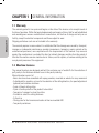
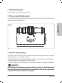
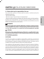
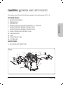
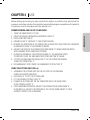
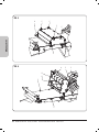
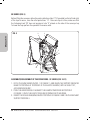
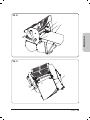
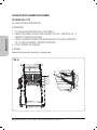
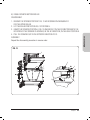
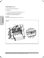
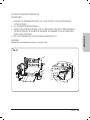
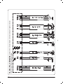
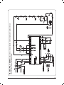
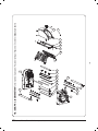
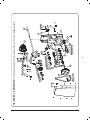
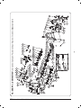
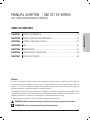
MANUAL SHEETER
SB/ ST/ SF SERIES
USE AND MAINTENANCE MANUAL
CHAPTER 1
GENERAL INFORMATION .................................................................................27
CHAPTER 2
INSTALLATION AND COMMISSIONING...........................................................32
CHAPTER 3
CONTROL AND SAFETY DEVICES.....................................................................34
CHAPTER 4
USE ................................................................................................................... 36
CHAPTER 5
MAINTENANCE ................................................................................................45
CHAPTER 6
DEMOLITION OF THE MACHINE.......................................................................46
CHAPTER 7
AFTER SALES SERVICE .....................................................................................46
Preface
This manual is directed towards those who install, operate and maintain the mixers so that they can take advantage
of the characteristics of the product in the best way. It is important that this manual is kept and remains with the
machine if it is moved or if ownership changes so that it can be consulted under all circumstances and therefore the
necessary information is available to operate it within safe conditions.
The manufacturer does not take upon themselves the obligation to give notice of possible successive modifications
of the product. Furthermore, under the terms of law, this document remains the property of the manufacturer, and
tampering, reproduction or transmission to a third party are prohibited without their consent.
In order to highlight certain parts of the text, the following symbols have been used:
ATTENTION: indicates situations of danger in which it is necessary to pay particular attention.
INFORMATION: refers to technical details of particular importance.
26
ENGLISH
TABLE OF CONTENTS
CHAPTER 1 GENERAL INFORMATION
1.1 Warranty
ENGLISH
The warranty period is two years and begins on the date of the invoice or tax receipt issued at
the time of purchase. Within that period replacements and repairs of items, that for well established
and unambiguous reasons are defective in manufacture, will be free of charge and only ex our
facility, except for electrical components and those subject to wear.
Shipping and labour costs are not included in the warranty.
The warranty expires in cases where it is established that the damage was caused by: transport,
improper or inadequate maintenance, operator inexperience, tampering, repairs carried out by
unauthorised personnel, non-compliance with the requirements of the manual. Any recourse
against the manufacturer is excluded for direct or indirect damages resulting from the period of
time that the machine remains inactive due to: failure, wait for repairs, or however relating to the
non-physical presence of the equipment.
1.2 Machine features
The manual sheeters are designed and built for exclusive use in foodstuffs for the reduction of
puff pastry to the thickness desired to use in the pastry industry.
Manual sheeters consist of:
· Basic structure stove-enamelled with epoxy powders, mounted on wheels for easy movement
· A dashboard for operation, a lever for the selection of the rolling direction, for speed adjustment
(optional) and machine shutdown
· A pair of dough rolling rollers
· A pair of conveyor belts of the product to be rolled
· Two pairs of scrapers to clean the rollers
· A handle to select the rolling thickness
· A flour tray
· Closing case for the transmission bodies in thermo-moulded ABS
· Two pastry containers
27
MANUAL SHEETER - SB/ST/SF SERIES Use and maintenance manual Edition 10-12
ENGLISH
1.3 Technical specifications
Model
Cylinder length
Cylinder diameter
Table length
Belt speed
Volt
Power
Weight
SB500-50
SB500-70
SB500-100
SB500-120
SB500P-50
SB500P-70
SB500P-100
SB500P-120
mm 500
mm 500
mm 500
mm 500
mm 500
mm 500
mm 500
mm 500
mm 60
mm 60
mm 60
mm 60
mm 60
mm 60
mm 60
mm 60
mm 500
mm 700
mm 1000
mm 1200
mm 500
mm 700
mm 1000
mm 1200
1
1
1
1
Variable
Variable
Variable
Variable
400/50/3
400/50/3
400/50/3
400/50/3
230/50/1
230/50/1
230/50/1
230/50/1
kw 0,55
kw 0,55
kw 0,55
kw 0,55
kw 0,55
kw 0,55
kw 0,55
kw 0,55
kg 150
kg 160
kg 170
kg 180
kg 150
kg 160
kg 170
kg 180
ST500-50
ST500-70
ST500-100
ST500-120
ST500P-50
ST500P-70
ST500P-100
ST500P-120
mm 500
mm 500
mm 500
mm 500
mm 500
mm 500
mm 500
mm 500
mm 60
mm 60
mm 60
mm 60
mm 60
mm 60
mm 60
mm 60
mm 500
mm 700
mm 1000
mm 1200
mm 500
mm 700
mm 1000
mm 1200
1
1
1
1
Variable
Variable
Variable
Variable
400/50/3
400/50/3
400/50/3
400/50/3
400/50/3
400/50/3
230/50/1
400/50/3
kw 0,55
kw 0,55
kw 0,55
kw 0,55
kw 0,55
kw 0,55
kw 0,55
kw 0,55
kg 180
kg 190
kg 200
kg 210
kg 180
kg 190
kg 200
kg 210
SF600-85
SF600-100
SF600-120
SF600-140
SF600P-85
SF600P-100
SF600P-120
SF600P-140
mm 600
mm 600
mm 600
mm 600
mm 600
mm 600
mm 600
mm 600
mm 80
mm 80
mm 80
mm 80
mm 80
mm 80
mm 80
mm 80
mm 850
mm 1000
mm 1200
mm 1400
mm 850
mm 1000
mm 1200
mm 1400
1
1
1
1
Variable
Variable
Variable
Variable
400/50/3
400/50/3
400/50/3
400/50/3
400/50/3
400/50/3
230/50/1
400/50/3
kw 0,75
kw 0,75
kw 0,75
kw 0,75
kw 0,75
kw 0,75
kw 0,75
kw 0,75
kg 250
kg 250
kg 260
kg 270
kg 250
kg 250
kg 260
kg 270
Model
Dimensions mm
A
B
C
D
E
F
G
SB500-50
SB500-70
SB500-100
SB500-120
500
500
500
500
500
700
1100
1300
1120
1520
2370
2770
2700
3100
380
380
380
380
700
700
700
700
920
920
920
920
ST500-50
ST500-70
ST500-100
ST500-120
500
500
500
500
500
700
1100
1300
1120
1520
2370
2770
2700
3100
580
580
580
580
1380
1380
1380
1380
920
920
920
920
SF600-85
SF600-100
SF600-120
SF600-140
600
600
600
600
966
1116
1316
1516
2070
2370
2770
3170
2585
2885
3285
3685
620
620
620
620
1163
1163
1163
1163
1055
1055
1055
1055
29
MANUAL SHEETER - SB/ST/SF SERIES Use and maintenance manual Edition 10-12
1.4 Electrical diagrams
For electrical diagrams refer to page 135-138.
1.5 Area occupied by the operator
Under normal operating conditions and for optimal use of the machine's capacities, the operator
requires the area outlined in FIG. 1.
ENGLISH
FIG. 1
mt 1,5
mt 2
1.6 General safety warnings
The machine, whilst conforming with safety requirements according to electrical, mechanical
and sanitary laws, can constitute a danger:
· If used for purposes and in conditions different from the ones foreseen by the manufacturer.
· Due to tampering of its protections and safety devices
· Failure to comply with the instructions for the installation, operation, usage and maintenance.
INFORMATION
All installation and maintenance operations must be carried out by qualified personnel
who are authorised by the manufacturer. The manufacturer declines any responsibility
arising from erroneous installation or tampering.
Chapter 1
30
1.7 Safety warnings
INFORMATION
Read these instructions carefully before using the machine.
ATTENTION
ENGLISH
In order to prevent dangerous conditions and/or possible injuries caused by electrical
currents, mechanical parts, fire or of a sanitary nature, the following safety warnings
must be observed:
A) Keep the place of work tidy. Untidiness can contribute to danger or accidents.
B) Evaluate environmental conditions. Do not operate the machine in a damp,
wet or insufficiently lit environment or in the vicinity of flammable liquids or gasses.
C) Keep children and unauthorised personnel away. Do not allow them to come near
to the machine or the place of work.
D) Operate the machine within its power rating for its permitted usage. It will operate
better and in a safer fashion if not overloaded.
E) Dress in a suitable manner. Do not wear loose fitting clothes or dangling accessories
that could get caught in the moving parts. Use anti-slip footwear. For sanitary as well
as safety reasons, cover long hair with a suitable net and wear gloves.
F) Protect the power cable. Do not tug the cable to disconnect the supply plug.
Do not expose the cable to elevated temperatures, sharp corners, water or solvents.
G) Avoid unstable positions. Find the most suitable position that always ensures equilibrium.
H) Always pay maximum attention. Observe your own work. Do not operate
the machine when distracted.
I) Disconnect the power supply at the end of operation, before cleaning
and maintenance operations, and before moving the machine.
L) Extension leads must not be used in the open air.
M) Check that the machine is not damaged. Before operating the machine, carefully check
the efficiency of the safety devices. Check that the moving parts are not blocked,
that there are no damaged components, that all of the parts are correctly fitted, and that
all conditions that could influence the regular operation of the machine are optimal.
N) The machine should be repaired by qualified personnel. The repair operations must be
carried out exclusively by qualified people using original replacement parts only.
Failure to observe these precautions can constitute an element of danger for the operator.
31
MANUAL SHEETER - SB/ST/SF SERIES Use and maintenance manual Edition 10-12
CHAPTER 2 INSTALLATION AND COMMISSIONING
The environmental conditions in the place where the machine is installed must have the
following characteristics:
· Must be without humidity
· Must have sources of water and heat at an adequate distant
· Must have suitable ventilation and lighting which reflect the sanitary and safety regulations
according to the current legislation. The floor must be flat and compact in order to favour
adequate cleaning. Obstacles of any nature which could effect normal ventilation must not be
placed in the immediate vicinity of the machine.
INFORMATION
The electrical supply must be fitted with a differential circuit breaker, with characteristics
which are adequate for the machine, in which the aperture distance between the contacts
is at least 3mm. In particular, it is essential that an efficient ground point is provided.
ATTENTION
Verify that the voltage supply and the frequency of the plant are compatible with the values
listed both in the technical details (1.3) and on the plate located on the back of the machine.
2.2 Installation procedure
SF/ST SERIES
The SF/ST series machines are supplied on wooden pallets on which they are secured with
metal brackets. In addition to the machine, the packaging contains the instructions for use and
the EC declaration of conformity according to the machinery directive. The machine must be
unloaded from the transport means by lifting it with the proper equipment.
Use a wheeled cart with proper capacity to transport the machine to the place of installation.
After removing the packaging and the plastic protection, unscrew the two metal brackets that
secure the machine to the pallet with a special wrench. With the aid of appropriate capacity
belts placed under the base of the machine and a suitable lifting means (manual or powered),
lift the machine, remove the underlying pallet, place it in the location foreseen, taking care
to leave a free space of approximately 50 cm around the machine in order to facilitate use,
Chapter 2
32
ENGLISH
2.1 Duties which are the responsibility of the user
cleaning and maintenance operations of the machine. For machines equipped with wheels,
make sure they have been braked by pressing down until lever A is locked (FIG. 2).
ENGLISH
FIG. 2
A
A
SB SERIES
SB series machines are supplied in cardboard boxes on wooden pallets. After removing the
packaging and the plastic protection, with the aid of appropriate capacity belts placed under
the base of the machine and a suitable lifting means (manual or powered), lift the machine,
remove the underlying pallet, place it in the foreseen location, taking care to leave a free
space of approximately 50 cm around the machine in order to facilitate use, cleaning and
maintenance operations of the machine.
Note: All items relating to the packaging must be disposed of according to the laws in force.
2.3 Electrical connection
The Y-type connection of the machine to the power supply is made using a mains cable that
comes with a plug in single-phase version only. For three-phase power supply machines, it is
essential to fit a normalised and polarised plug at the end of the cable (the distinction between
phase and neutral must be clear), and verify the correct direction of movement of the conveyors.
2.4 Positioning of the machine
The mains socket should be easily accessible and must not require any displacement. The distance
between the machine and the socket must be such as not to cause tension of the power supply
cable. Furthermore, the said cable should not be below the support feet of the machine.
33
MANUAL SHEETER - SB/ST/SF SERIES Use and maintenance manual Edition 10-12
CHAPTER 3 CONTROL AND SAFETY DEVICES
The machines are fitted with the following operation and safety devices: (FIG. 3-4):
OPERATION DEVICES
MAIN CIRCUIT BREAKER
START BUTTON
STOP BUTTON
CONVEYOR SPEED ADJUSTMENT (OPTIONAL) "P" VERSIONS
CONVEYOR REVERSE MANUAL CONTROL LEVER
CONVEYOR REVERSE MANUAL CONTROL PEDAL
DOUGH THICKNESS ADJUSTMENT LEVER
ENGLISH
ABCDEFG-
G0 - MECHANICS UNIT
G3 - BASE
G4 - CONVEYOR BELT ARM
G5 - CUTTING UNIT
SAFETY DEVICES
H - ROLLING ROLLERS PROTECTION
FIG. 3
G4
G5
D C B G H
H G0
E
I
L
G4
G3
A
F
Chapter 3
34
CHAPTER 4 USE
Before starting each work cycle make sure that the machine is perfectly clean, particularly the
conveyors and rolling cylinders that should be treated with detergents compatible with foodstuffs.
If necessary, clean in accordance with the methods in 5.1.
1.
2.
3.
4.
5.
6.
7.
8.
9.
TURN THE MAIN SWITCH "A" ON 1
OPEN THE DOUGH THICKNESS ADJUSTMENT LEVER "G"
PRESS START BUTTON "B"
OPERATE LEVER "E" OR PEDAL "F" AND START ROLLING
REVERSE THE DIRECTION OF THE CONVEYORS AT EACH STEP, SELECTING THE THICKNESS
BY MEANS OF LEVER "G" ACCORDING TO NEEDS
ADJUST THE SPEED OF THE CONVEYORS USING KNOB "D" IN MACHINES EQUIPPED
WITH VARIABLE SPEED CONTROL (OPTIONAL)
IN CASE OF OPENING OF THE PROTECTION GRID "H" THE MACHINE STOPS.
TO RESTART, CLOSE THE GRID AND PRESS START BUTTON "B" AGAIN
TO STOP THE MACHINE POSITION LEVER "E" AT THE CENTRE OR REMOVE
YOUR FOOT FROM PEDAL "F".
FOR EMERGENCY STOP, PRESS THE EMERGENCY STOP BUTTON "D"
USING THE CUTTING UNIT (FIG.5-6)
1 . ASSEMBLE THE CUTTING UNIT ON THE LEFT SIDE OF THE MACHINE
USING THE SCREWS PROVIDED.
2 . USE LEVER "A" TO LIFT THE CUTTING UNIT
3 . FIT THE DESIRED CUTTING TOOLS "B"
4 . LOWER THE CUTTING UNIT ON THE CONVEYOR UNTIL THE SAME LOCKS
IN THE SPECIAL HOOKS "C"
5 . START MACHINE OPERATION, ADJUST THE DESIRED SPEED USING KNOB "D"
IN FIGURES 3/4, ADJUST THE PRESSURE OF THE TOOLS USING KNOBS "E" UNTIL
A PERFECT PASTRY CUT IS OBTAINED
Chapter 4
36
ENGLISH
COMMISSIONING AND USE OF THE MACHINE
FIG. 5
E
A
E
E
ENGLISH
E
C
FIG. 6
A
B
B
C
C
37
MANUAL SHEETER - SB/ST/SF SERIES Use and maintenance manual Edition 10-12
E
E
SB SERIES (FIG. 9)
Before lifting the conveyors allow the pasta collection slides "S" (if provided) on the left and right
of the tops to recess, raise the roller protections "H". Raise one top at a time; make sure that
the fastening knob "M" does not engage in hole "K" placed on the side of the conveyor top.
To lower the tops perform the operation in reverse order.
FIG. 9
H
ENGLISH
H
K
M
K
M
ASSEMBLY/DISASSEMBLY OF THE CONVEYORS - SF SERIES (FIG. 10-11)
1 . FETCH THE ARM SHOWN IN POS. 1 OF FIGURE 11 AND DRAW THE SUPPORT INDICATED
NEAR TO POSITION 5 AT POSITION 2 OF THE ELASTIC ELEMENT, WITH A SLIGHT TILT,
AS SHOWN IN FIGURE 1
2 . PUSH THE ARM FORCEFULLY AGAINST THE ELEMENT INDICATED IN POSITION 2
OF FIGURE 1, UNTIL THE ELASTIC ITEM HAS RETURNED IN ITS HOUSING.
3 . INSERT THE ROLLER DRAGGING DEVICE POSITION 3 OF FIGURE 2 AND 3 IN THE RELEVANT
SUPPORT POSITION 4.
39
MANUAL SHEETER - SB/ST/SF SERIES Use and maintenance manual Edition 10-12
FIG. 10
2
5
1
ENGLISH
3
FIG. 11
1
4
3
Chapter 4
40
DOUGH SCRAPER ASSEMBLY/DISASSEMBLY
SF SERIES (FIG. 12-13)
A) DOUGH SCRAPER UPPER ROLLER
ENGLISH
DISASSEMBLY
1 . LIFT THE ROLLER PROTECTION FIG. 12 POSITION H.
2 . GRASP THE SPRING POSITION T AND PULLING IT IN THE F1 DIRECTION, FIG. 12
UNHOOK IT FROM PEG POSITION P.
3 . GRASP THE DOUGH SCRAPER POSITION R AND MOVE IT IN THE F2 DIRECTION
FIG. 12, UNTIL RELEASING IT FROM PEG POSITION Q.
4 . LASTLY, REMOVE THE SCRAPER.
ASSEMBLY
Repeat the disassembly procedure in reverse order.
FIG. 12
P
F1
P
T
A
H
P
T
R
U
F2
R
Q
T
41
MANUAL SHEETER - SB/ST/SF SERIES Use and maintenance manual Edition 10-12
B) DOUGH SCRAPER BOTTOM ROLLER
DISASSEMBLY
1. REMOVE THE SPRINGS POSITION T FIG. 13 AS DESCRIBED IN PARAGRAPH 2
FOR THE UPPER ROLLER.
2. LIFT THE ROLLER PROTECTION FIG. 13 POSITION H.
3 . GRASP THE SCRAPER POSITION U, FIG. 13 AND MOVE IT IN THE F3 DIRECTION UNTIL THE
ROTATION OF THE SCRAPER IS ACHIEVED, IN THE B1 DIRECTION, IN THE HOLE POSITION K.
4 . PULL THE SCRAPER OUT IN THE OPPOSITE DIRECTION TO F3.
ENGLISH
ASSEMBLY
Repeat the disassembly procedure in reverse order.
FIG. 13
H
U
T
T
A
T
P
T
B1
K
F3
P
T
Chapter 4
42
ST/SB SERIES (FIG. 14-15)
A) DOUGH SCRAPER UPPER ROLLER
DISASSEMBLY
ENGLISH
1. LIFT THE ROLLER PROTECTION POSITION H FIG. 14.
2 . UNSCREW THE FLYWHEELS POSITION M.
3 . REMOVE THE SCRAPER POSITION R.
ASSEMBLY
Repeat the disassembly procedure in reverse order.
FIG. 14
M M
H
M
R
U
A
M
43
MANUAL SHEETER - SB/ST/SF SERIES Use and maintenance manual Edition 10-12
R
B) DOUGH SCRAPER BOTTOM ROLLER
DISASSEMBLY
ENGLISH
1 . REMOVE THE SPRINGS POSITION T, FIG. 15 AS IN STEP 2 OF THE UPPER ROLLER
OF THE SF SERIES.
2 . LIFT THE PROTECTION POSITION H.
3 . GRASP THE SCRAPER POSITION U, FIG. 15 AND MOVE IT IN THE F1 DIRECTION UNTIL
THE ROTATION OF THE SCRAPER IS ACHIEVED, ACCORDING TO THE B1 DIRECTION,
IN THE HOLE POSITION K.
4 . PULL THE SCRAPER OUT IN THE OPPOSITE DIRECTION TO F1
ASSEMBLY
Repeat the disassembly procedure in reverse order.
FIG. 15
H
K
B1
T
A
U
P
P
T
T
P
T
F1
T T
Chapter 4
44
CHAPTER 5 MAINTENANCE
ATTENTION
ENGLISH
Disconnect the plug from the electricity supply before carrying out any maintenance or
cleaning interventions. In case of the malfunctioning or breakdown of the machine, contact
only the assistance centres authorised by the manufacturer.
5.1 Cleaning
Cleaning should be done at the end of each usage in compliance with hygiene requirements and
to protect the functionality of the machine.
With the aid of a suction machine, remove all residues of flour and dough. Remove the dough
scraper before cleaning the cylinders (Fig. 12/13 for SF) and (Fig. 14/15 for SB/ST).
Remove residues of dough and flour using a soft sponge and warm water, dry with absorbent
paper for food, then first go over the areas mentioned, and then the whole machine with a soft,
clean cloth moistened with specific disinfectant for food machines.
ATTENTION
It is recommended not to use non-food abrasive or corrosive chemicals in any case.
Absolutely avoid using water jets, various tools, rough or abrasive means such as steel
scouring pads, sponges, etc. that may damage the surfaces and above all compromise the
safety from a sanitary standpoint. To maintain both performance efficiency and the safety
of the machine, it is essential to carry out periodic maintenance of the following items
(at least once every 6 months).
45
MANUAL SHEETER - SB/ST/SF SERIES Use and maintenance manual Edition 10-12
CHAPTER 6 DEMOLITION OF THE MACHINE
In case of dismantling and demolition of the machine, the parts that compose it do not present
a hazard degree requiring the adoption of specific precautions. To facilitate recycling of materials,
all parts that make up the electrical system must be separated from the machine.
ENGLISH
CHAPTER 7 AFTER SALES SERVICE
7.1 Spare parts
For the request of spare parts please refer to FIG. 20-30.
ATTENTION
We recommend using only original spare parts.
The European Union states:
Contact your dealer only.
Chapter 6/7
46
135
Edizione / Edition / Édition / Edición / Ausgabe / Издание: 10-12
FIG. / ABB. / РИС. 16 - SB500-ST500 Schema elettrico / Electrical diagram / Schemas electriques / Diagramas eléctricos
Elektroschaltpläne / Электрические схемы
Edizione / Edition / Édition / Edición / Ausgabe / Издание: 10-12
136
FIG. / ABB. / РИС. 17 - SB500P Schema elettrico / Electrical diagram / Schemas electriques / Diagramas eléctricos
Elektroschaltpläne / Электрические схемы
139
FIG. / ABB. / РИС. 20 - SB500-ST500 Parti di ricambio / Spare parts / Pieces de rechange / Repuestos / Ersatzteile / Запасные части
114
G1
14
Edizione / Edition / Édition / Edición / Ausgabe / Издание: 10-12
143
52
210
143
66
209
93
59
40
41
7
214
1
2
214
33
32
34
G2
14
Edizione / Edition / Édition / Edición / Ausgabe / Издание: 10-12
140
51
143
145 144
132 131
144
130
85
48
37
119
111
28
136
123
144 129
120
132
131
135 137
29
29
15
61
10
18
21
118 54
39 141
3
137
158
127 128
124 125 158 132 144
175
83
21 146
100 109 110
158
124 125
36 103 175 108 107 112 109
175
106
136
31
43
13
35
84
12
55
126 125 124
93
FIG. / ABB. / РИС. 21 - SB500-ST500 Parti di ricambio / Spare parts / Pieces de rechange / Repuestos / Ersatzteile / Запасные части
141
Edizione / Edition / Édition / Edición / Ausgabe / Издание: 10-12
154
115
55
125
124
163
126
84
35
13
170 169
31
146 162
150
125
158
11
175
165
124
20
27
175
140
158
3
124
98
95 142
133
125
95 133
83
13
118 130 131 134
140
164 148 39
114 127 54
56
174
57
140
201
177
SB500P
9
181
24
SB500
ST500
142
5
122
168
25
5
25
27
125 124 156
6
26
149 175 127
158 175 125 140 124
205
158 4
82
21
8
23
131
98
143
183 155
125 124
50
63
151
187
200
180
47
62
SB500P
ST500P
179
219
166
178
53
153
157
152
46
166
FIG. / ABB. / РИС. 22 - SB500-ST500 Parti di ricambio / Spare parts / Pieces de rechange / Repuestos / Ersatzteile / Запасные части
167
68
Edizione / Edition / Édition / Edición / Ausgabe / Издание: 10-12
142
79;80
81
199
42
22
ST500-100
ST500-120
197
198
16
185
17
81
196
197
188
197
197
81
42
81 216
42
30
SB500-100
SB500-120
59
217
202
203
186
193
197
194
195 204 204 204
199 192 191 49
19
131
208
207
17
22
190
81
16
189
81
42
204
218 195
74;76
30
197
194
191
193
199 192 49 207 208
19
200
SB500-50; SB500-70
ST500-50; ST500-70
ST500-100
ST500-120
FIG. / ABB. / РИС. 23 - SB500-ST500 Parti di ricambio / Spare parts / Pieces de rechange / Repuestos / Ersatzteile / Запасные части
143
Edizione / Edition / Édition / Edición / Ausgabe / Издание: 10-12
105 115
103
86
87
101
175 102
121
175
44
113
99
121
175
45
117
96
131
213
175
102
98
175
45
94
97
116
64
102
91
101
100
175
103
104
65
90
92
89
88
ST500P/SF600P
FIG. / ABB. / РИС. 24 - SB500-ST500 Parti di ricambio / Spare parts / Pieces de rechange / Repuestos / Ersatzteile / Запасные части
86
87