1
[Disposal Precautions]
[Installation Precautions]
AJ65BT-68TD
Thermocouple
Temperature Input Module
Mitsubishi General-Purpose Programmable Controller
User’s Manual
(Hardware)
Thank you for purchasing the Mitsubishi general-purpose
programmable controller MELSEC-A series.
Prior to use, please read this manual thoroughly and
familiarize yourself with the product.
Type
AJ65BT68TD-U-HW-E
Type
13JL49
Code
IB(NA)-66830-F(0810)MEE
Item
CAUTION
CAUTION
• Use the programmable controller in an environment that meets the general
specifications in this manual.
Failure to do so may result in electric shock, fire, malfunction, or damage to
or deterioration of the product.
• For protection of the switches, do not remove the cushioning material before
installation.
• Securely fix the module with a DIN rail or mounting screws. Tighten the
screws within the specified torque range.
Undertightening can cause drop of the screw, short circuit or malfunction.
Overtightening can damage the screw and/or module, resulting in drop,
short circuit, or malfunction.
• Do not directly touch any conductive part of the module.
Doing so can cause malfunction or failure of the module.
• When disposing of this product, treat it as industrial waste
The following are manuals related to this product.
Request for the manuals as needed according to the chart below.
Manual Name
Manual No.
(Model Code)
AJ65BT-68TD Thermocouple Temperature Input Module User's
Manual
Insulation method
Thermocouple input to CC-Link transmission
: Transfer insulation
Between channels
: Transfer insulation
Related Manuals
AJ61BT11/A1SJ61BT11 CC-Link System Master · Local Module
User's Manual
AJ61QBT11/A1SJ61QBT11 CC-Link System Master · Local Module
User's Manual
Control & Communication Link System Master/Local Module type
QJ61BT11N User's Manual
IB-66721
(13J872)
IB-66722
(13J873)
SH-080394
(13JR64)
Insulation resistor
Connected terminal block
Applicable wire size
Applicable solderless terminal
Module mounting screw
1. Overview
This user's manual explains the specifications, handling, programming
methods, etc. of the AJ65BT-68TD Thermocouple Input Module
(hereinafter referred to as AJ65BT-68TD) used as a remote device station
for the CC-Link system.
The AJ65BT-68TD is a module that converts the thermocouple input
values from outside the programmable controller to the temperature values
or scaling values of 16-bit signed BIN data.
Depends on noise simulator of noise voltage at 500Vp-p,
noise width at 1ms and noise frequency at 25 to 60 Hz
Dielectric withstand voltage
SH-3304
(13JL52)
Manual No.
(Model Code)
Specification
CC-Link dedicated cable
Between batch power supply system and ground
Between batch power supply system and batch
communication system
Between batch communication system and batch
thermocouple input
Between batch thermocouple input and ground
500 V AC, 1 minute
Detailed Manual
Manual Name
• Shut off the external power supply for the system in all phases before wiring.
Failure to do so may result in damage to the product.
• After installation or wiring, attach the included terminal cover to the module
before turning it on for operation.
Undertightening can cause short circuit or malfunction.
• Ground the FG terminals to the protective ground conductor dedicated to the
programmable controller.
Failure to do so may result in malfunction.
• Use applicable solderless terminals and tighten them within the specified
torque range. If any spade solderless terminal is used, it may be disconnected
when the terminal screw comes loose, resulting in failure.
• Check the rated voltage and terminal layout before wiring to the module, and
connect the cables correctly.
Connecting a power supply with a different voltage rating or incorrect wiring
may cause a fire or failure.
• Tighten the terminal screw within the specified torque range.
Undertightening can cause short circuit or malfunction.
Overtightening can damage the screw and/or module, resulting in drop, short
circuit, or malfunction.
• Prevent foreign matter such as dust or wire chips from entering the module.
Such foreign matter can cause a fire, failure, or malfunction.
Noise durability
About Manuals
[Wiring Precautions]
CAUTION
Connection cable
Applicable DIN rail
External power supply
Internal consumption current
Allowable momentary power
failure period
Weight
Between batch power supply system and ground
Between batch power supply system and batch
communication system
Between batch communication system and batch
thermocouple input
Between batch thermocouple input and ground
500 V DC, more than 10 M Ω by the insulation resistance
taster
27-point terminal blocks (M3.5 × 7 screws)
0.75 to 2.00 mm2
RAV1.25-3.5, RAV2-3.5 (Conforms to JIS C 2805)
Screws M4 × 0.7 mm × 16 mm or larger (tightening torque range
78 to 118 N • cm {8 to 12 kg • cm})
May be attached using DIN rails
TH 35-7.5 Fe, TH 35-7.5 Al, TH 35-15 Fe
(conform to JIS C 2812)
24 V DC (18 to 30 V DC)
0.081 A (at 24VDC)
1 ms
0.40 (0.88) kg (lb.)
C 1996 MITSUBISHI ELECTRIC CORPORATION
SAFETY PRECAUTIONS
(Read these precautions before using this product.)
Before using this product, please read this manual and the relevant manuals carefully
and pay full attention to safety to handle the product correctly.
These precautions apply only to Mitsubishi equipment. Refer to the CPU module user’s
manual for a description of the programmable controller system safety precautions.
In this manual, the safety precautions are classified into two levels: "DANGER" and
"CAUTION".
DANGER
Indicates that incorrect handling may cause hazardous
conditions, resulting in death or severe injury.
CAUTION
Indicates that incorrect handling may cause hazardous
conditions, resulting in minor or moderate injury or property
damage.
Under some circumstances, failure to observe the precautions given under "
CAUTION" may lead to serious consequences.
Observe the precautions of both levels because they are important for personal and
system safety.
Make sure that the end users read this manual and then keep the manual in a safe place
for future reference.
[Design Precautions]
DANGER
• In the case of a communication failure in the network, data in the master
module are held.
Check the communication status information (SB, SW) and configure an
interlock circuit in the sequence program to ensure that the entire system
will operate safely.
CAUTION
• Do not install the control lines or communication cables together with the
main circuit lines or power cables.
Keep a distance of 100mm (3.94 inches) or more between them.
Failure to do so may result in malfunction due to noise.
[Wiring Precautions]
2. EMC and Low-Voltage Commands
CAUTION
• Place the cables in a duct or clamp them.
If not, dangling cable may swing or inadvertently be pulled, resulting in damage
to the module or cables or malfunction due to poor contact.
• Do not install the control lines or communication cables together with the main
circuit lines or power cables. Failure to do so may result in malfunction due to
noise.
• When disconnecting the cable from the module, do not pull the cable by the
cable part. Loosen the screws of connector before disconnecting the cable.
Failure to do so may result in damage to the module or cable or malfunction
due to poor contact.
(1) For programmable controller system
To configure a system meeting the requirements of the EMC and Low
Voltage Directives when incorporating the Mitsubishi programmable
controller (EMC and Low Voltage Directives compliant) into other machinery
or equipment, refer to the "EMC AND LOW VOLTAGE DIRECTIVES"
chapter of the User's Manual for the CPU module used.
The CE mark, indicating compliance with the EMC and Low Voltage
Directives, is printed on the rating plate of the programmable controller.
(2) For the product
For the compliance of this product with the EMC and Low Voltage Directives,
refer to the "CC-Link module" section in the "EMC AND LOW VOLTAGE
DIRECTIVES" chapter of the User's Manual for the CPU module used.
[Starting and Maintenance Precautions]
CAUTION
• Do not touch any terminal while power is on.
Doing so may cause malfunction.
• Shut off the external power supply for the system in all phases before cleaning the
module or retightening the terminal screws.
Failure to do so may cause the module to fail or malfunction.
Undertightening the terminal screws can cause short circuit or malfunction.
Overtightening can damage the screw and/or module, resulting in drop, short
circuit, or malfunction.
• Do not disassemble or modify the module.
Doing so may cause failure, malfunction, injury or a fire.
• Do not drop or apply any strong shock to the module.
Doing so may damage the module.
• Shut off the external power supply for the system in all phases before mounting or
removing the module to or from the panel.
Failure to do so may cause the module to fail or malfunction.
• Mounting/removing the terminal block is limited to 50 times after using a product.
(IEC61131-2-compliant)
• Before handling the module, touch a grounded metal object to discharge the
static electricity from the human body.
Failure to do so may cause the module to fail or malfunction.
3. Specification
3.1
Performance Specification
The performance specification of the AJ65BT-68TD are shown below.
And, refer to master module user's manual which is used about the general
specification.
Item
Temperature sensor input
Output
Specification
–200 to 1700°C
Detected
temperature
16-bit signed binary (–2000 to 17000 : value to one decimal
place multiplied by 10)
Scaling value
16-bit signed binary (0 to 2000)
Applicable thermocouples and
temperature measurement
range accuracy *1
Cold junction compensation
accuracy
Overall accuracy
Maximum resolution
Conversion speed
(sampling time)
Absolute maximum input
Number of analog input points
CC-Link station type
Number of occupied stations
Refer to Table 3.1
± 1.0°C
By the calculation of *2
B, R, S : 0.3 °C
K, E, J, T : 0.1 °C
45 ms/ch
±5V
8-channel + Pt 100 connection channel
Remote device station
4 Stations : RX/RY 128 points each
RWw/RWr 16 points each
*1 : The thermocouple type can be set using the remote register
RY (n + 1) 0 to RY (n + 5) 6 for each channel.
*2 : Overall accuracy computation method is as follows:
(Overall accuracy) = (Conversion accuracy) + (Temperature
characteristics) × (Ambient operating temperature change) + (Cold
junction compensation accuracy)
The ambient operating temperature change refers to the value that falls
outside the range of 25 ±5 °C.
Example) The overall accuracy when using thermocouple K, measured
temperature 150 °C, ambient operating temperature 35 °C will be:
(± 0.5 °C) + (± 0.06 °C) × (5 °C) + (± 1 °C) = ± 1.8 °C
± 2.5 °C
± 2.0 °C
200 to 1600
± 0.3 °C
0 to 200
(4) Tighten the module mounting screws within the following torque range.
± 2.0 °C
Screw area
200 to 1600
± 0.3 °C
– 200 to 0
±0.06 °C or ±0.3 % of the measured
temperature, whichever is greater
0 to 1200
±0.06 °C or ±0.02 % of the
measured temperature, whichever
is greater
– 200 to 0
±0.06 °C or ±0.3 % of the measured
temperature, whichever is greater
K
E
0 to 750
T
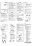
4. Name of Each Part
Terminal block terminal screws (M3.5 screw)
59 to 88 N · cm
98 to 137 N · cm
9.5
B RATE STATION NO.
X10
X1
MELSEC AJ65BT-68TD
SW
0
1-8
9
(a) Applicable DIN rail types (conform to JIS C 2812)
MODE
NORMAL
TEST CH.
TEST
PW
RUN
L RUN
SD
RD
L ERR.
01
2
3
4
01
901
2 8
2
3 7
3
654
654
MODE OFFSET UP
901
8
2
7
3
654
SET
GAIN DOWN
RESET
142.9(5.63)
TH 35-7.5 Fe
TH 35-7.5 Al
TH 35-15 Fe
151.9 (5.98)
(b) Space between DIN rail mounting screws
Unit: mm (in.)
When installing a DIN rail, tighten the screws with a space of less
than 200 mm (7.9 in.).
1)
RESET
SET
6)
Terminate
resistor
GAIN DOWN
DA
DB
DG
5)
SLD
FG
AJ65BT-68TD
(Blue)
(White)
(Yellow)
I/O module, etc.
DA
DA
DB
DB
DG
CC-Link dedicated
cable
SLD
FG
Pt 100
Terminate
resistor
DG
CC-Link dedicated
cable
SLD
FG
CH1
+
8)
Number
7) 3) 4)
Name
1)
Station setting switch
2)
Transmission baud rate setting switch
3)
Mode switch
4)
Offset/gain setting switch
5)
UP/DOWN switch
6)
Reset switch
9)
–
Point
For the modules at both ends of the data link, make sure to connect the "terminal
resistor" that is attached to a master module (connect between DA and DB).
CH8
+
–
PW
*1
RUN
L RUN
SD
RD
*2
L ERR.
8)
Terminal block
9)
Temperature-measuring resistor Pt 100
Mitsubishi Electric shall not be liable for any loss caused by reasons for which Mitsubishi is not held
accountable, lost business opportunities or unrealized gain on the customer's side resulting from failure of
the product, or any other damage, secondary disaster, accident, damage to equipment other than the
product or disruption of other business operations arising out of special circumstances which may or may
not have been predicted at Mitsubishi.
This product is manufactured as a general-purpose product intended for general industrial use only. It is
not designed nor manufactured for use in an equipment or system affecting human lives.
If you are considering to use this product in equipment or systems for nuclear power generation, power
generation, aerospace, medical or passenger transport applications, consult our sales representatives.
This product is manufactured under our strict quality control system. However, if the product is used in the
intended facility in such a way that a failure of the product may lead to serious accident or loss,
incorporate backup or fail-safe functions into the system design.
Transfer
Master module side
Transfer
MODE OFFSET UP
901
8
2
7
3
654
RTD
01
901
2 8
2
3 7
3
654
654
Warranty
For safe use of the product
Input amplifier
01
2
3
4
Wiring Example with Each CC-Link Modules
Input amplifier
PW
RUN
L RUN
SD
RD
L ERR.
Example of Connecting Module
The following shows the wiring example between AJ65BT-68TD and
thermocouple.
The following shows the connection between the AJ65BT-68TD and
master module using twisted cables.
B RATE STATION NO.
X10
X1
MELSEC AJ65BT-68TD
MODE
NORMAL
TEST CH.
TEST
6.1
6.3
Input amplifier
2)
LED display
MITSUBISHI
(5) When using a DIN rail adapter, install the DIN rail considering the
precautions described below.
6. Wiring
The name of each part in the AJ65BT-68TD is described.
7)
2- ø4.5 installing hole
±0.06 °C or ±0.02 % of the
measured temperature, whichever
is greater
0 to 350
SW
0
1-8
9
NP
78 to 118 N · cm
Terminal block mounting screws (M3.5 screw)
±0.06 °C or ±0.3 % of the measured
temperature, whichever is greater
– 200 to 0
Tightening torque range
Module mounting screws (M4 screw)
±0.5 °C or ±0.25 % of ±0.06 °C or ±0.02 % of the
the measured
measured temperature, whichever
temperature, whichever is greater
is greater
±0.06 °C or ±0.02 % of the
measured temperature, whichever
is greater
0 to 800
MITSUBISHI
(2) Always place a thermocouple at least 10 cm (3.94 in.) apart from the
main circuit line and AC control circuit line. Place a thermocouple
sufficiently apart from circuits with high frequency, such as high-voltage
lines and inverter load main circuits. If they are placed close to each
other, the thermocouple is influenced more easily by the noise, surge,
or conductivity.
± 0.4 °C
S
J
(1) Use separate cables for the AC and the external input signals of the
AJ65BT-68TD, in order not to be affected by the AC side surge or
conductivity.
(3) Be careful not to let foreign matter such as filings or wire chips get
inside the module while wiring. Remove all foreign matters if any get
inside.
± 0.4 °C
R
The following describes the external wiring precautions.
(2) Do not take the printed circuit board of the module out of the case. It
may result in a failure.
± 0.4 °C
0 to 200
Handling Precautions
(1) Because it is made of resin, do not drop or given a strong shock to the
module case and the terminal block.
(0.37)
5.1
63 (2.48)
600 to 1700
Temperature characteristic
(Per 1 °C of ambient operating
temperature change)
7. External Dimensions Diagram
56 (2.2)
Conversion accuracy
(When ambient
operating 25 ± 5 °C)
Precautions when Wiring
To obtain maximum performance from the functions of AJ65BT-68TD and
improve the system reliability, a wiring with high durability against noise is
required.
Filter
B
Temperature
measurement
range [°C ]
6.2
Filter
Applicable
thermocouple
type
5. Handling
65 (2.56)
Table 3.1 Applicable thermocouples and temperature measurement range
accuracy
*1 Be sure to use the shielded compensating conductor for the cable.
*2 Be sure to ground.
Country/Region Sales office/Tel
Country/Region Sales office/Tel
U.S.A
Mitsubishi Electric Automation Inc.
Hong Kong
Mitsubishi Electric Automation
(Hong Kong) Ltd.
500 Corporate Woods Parkway Vernon
10th Floor, Manulife Tower, 169 Electric
Hills, IL 60061, U.S.A.
Road, North Point, Hong Kong
Tel : +1-847-478-2100
Tel : +852-2887-8870
Brazil
MELCO-TEC Rep. Com.e Assessoria
China
Mitsubishi Electric Automation
Tecnica Ltda.
(Shanghai) Ltd.
Rua Correia Dias, 184,
4/F Zhi Fu Plazz, No.80 Xin Chang Road,
Edificio Paraiso Trade Center-8 andar
Shanghai 200003, China
Paraiso, Sao Paulo, SP Brazil
Tel : +86-21-6120-0808
Tel : +55-11-5908-8331
Taiwan
Setsuyo Enterprise Co., Ltd.
Germany
Mitsubishi Electric Europe B.V. German
6F No.105 Wu-Kung 3rd.Rd, Wu-Ku
Branch
Hsiang, Taipei Hsine, Taiwan
Gothaer Strasse 8 D-40880 Ratingen,
Tel : +886-2-2299-2499
GERMANY
Korea
Mitsubishi Electric Automation Korea
Co., Ltd.
Tel : +49-2102-486-0
1480-6, Gayang-dong, Gangseo-ku
U.K
Mitsubishi Electric Europe B.V. UK
Seoul 157-200, Korea
Branch
Tel : +82-2-3660-9552
Travellers Lane, Hatfield, Hertfordshire.,
Singapore
Mitsubishi Electric Asia Pte, Ltd.
AL10 8XB, U.K.
307 Alexandra Road #05-01/02,
Tel : +44-1707-276100
Mitsubishi Electric Building,
Italy
Mitsubishi Electric Europe B.V. Italian
Singapore 159943
Branch
Tel : +65-6470-2460
Centro Dir. Colleoni, Pal. Perseo-Ingr.2
Thailand
Mitsubishi Electric Automation (Thailand)
Via Paracelso 12, I-20041 Agrate Brianza.,
Co., Ltd.
Milano, Italy
Bang-Chan Industrial Estate No.111
Tel : +39-039-60531
Moo 4, Serithai Rd, T.Kannayao,
Spain
Mitsubishi Electric Europe B.V. Spanish
A.Kannayao, Bangkok 10230 Thailand
Tel : +66-2-517-1326
Branch
Indonesia
P.T. Autoteknindo Sumber Makmur
Carretera de Rubi 76-80,
Muara Karang Selatan, Block A/Utara
E-08190 Sant Cugat del Valles,
No.1 Kav. No.11 Kawasan Industri
Barcelona, Spain
Pergudangan
Jakarta - Utara 14440,
Tel : +34-93-565-3131
P.O.Box 5045 Jakarta, 11050 Indonesia
France
Mitsubishi Electric Europe B.V. French
Tel : +62-21-6630833
Branch
India
Messung Systems Pvt, Ltd.
25, Boulevard des Bouvets, F-92741
Electronic Sadan NO:III Unit No15,
Nanterre Cedex, France
M.I.D.C Bhosari, Pune-411026, India
TEL: +33-1-5568-5568
Tel : +91-20-2712-3130
South Africa
Circuit Breaker Industries Ltd.
Australia
Mitsubishi Electric Australia Pty. Ltd.
Private Bag 2016, ZA-1600 Isando,
348 Victoria Road, Rydalmere,
South Africa
N.S.W 2116, Australia
Tel : +27-11-928-2000
Tel : +61-2-9684-7777
HEAD OFFICE : TOKYO BUILDING, 2-7-3 MARUNOUCHI, CHIYODA-KU, TOKYO 100-8310, JAPAN
NAGOYA WORKS : 1-14, YADA-MINAMI 5-CHOME, HIGASHI-KU, NAGOYA, JAPAN
When exported from Japan, this manual does not require application to the Ministry
of Economy, Trade and Industry for service transaction permission.
Specifications subject to change without notice.
Printed in Japan on recycled paper.