1
[Design Precautions]
CAUTION
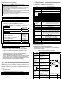
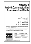
RS-232C Interface Module
type AJ65BT-R2
Do not bind the control wire or communication cable with the main circuit or
power wire, or place the control wire near these.
Separate by at least 100mm or more.
Failure to observe this could lead to malfunctions caused by noise.
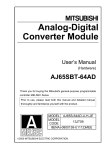
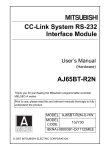
Always connect the master module and CC-Link dedicated cable at the data
link terminal block.
If the data link terminal block and general-purpose input/output terminal
block are incorrectly inserted, module trouble could occur.
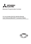
User’s Manual
(Hardware)
AJ65BT-R2
Thank you for purchasing the Mitsubishi program logic controller
MELSEC-A series.
Prior to use, please read this and relevant manuals thorougly
to fully understand the product.
MODEL AJ65BT-R2-U-HW-E
MODEL
13JL23
CODE
IB(NA)-66780-C(0604)MEE
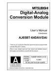
Data link terminal
block
General-purpose input/
output terminal block
[Mounting Precautions]
CAUTION
Use the module in an environment that meets the general specifications
given in the RS-232C Interface Module Type AJ65BT-R2 User’s Manual.
Using it outside the general specifications could lead to electric shocks,
fires, malfunctioning, product damage or deterioration.
Always connect the crimp, press-fit or solder the connector wire connections
with the maker-designated tools, and securely connect the connector to the
module.
An incomplete connection could lead to short-circuits or malfunctioning.
Do not directly touch the conductive section of the module.
Failure to observe this could lead to module malfunctioning or trouble.
Securely fix the module with the DIN rail or installation screw. Tighten the
installation screw within the designated torque range.
A loose screw could lead to dropping, short-circuiting or malfunctioning.
If the screw is too tight, dropping or short-circuiting could occur due to screw
damage.
Securely mount the connector of each connection cable to the mounting
section.
An incomplete connection could lead to malfunctioning caused by an
incorrect contact.
[Wiring Precautions]
1997 MITSUBISHI ELECTRIC CORPORATION
SAFETY PRECAUTIONS
(Always read these instructions before using this equipment.)
Before using this product, please read this manual and the relevant
manuals introduced in this manual carefully and pay full attention to
safety to handle the product correctly.
The instructions given in this manual are concerned with this product.
For the safety instructions of the programmable controller system,
please read the CPU module user's manual.
In this manual, the safety instructions are ranked as "DANGER" and
"CAUTION".
DANGER
Indicates that incorrect handling may cause hazardous
conditions, resulting in death or severe injury.
CAUTION
Indicates that incorrect handling may cause hazardous
conditions, resulting in medium or slight personal injury
or physical damage.
CAUTION level may lead to a serious consequence
Note that the
according to the circumstances.
Always follow the instructions of both levels because they are important
to personal safety.
Please save this manual to make it accessible when required and
always forward it to the end user.
[Design Precautions]
DANGER
If a communication error occurs in the data link, the following will occur
in the station having the communication error.
Use the communication status information, and configure an interlock
circuit in the sequence program so that the system will operate safely.
Incorrect outputs and incorrect operations can lead to accidents.
(1) All points of the general-purpose input from this module will turn
OFF.
(2) All points of the general-purpose output from this module will turn
OFF.
The input/output may turn ON or OFF depending on the module trouble.
Provide a circuit that externally monitors input/output signals that could
lead to serious trouble.
CAUTION
Before starting installation or wiring work, be sure to shut off all phases of
external power supply used by the system.
Failure to shut off all phases could lead to electric shocks, product damage
or malfunctioning.
Always install the terminal covers enclosed with the product before turning
ON the power or operating the product after installation or wiring work.
Failure to install the terminal cover could lead to electric shocks.
Always ground the FG terminal with Class D grounding (Class 3 grounding)
dedicated of the PLC.
Failure to do so could lead to malfunctioning.
Always confirm the product's rated voltage and terminal layout before wiring
the module.
Connecting with a power supply other than the rated power supply, or
incorrect wiring could lead to fires or trouble.
Tighten the terminal screws within the specified torque range.
A loose terminal screw could lead to short-circuiting or malfunctioning.
If the terminal screw is too tight, dropping or short-circuiting could occur due
to screw damage.
Make sure that foreign matter, such as cutting chips or wire scraps, do not
enter the module.
Failure to observe this could lead to fires, trouble or malfunctioning.
The communication cables and power supply cable connected to the
module must be placed in a conduit or fixed with a clamp.
If the cable is not placed in a conduit or fixed with a clamp, the module or
cable could be damaged by the cable variation, movement or unintentional
pulling leading to malfunctioning caused by an improper cable connection.
Do not install the control lines together with the communication cables, or
bring them close to each other. Failure to do so may cause malfunctions
due to noise.
Do not remove the communication cable or power supply cable connected
to the module by pulling on the cable section.
If the cable has a connector, hold the connector at the section connected to
the module, and remove.
If the cable does not have a connector, loosen the screws at the section
connected to the module, and remove.
Pulling on the cable while connected to the module could lead to module or
cable damage, or malfunctioning caused by an improper cable connection.
[Startup/Maintenance Precautions]
CAUTION
When power is ON, do not touch the terminals.
Doing so can cause an electric shock or malfunction.
Before cleaning or tightening the terminal screws and module mounting
screws, be sure to shut off all phases of external power supply used by the
system.
Failure to shut off all phases could lead to module trouble or malfunctioning.
2. Specifications
[Startup/Maintenance Precautions]
Do not touch the connector inside the lid at the top of the module.
Failure to observe this could lead to module trouble or malfunctioning.
Never disassemble or modify the module.
Failure to observe this could lead to trouble, malfunctioning, injuries or fires.
Do not drop or apply any strong impact to the module. Doing so may
damage the module.
Before installing or removing the module on the panel, be sure to shut off all
phases of external power supply used by the system.
Failure to shut off all phases could lead to module trouble or malfunctioning.
Do not install/remove the terminal block more than 50 times after the first
use of the product. (IEC 61131-2 compliant)
[Disposal Precautions]
CAUTION
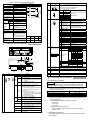
2.1 Performance specifications of the AJ65BT-R2
The AJ65BT-R2 performance specifications are shown below.
RS-232C specifications
CAUTION
When disposing of the product, handle it as industrial waste.
About Manuals
The following manuals are also related to this product.
In necessary, order them by quoting the details in the tables below.
RS-232C Interface Module Type AJ65BT-R2
User’s Manual
Manual Number
(Model Code)
IB-66781
(13JL24)
Related Manuals
Manual Name
Control & Communication Link System
Master/Local Module Type
AJ61BT11/A1SJ61BT11 User's Manual
Control & Communication Link System
Master/Local Module Type
AJ61QBT11/A1SJ61QBT11 User's Manual
CC-Link System Master/Local Module User's
Manual QJ61BT11N
Manual Number
(Model Code)
IB-66721
(13J872)
IB-66722
(13J873)
SH-080394E
(13JR64)
Please RS-232C Interface Module Type AJ65BT-R2 User’s Manual
before using this module
When incorporating the Mitsubishi PLC into other machinery or
equipment and keeping compliance with the EMC and low voltage
directives, refer to Chapter 3, "EMC Directives and Low Voltage
Directives" of the User's Manual (Hardware) included with the CPU
module or base unit used.
The CE logo is printed on the rating plate of the PLC, indicating
compliance with the EMC and low voltage directives.
To conform this product to the EMC Directive and Low Voltage Directive,
refer to the Section of "CC-Link Modules" in Chapter 3 "EMC Directive
and Low Voltage Directive" in the User’s Manual (Hardware) of the CPU
module used or the PLC CPU supplied with the base unit.
1. Overview
This manual explains the specifications, handling instructions, wiring of the
RS-232C Interface Module Type AJ65BT-R2 (hereinafter referred to as the
AJ65BT-R2), which is used as an intelligent device station in the CC-Link
system.
(1) Included product
After unpacking, confirm that the following is included.
Product name
RS-232C Interface Module Type AJ65BT-R2
300, 600, 1200, 2400, 4800, 9600, 19200bps
(Select with RS-232C transmission specification setting switch)
1
7/8
1 (Yes)/0 (No)
1/2
With parity check (even/odd)/None
DTR/DSR (ER/DR) control
DC1/DC3 control
15m
5120 bytes
Item
Performance specifications
General-purpose
Input side
: 24VDC (sink/source common type) 2 points
input/output
Output side : Transistor output (sink type) 12/24VDC 2 points
specifications
Terminal block (Refer to section 2.2)
Transmission path
Bus (RS-485)
EEPROM writing life
100,000 times
CC-Link station type
Intelligent device station
No. of occupied stations
1 station (RX/RY 32 points each, RWw/RWr 4 points each)
Connection cable
CC-Link dedicated cable
Withstand voltage
One minute at 500VAC between DC external terminal batch
and grounding
Insulation resistance
10M or more with 500VDC insulation resistance meter
between DC external terminal batch and grounding
Noise withstand level
DC type noise voltage 500Vp-p
With noise width 1 s, noise frequency 25 to 60Hz noise
simulator
Module installation
16mm or more screw
M4 0.7mm
screw
(Tightening torque range 0.78 to 1.18Nym)
DIN rail may also be used for mounting.
Applicable DIN rail
TH35-7.5Fe, TH35-7.5Al, TH35-15Fe (JIS C 2812 compliant)
External Power supply
24VDC
Current consumption: 0.11A
Tolerable instantaneous
1ms
power failure time
Weight
0.40kg
For the general specifications, refer to the RS-232C Interface Module Type
AJ65BT-R2 User’s Manual.
2.2 General-purpose input/output specifications
Compliance with the EMC/Low Voltage Directive
Model name
AJ65BT-R2
Data format Star bit
Data bit
Parity bit
Stop bit
Error detection
Communication control
(flow control)
Transmission distance
OS reception area
Performance specifications
RS-232C compliant, 1 channel (Refer to section 5.2)
Full duplex communication method
Start-stop synchronization method
Quantity
1
The general-purpose input/output specifications of the AJ65BT-R2 are
shown in Tables 2.1 and 2.2.
Table 2.1 General-purpose input specifications
DC input (sink, source common type)
AJ65BT-R2
External connection
No. of input points
Insulation method
Rated input
voltage
Rated input
current
Working voltage
range
Max. No. of
simultaneous
input points
ON voltage/ON
current
OFF voltage/OFF
current
Input resistance
Response OFF
time
ON
2 points
Photo coupler insulation
24VDC
Approx. 7mA
19.2 to 28.8VDC
(ripple rate within 5%)
100%
14V or more/3.5mA or more
1 XC
24VDC
2 COM1
Internal
circuit
Manual Name
Data link specifications
Detailed manual
Item
Interface specifications
Transmission method
Synchronization
method
Transmission speed
6V or less/1.7mA or less
3 XD
Approx. 3.3k
10ms or less
10ms or less
ON
OFF
Common method 2 points/common (COM1)
Sink, source common type
9-pin connector (I/O section)
External
7-point terminal block
connection
(M3.5 screw)
method
Including transmission circuit
and module power terminal
Applicable wire
0.75 to 2mm2
size
Applicable crimp RAV1.25-3.5, RAV2-3.5
terminal
(JIS C 2805 compliant)
Terminal Signal
No.
name
Terminal
No.
Signal
name
TB1
XC
TB3
XD
TB2
COM1
TB4
NC
Table 2.2 General-purpose output specifications
No.
Transistor output (sink type)
AJ65BT-R2
External connection
Surge killer
Common method
External connection
method
Applicable wire size
Applicable crimp
terminal
2 points
Photo coupler insulation
12/24VDC
10.2 to 28.8VDC
(ripple rate within 5%)
0.1A/point 0.2A/common
0.4A 10ms or less
0.1mA or less
switch
5 YC
L
(3) Data link transmission
12/24VDC
6 COM2
Internal
circuit
No. of output points
Insulation method
Rated load voltage
Working load voltage
range
Max. load current
Max. rush current
Leakage current at
OFF
Max. voltage drop at
ON
Output type
Response OFF ON
time
ON OFF
Output
Voltage
section
externally
Current
supplied
power
Name
(2) Station No. setting
speed setting switch
7 YD
L
1.5VDC or less (MAX) 0.1A
Sink type
2ms or less
(4) Mode setting switch
2ms or less (resistance load)
10.2 to 28.8VDC
(ripple rate within 5%)
50mA or less (TYP. 24VDC,
per common)
Not including external load
current.
Zener diode
2 points/common (COM2)
9-pin connector (I/O section)
7-point terminal block (M3.5
screw)
Including transmission circuit
and module power terminal
2
0.75 to 2mm
RAV1.25-3.5, RAV2-3.5 (JIS C
2805 compliant)
Terminal Signal Terminal Signal
No.
name
No.
name
TB5
YC
TB7
YD
TB6
COM2
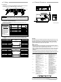
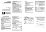
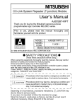
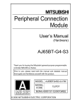
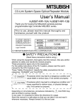
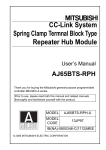
3. Part Names and Settings
(5) RS-232C
transmission
specifications setting
switch
(10)
(1)
(4) (3) (2)
(9)
(5)
(6) Data link terminal
block
(7) RS-232C interface
(8) General-purpose
(6)
No.
(7)
Name
(1) Operation display
LEDs
(8)
Details
LED name
Details
ON : Power is ON.
OFF : Power is OFF.
ON : Operating normally
Default RUN
OFF : Power (24VDC) is OFF or WDT error is
state
occurring.
ON : Communicating normally
L RUN OFF : Communication stopped (Time over
error)
ON : Any transmission speed or station
number out of range is set.
Flickering at constant intervals :
The transmission speed or station number
has been changed after the power is
State L ERR.
turned on.
Flickering not constant intervals :
The terminating resistor is not connected.
The module or CC-Link dedicated cable is
being affected by noise.
OFF: Communicating normally
ON : Data link Sending data
SD
OFF : Data link Not sending data
Others
ON : Data link Receiving data
RD
OFF : Data link Not receiving data
ON : General-purpose input (XC, XD) is ON.
XC, XD
OFF : General-purpose input (XC, XD) is OFF.
ON : General-purpose output (YC, YD) is ON.
YC, YD
OFF : General-purpose output (YC, YD) is OFF.
ON : Sending RS-232C data
RS-232-C SD
OFF : Not sending RS-232C data
ON : Receiving RS-232C data
RS-232-C RD
OFF : Not receiving RS-232C data
ON : RS-232C transmission error
RS-232-C ERR.
OFF : No error
PW
input/output terminal
block
(9) Reset switch
(10) Connector
Details
Set the module's station No. (Default setting: 0)
Setting range: 1 to 64 (0: Master module)
" 10" sets the 10th place of the station No..
" 1" sets the 1st place of the station No..
Transmission
speed
0
156kbps
Set the module's transmission speed
1
625kbps
(for data link)
2
2.5Mbps
(Default setting: 0)
3
5Mbps
4
10Mbps
5 to 9
Setting error
Set the module's operation state. (Default setting: 0)
No.
Name
Setting details
On-line mode
Mode for on-line communication.
0 (using transmission/ Set when using the
reception buffer)
transmission/reception buffer.
On-line mode
Mode for on-line communication.
(using buffer
1
Set when using the buffer memory
memory automatic
automatic update function.
update function)
2 Not used
Setting error ("RUN" LED turns OFF.)
3 Not used
Setting error ("RUN" LED turns OFF.)
4 Use not possible
–
5 Not used
Setting error ("RUN" LED turns OFF.)
6 Not used
Setting error ("RUN" LED turns OFF.)
7 Not used
Setting error ("RUN" LED turns OFF.)
8 Not used
Setting error ("RUN" LED turns OFF.)
9 Not used
Setting error ("RUN" LED turns OFF.)
A Not used
Setting error ("RUN" LED turns OFF.)
B Not used
Setting error ("RUN" LED turns OFF.)
C Not used
Setting error ("RUN" LED turns OFF.)
Hardware test
Mode for confirming that module runs
D
mode
independently.
E Not used
Setting error ("RUN" LED turns OFF.)
F Not used
Setting error ("RUN" LED turns OFF.)
Set the RS-232C transmission specifications.
Default
Setting switch state
No. Setting details
setting
ON
OFF
SW 1
2
3
0
0
0
300bps
1
0
0
600bps
0
1
0 1200bps
SW1 Transmission
1
1
0 2400bps
to 3 speed
OFF
0
0
1 4800bps
1
0
1 9600bps
0
1
1 19200bps
0:OFF
1:ON
SW4
Not used
SW5 Data bit length
8
7
ON
SW6
Yes
No
Parity bit
OFF
SW7
Even
Odd
SW8 Stop bit length
2
1
Connect a CC-Link dedicated cable for power supply and data
link. (2-piece terminal block)
Connect an RS-232C cable for connection with external device.
Connect the input/output wire.
Setting
Returns to the power ON status.
Use prohibited.
4. Mounting and Installation
4.1 Precautions for handling
POINT
For handling instructions such as module installation/removal, read
SAFETY PRECAUTIONS given at the beginning of this manual.
(1) Tighten the module installation screws and terminal block screws
within the following range.
Screw place
Module installation screw (M4 screw)
Terminal block terminal screw (M3.5 screw)
Terminal block installation screw (M4 screw)
Tightening torque range
0.78 to 1.18Nym
0.59 to 0.88Nym
0.98 to 1.37Nym
(2) When using the DIN rail adaptor, install the DIN rail while observing
the following points.
(a) Applicable DIN rail type (JIS C 2812 compliant)
TH35-7.5Fe
TH35-7.5Al
TH35-15Fe
(b) DIN rail installation screw pitch
When installing the DIN rail, tighten the screws at a pitch of
200mm or less.
4.2 Installation environment
When installing the PLC, refer to the CC-Link system master module's
User's Manual.
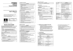
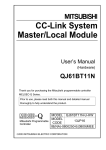
5. Wiring
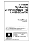
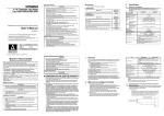
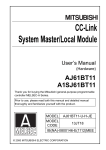
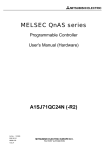
6. External Dimensions
9.5
(0.37)
5.1 Data Link
DB
(Y)
DG
SLD
FG
CC-Link dedicated
cable
DA
DB
DB
DG
DG
SLD
24V
Terminator
SLD
CC-Link dedicated
cable
24V
24G
24G
FG
FG
2-φ4.5 installation hole
POINT
Always connect the modules on both ends of the data link with the
"terminator" enclosed with the master module. (Connect across DA-DB)
4.5
(0.18)
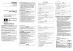
5.2 Connection with external device
4.5
(0.18)
Terminator
DA
(W)
71 (2.79)
80 (3.14)
(B)
DA
Remote module
AJ65BT-R2
Master module
63.5 (2.50)
The method of connecting the AJ65BT-R2, master module and remote
module with a CC-Link dedicated cable is shown below.
161 (6.33)
170 (6.68)
The method of connecting the AJ65BT-R2 and external device with
RS-232C is show below.
1
2
6
3
7
4
8
5
9
Pin
No.
1
The following type of
connector is mounted on
the AJ65BT-R2 side, so
use a mate connector
that matches this type.
9-pin D-SUB (female)
screw-fixed type
DDK Ltd.
17L-10090-27-D9AC
2
3
4
5
6
7
8
9
Name
Reception carrier
detection
Reception data
Transmission data
Data terminal ready
Signal ground
Data set ready
Transmission request
Transmission enable
Not used
Signal
abbrev.
Unit: mm (inch)
Signal direction
AJ65BT-R2
external device
CD
RD(RXD)
SD(TXD)
ER(DTR)
SG
DR(DSR)
RS(RTS)
CS(CTS)
–
–
Figure 5.1 RS-232C interface specifications
(1) Example of connection for DC code control and DTR/DSR signal
control
AJ65BT-R2 side (DTE)
Signal abbrev.
Pin No.
SD
3
RD
2
RS
7
CS
8
DR
6
SG
5
CD
1
ER
4
Cable connection and signal
method
External device (DTE)
Signal abbrev.
SD
RD
RS
CS
DR
SG
CD
ER
(2) Example of connection for only DC code control
AJ65BT-R2 side (DTE)
Signal abbrev.
Pin No.
SD
3
RD
2
RS
7
CS
8
DR
6
SG
5
CD
1
ER
4
Cable connection and signal
method
External device (DTE)
Signal abbrev.
SD
RD
RS
CS
DR
SG
CD
ER
Warranty
Mitsubishi will not be held liable for damage caused by factors found not to be
the cause of Mitsubishi; machine damage or lost profits caused by faults in the
Mitsubishi products; damage, secondary damage, accident compensation
caused by special factors unpredictable by Mitsubishi; damages to products
other than Mitsubishi products; and to other duties.
For safe use
y This product has been manufactured as a general-purpose part for general
industries, and has not been designed or manufactured to be incorporated in a
device or system used in purposes related to human life.
y Before using the product for special purposes such as nuclear power, electric
power, aerospace, medicine or passenger movement vehicles, consult with
Mitsubishi.
y This product has been manufactured under strict quality control. However,
when installing the product where major accidents or losses could occur if the
product fails, install appropriate backup or failsafe functions in the system.
Country/Region Sales office/Tel
Country/Region Sales office/Tel
Hong Kong
Mitsubishi Electric Automation
U.S.A
Mitsubishi Electric Automation Inc.
(Hong Kong) Ltd.
500 Corporate Woods Parkway Vernon
10th Floor, Manulife Tower, 169 Electric
Hills, IL 60061, U.S.A.
Road, North Point, Hong Kong
Tel : +1-847-478-2100
Tel : +852-2887-8870
Brazil
MELCO-TEC Rep. Com.e Assessoria
China
Mitsubishi Electric Automation
Tecnica Ltda.
(Shanghai) Ltd.
Rua Correia Dias, 184,
4/F Zhi Fu Plazz, No.80 Xin Chang Road,
Edificio Paraiso Trade Center-8 andar
Shanghai 200003, China
Paraiso, Sao Paulo, SP Brazil
Tel : +86-21-6120-0808
Tel : +55-11-5908-8331
Taiwan
Setsuyo Enterprise Co., Ltd.
Germany
Mitsubishi Electric Europe B.V. German
6F No.105 Wu-Kung 3rd.Rd, Wu-Ku
Branch
Hsiang, Taipei Hsine, Taiwan
Gothaer Strasse 8 D-40880 Ratingen,
Tel : +886-2-2299-2499
GERMANY
Korea
Mitsubishi Electric Automation Korea
Co., Ltd.
Tel : +49-2102-486-0
1480-6, Gayang-dong, Gangseo-ku
U.K
Mitsubishi Electric Europe B.V. UK
Seoul 157-200, Korea
Branch
Tel : +82-2-3660-9552
Travellers Lane, Hatfield, Hertfordshire.,
Singapore
Mitsubishi
Electric Asia Pte, Ltd.
AL10 8XB, U.K.
307 Alexandra Road #05-01/02,
Tel : +44-1707-276100
Mitsubishi Electric Building,
Italy
Mitsubishi Electric Europe B.V. Italian
Singapore 159943
Branch
Tel : +65-6470-2460
Centro Dir. Colleoni, Pal. Perseo-Ingr.2
Thailand
Mitsubishi Electric Automation (Thailand)
Via Paracelso 12, I-20041 Agrate Brianza.,
Co., Ltd.
Milano, Italy
Bang-Chan Industrial Estate No.111
Tel : +39-039-60531
Moo 4, Serithai Rd, T.Kannayao,
Spain
Mitsubishi Electric Europe B.V. Spanish
A.Kannayao, Bangkok 10230 Thailand
Tel : +66-2-517-1326
Branch
Indonesia
P.T. Autoteknindo Sumber Makmur
Carretera de Rubi 76-80,
Muara Karang Selatan, Block A/Utara
E-08190 Sant Cugat del Valles,
No.1 Kav. No.11 Kawasan Industri
Barcelona, Spain
Pergudangan Jakarta - Utara 14440,
Tel : +34-93-565-3131
P.O.Box 5045 Jakarta, 11050 Indonesia
France
Mitsubishi Electric Europe B.V. French
Tel : +62-21-6630833
Branch
India
Messung Systems Pvt, Ltd.
25, Boulevard des Bouvets, F-92741
Electronic Sadan NO:III Unit No15,
Nanterre Cedex, France
M.I.D.C Bhosari, Pune-411026, India
TEL: +33-1-5568-5568
Tel : +91-20-2712-3130
South Africa
Circuit Breaker Industries Ltd.
Australia
Mitsubishi Electric Australia Pty. Ltd.
Private Bag 2016, ZA-1600 Isando,
348 Victoria Road, Rydalmere,
South Africa
N.S.W 2116, Australia
Tel : +27-11-928-2000
Tel : +61-2-9684-7777
HEAD OFFICE : TOKYO BUILDING, 2-7-3 MARUNOUCHI, CHIYODA-KU, TOKYO 100-8310, JAPAN
NAGOYA WORKS : 1-14, YADA-MINAMI 5-CHOME, HIGASHI-KU, NAGOYA, JAPAN
When exported from Japan, this manual does not require application to the Ministry
of Economy, Trade and Industry for service transaction permission.
Specifications subject to change without notice.
Printed in Japan on recycled paper.