1
[Installation Precautions]
AJ65BT-68TD
Thermocouple
Temperature Input Module
Mitsubishi General-Purpose Programmable Controller
User’s Manual
(Hardware)
Thank you for purchasing the Mitsubishi general-purpose
programmable controller MELSEC-A series.
Prior to use, please read this manual thoroughly and
familiarize yourself with the product.
Type
AJ65BT68TD-U-HW-E
Type
13JL49
Code
IB(NA)-66830-H(1112)MEE
C
CAUTION
• Use the programmable controller in an environment that meets the general
specifications in this manual.
Failure to do so may result in electric shock, fire, malfunction, or damage to
or deterioration of the product.
• For protection of the switches, do not remove the cushioning material before
installation.
• Securely fix the module with a DIN rail or mounting screws. Tighten the
screws within the specified torque range.
Undertightening can cause drop of the screw, short circuit or malfunction.
Overtightening can damage the screw and/or module, resulting in drop,
short circuit, or malfunction.
• Do not directly touch any conductive part of the module.
Doing so can cause malfunction or failure of the module.
[Wiring Precautions]
CAUTION
• Shut off the external power supply for the system in all phases before wiring.
Failure to do so may result in damage to the product.
• After installation or wiring, attach the included terminal cover to the module
before turning it on for operation.
Undertightening can cause short circuit or malfunction.
• Ground the FG terminals to the protective ground conductor dedicated to the
programmable controller.
Failure to do so may result in malfunction.
• Use applicable solderless terminals and tighten them within the specified
torque range. If any spade solderless terminal is used, it may be disconnected
when the terminal screw comes loose, resulting in failure.
• Check the rated voltage and terminal layout before wiring to the module, and
connect the cables correctly.
Connecting a power supply with a different voltage rating or incorrect wiring
may cause a fire or failure.
• Tighten the terminal screw within the specified torque range.
Undertightening can cause short circuit or malfunction.
Overtightening can damage the screw and/or module, resulting in drop, short
circuit, or malfunction.
• Prevent foreign matter such as dust or wire chips from entering the module.
Such foreign matter can cause a fire, failure, or malfunction.
1996 MITSUBISHI ELECTRIC CORPORATION
SAFETY PRECAUTIONS
(Read these precautions before using this product.)
Before using this product, please read this manual and the relevant manuals carefully
and pay full attention to safety to handle the product correctly.
These precautions apply only to Mitsubishi equipment. Refer to the CPU module
user’s manual for a description of the programmable controller system safety
precautions.
In this manual, the safety precautions are classified into two levels: "
WARNING "
and "
CAUTION".
WARNING
Indicates that incorrect handling may cause hazardous
conditions, resulting in death or severe injury.
CAUTION
Indicates that incorrect handling may cause hazardous
conditions, resulting in minor or moderate injury or
property damage.
Under some circumstances, failure to observe the precautions given under "
CAUTION" may lead to serious consequences.
Observe the precautions of both levels because they are important for personal and
system safety.
Make sure that the end users read this manual and then keep the manual in a safe
place for future reference.
[Design Precautions]
WARNING
• In the case of a communication failure in the network, data in the master
module are held.
Check the communication status information (SB, SW) and configure an
interlock circuit in the sequence program to ensure that the entire system
will operate safely.
CAUTION
• Do not install the control lines or communication cables together with the
main circuit lines or power cables.
Keep a distance of 100mm (3.94 inches) or more between them.
Failure to do so may result in malfunction due to noise.
[Wiring Precautions]
CAUTION
• Place the cables in a duct or clamp them.
If not, dangling cable may swing or inadvertently be pulled, resulting in
damage to the module or cables or malfunction due to poor contact.
• Do not install the control lines or communication cables together with the main
circuit lines or power cables. Failure to do so may result in malfunction due to
noise.
• When disconnecting the cable from the module, do not pull the cable by the
cable part. Loosen the screws of connector before disconnecting the cable.
Failure to do so may result in damage to the module or cable or malfunction
due to poor contact.
[Starting and Maintenance Precautions]
CAUTION
• Do not touch any terminal while power is on.
Doing so may cause malfunction.
• Shut off the external power supply for the system in all phases before cleaning
the module or retightening the terminal screws.
Failure to do so may cause the module to fail or malfunction.
Undertightening the terminal screws can cause short circuit or malfunction.
Overtightening can damage the screw and/or module, resulting in drop, short
circuit, or malfunction.
• Do not disassemble or modify the module.
Doing so may cause failure, malfunction, injury or a fire.
• Do not drop or apply any strong shock to the module.
Doing so may damage the module.
• Shut off the external power supply for the system in all phases before mounting
or removing the module to or from the panel.
Failure to do so may cause the module to fail or malfunction.
• Mounting/removing the terminal block is limited to 50 times after using a
product. (IEC61131-2 compliant)
• Before handling the module, touch a grounded metal object to discharge the
static electricity from the human body.
Failure to do so may cause the module to fail or malfunction.
[Disposal Precautions]
CAUTION
• When disposing of this product, treat it as industrial waste
z CONDITIONS OF USE FOR THE PRODUCT z
(1) Mitsubishi programmable controller ("the PRODUCT") shall be used in
conditions;
i) where any problem, fault or failure occurring in the PRODUCT, if
any, shall not lead to any major or serious accident; and
ii) where the backup and fail-safe function are systematically or
automatically provided outside of the PRODUCT for the case of any
problem, fault or failure occurring in the PRODUCT.
(2) The PRODUCT has been designed and manufactured for the purpose of
being used in general industries.
MITSUBISHI SHALL HAVE NO RESPONSIBILITY OR LIABILITY
(INCLUDING, BUT NOT LIMITED TO ANY AND ALL RESPONSIBILITY
OR LIABILITY BASED ON CONTRACT, WARRANTY, TORT, PRODUCT
LIABILITY) FOR ANY INJURY OR DEATH TO PERSONS OR LOSS OR
DAMAGE TO PROPERTY CAUSED BY the PRODUCT THAT ARE
OPERATED OR USED IN APPLICATION NOT INTENDED OR EXCLUDED
BY INSTRUCTIONS, PRECAUTIONS, OR WARNING CONTAINED IN
MITSUBISHI'S USER, INSTRUCTION AND/OR SAFETY MANUALS,
TECHNICAL BULLETINS AND GUIDELINES FOR the PRODUCT.
("Prohibited Application")
Prohibited Applications include, but not limited to, the use of the PRODUCT in;
y Nuclear Power Plants and any other power plants operated by Power
companies, and/or any other cases in which the public could be affected if
any problem or fault occurs in the PRODUCT.
y Railway companies or Public service purposes, and/or any other cases in
which establishment of a special quality assurance system is required by
the Purchaser or End User.
y Aircraft or Aerospace, Medical applications, Train equipment, transport
equipment such as Elevator and Escalator, Incineration and Fuel devices,
Vehicles, Manned transportation, Equipment for Recreation and Amusement,
and Safety devices, handling of Nuclear or Hazardous Materials or
Chemicals, Mining and Drilling, and/or other applications where there is a
significant risk of injury to the public or property.
Notwithstanding the above, restrictions Mitsubishi may in its sole discretion,
authorize use of the PRODUCT in one or more of the Prohibited
Applications, provided that the usage of the PRODUCT is limited only for the
specific applications agreed to by Mitsubishi and provided further that no
special quality assurance or fail-safe, redundant or other safety features
which exceed the general specifications of the PRODUCTs are required. For
details, please contact the Mitsubishi representative in your region.
About Manuals
The following are manuals related to this product.
Request for the manuals as needed according to the chart below.
Detailed Manual
Manual Name
AJ65BT-68TD Thermocouple Temperature Input Module User's
Manual
Manual No.
(Model Code)
SH-3304
(13JL52)
Related Manuals
Manual Name
CC-Link System Master/Local Module Type AJ61BT11/A1SJ61BT11
User's Manual
CC-Link System Master/Local Module Type
AJ61QBT11/A1SJ61QBT11 User's Manual
CC-Link System Master/Local Module User's Manual
Type AnSHCPU/AnACPU/AnUCPU/QCPU-A (A Mode) Programming
Manual (Dedicated Instructions)
MELSEC-L CC-Link System Master/Local Module User's Manual
Manual No.
(Model Code)
IB-66721
(13J872)
IB-66722
(13J873)
SH-080394
(13JR64)
IB-66251
(13J742)
SH-080895ENG
(13JZ41)
2. EMC and Low Voltage Commands
(1) Method of ensuring compliance
To ensure that Mitsubishi programmable controllers maintain
EMC and Low Voltage Directives when incorporated into other
machinery or equipment, certain measures may be necessary.
Please refer to one of the following manuals.
y User's manual for the CPU module or head module used
y Safety Guidelines (this manual is included with the CPU
module, base unit, or head module)
The CE mark on the side of the programmable controller
indicates compliance with EMC and Low Voltage Directives.
(2) Additional measures
To ensure that this product maintains EMC and Low Voltage
Directives, please refer to one of the manuals listed under (1).
B
600 to 1700
16-bit signed binary (–2000 to 17000 : value to one decimal
place multiplied by 10)
Scaling value
16-bit signed binary (0 to 2000)
Applicable thermocouples and
temperature measurement
range accuracy *1
± 1.0°C
B, R, S : 0.3 °C
Number of occupied stations
Connection cable
Noise durability
Dielectric withstand voltage
Insulation method
Insulation resistor
Connected terminal block
Applicable wire size
Applicable solderless terminal
Module mounting screw
Applicable DIN rail
External power supply
Internal consumption current
Allowable momentary power
failure period
Weight
± 0.4 °C
6.1
± 0.3 °C
– 200 to 0
±0.06 °C or ±0.3 % of the measured
temperature, whichever is greater
0 to 1200
±0.06 °C or ±0.02 % of the
measured temperature, whichever
is greater
– 200 to 0
±0.06 °C or ±0.3 % of the measured
temperature, whichever is greater
J
DA
6.2
±5V
SW
0
1-8
9
8-channel + Pt 100 connection channel
Remote device station
MODE
NORMAL
TEST CH.
TEST
01
2
3
4
901
8
2
7
3
654
RESET
6)
GAIN DOWN
5)
4 Stations : RX/RY 128 points each
RWw/RWr 16 points each
6.3
CC-Link dedicated cable
Depends on noise simulator of noise voltage at 500Vp-p,
noise width at 1ms and noise frequency at 25 to 60 Hz
8)
Between batch power supply system and ground
Between batch power supply system and batch
communication system
Between batch communication system and batch
thermocouple input
Between batch thermocouple input and ground
500 V AC, 1 minute
Number
1)
2)
3)
4)
5)
6)
Thermocouple input to CC-Link transmission
: Transfer insulation
Between channels
: Transfer insulation
Between batch power supply system and ground
Between batch power supply system and batch
communication system
Between batch communication system and batch
thermocouple input
Between batch thermocouple input and ground
500 V DC, more than 10 M Ω by the insulation resistance
taster
27-point terminal blocks (M3.5 × 7 screws)
0.75 to 2.00 mm2
RAV1.25-3.5, RAV2-3.5 (Conforms to JIS C 2805)
Screws M4 × 0.7 mm × 16 mm or larger (tightening torque range
78 to 118 N • cm {8 to 12 kg • cm})
May be attached using DIN rails
TH 35-7.5 Fe, TH 35-7.5 Al, TH 35-15 Fe
(conform to JIS C 2812)
24 V DC (18 to 30 V DC)
0.081 A (at 24VDC)
1 ms
0.40 (0.88) kg (lb.)
*1 : The thermocouple type can be set using the remote register
RY (n + 1) 0 to RY (n + 5) 6 for each channel.
7)
8)
9)
7) 3) 4)
(White)
9.5
(0.37)
01
901
2 8
2
3 7
3
654
654
SET
GAIN DOWN
RESET
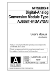
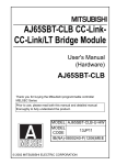
142.9(5.63)
(White)
(Yellow)
DA
DB
DG
(Blue)
(White)
(White)
(Yellow)
(Yellow)
SLD
CC-Link
dedicated cable
I/O module, etc.
(Blue)
CC-Link
dedicated cable
FG
DA
Unit: mm (in.)
DB
DG
Terminal
resistor
SLD
FG
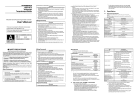
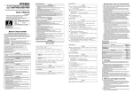
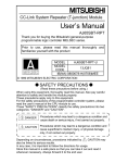
Precautions when Wiring
Example of Connecting Module
The following shows the wiring example between AJ65BT-68TD and
thermocouple.
9)
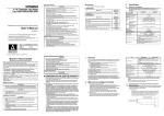
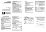
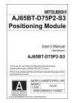
Name
Station setting switch
Transmission baud rate setting switch
Mode switch
Offset/gain setting switch
UP/DOWN switch
Reset switch
PW
RUN
L RUN
LED display
SD
RD
L ERR.
Terminal block
Temperature-measuring resistor Pt 100
RTD
Input
amplifier
Pt100
CH1
+
-
5. Handling
5.1
(Blue)
(2) Always place a thermocouple at least 10 cm (3.94 in.) apart from the
main circuit line and AC control circuit line. Place a thermocouple
sufficiently apart from circuits with high frequency, such as highvoltage lines and inverter load main circuits. If they are placed close
to each other, the thermocouple is influenced more easily by the
noise, surge, or conductivity.
01
901
2 8
2
3 7
3
654
654
SET
901
8
2
7
3
654
(1) Use separate cables for the AC and the external input signals of the
AJ65BT-68TD, in order not to be affected by the AC side surge or
conductivity.
1)
MODE OFFSET UP
01
2
3
4
MODE OFFSET UP
To obtain maximum performance from the functions of AJ65BT-68TD and
improve the system reliability, a wiring with high durability against noise is
required.
The following describes the external wiring precautions.
B RATE STATION NO.
X10
X1
PW
RUN
L RUN
SD
RD
L ERR.
PW
RUN
L RUN
SD
RD
L ERR.
Point
K, E, J, T : 0.1 °C
MELSEC A J65BT-68TD
MODE
NORMAL
TEST CH.
TEST
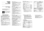
For the modules at both ends of the data link, make sure to connect the "terminal
resistor" that is attached to a master module (connect between DA and DB).
The name of each part in the AJ65BT-68TD is described.
MITSUBISHI
(Blue)
FG
4. Name of Each Part
2)
AJ65BT-68TD
Master module
Terminal
(Yellow)
DG
resistor
SLD
±0.06 °C or ±0.02 % of the
measured temperature, whichever
is greater
0 to 350
SW
0
1-8
9
Wiring Example with Each CC-Link Modules
DB
±0.06 °C or ±0.3 % of the measured
temperature, whichever is greater
– 200 to 0
T
B RATE STATION NO.
X10
X1
MELSEC AJ65BT-68TD
151.9 (5.98)
±0.5 °C or ±0.25 % of ±0.06 °C or ±0.02 % of the
the measured
measured temperature, whichever
temperature, whichever is greater
is greater
±0.06 °C or ±0.02 % of the
measured temperature, whichever
is greater
0 to 750
MITSUBISHI
The following shows the connection between the AJ65BT-68TD and
master module using twisted cables.
200 to 1600
0 to 800
2- ø4.5 installing hole
6. Wiring
± 2.0 °C
E
45 ms/ch
Absolute maximum input
CC-Link station type
0 to 200
By the calculation of *2
Conversion speed
(sampling time)
Number of analog input points
± 0.3 °C
NP
When installing a DIN rail, tighten the screws with a space of less than
200 mm (7.9 in.).
Refer to Table 3.1
Cold junction compensation
accuracy
Maximum resolution
(5) When using a DIN rail adapter, install the DIN rail considering the
precautions described below.
± 0.4 °C
200 to 1600
–200 to 1700°C
Detected
temperature
0.98 to 1.37 N · m
TH 35-7.5 Fe
TH 35-7.5 Al
TH 35-15 Fe
(b) Space between DIN rail mounting screws
± 0.4 °C
S
Specification
Temperature sensor input
Terminal block mounting screws (M3.5 screw)
Temperature characteristic
(Per 1 °C of ambient operating
temperature change)
± 2.5 °C
K
Item
0.78 to 1.18 N · m
0.59 to 0.88 N · m
(a) Applicable DIN rail types (conform to JIS C 2812)
± 2.0 °C
Performance Specification
Overall accuracy
Conversion accuracy
(When ambient
operating 25 ± 5 °C)
0 to 200
The performance specification of the AJ65BT-68TD are shown
below.
And, refer to master module user's manual which is used about the
general specification.
Output
Temperature
measurement
range [°C ]
R
3. Specification
3.1
Module mounting screws (M4 screw)
Terminal block terminal screws (M3.5 screw)
Table 3.1 Applicable thermocouples and temperature measurement range
accuracy
Applicable
thermocouple
type
7. External Dimensions Diagram
Tightening torque range
56 (2.2)
The AJ65BT-68TD is a module that converts the thermocouple input
values from outside the programmable controller to the temperature
values or scaling values of 16-bit signed BIN data.
Screw area
65 (2.56)
This user's manual explains the specifications, handling, programming
methods, etc. of the AJ65BT-68TD Thermocouple Input Module
(hereinafter referred to as AJ65BT-68TD) used as a remote device
station for the CC-Link system.
63 (2.48)
*2 : Overall accuracy computation method is as follows:
(Overall accuracy) = (Conversion accuracy) + (Temperature characteristics) ×
(Ambient operating temperature change) + (Cold junction compensation
accuracy)
The ambient operating temperature change refers to the value that falls
outside the range of 25 ±5 °C.
Example) The overall accuracy when using thermocouple K, measured
temperature 150 °C, ambient operating temperature 35 °C will be:
(± 0.5 °C) + (± 0.06 °C) × (5 °C) + (± 1 °C) = ± 1.8 °C
1. Overview
CH8
+
-
Handling Precautions
Filter
Input
amplifier
Transformer
Filter
Input
amplifier
Transformer
(1) Because it is made of resin, do not drop or given a strong shock to
the module case and the terminal block.
(2) Do not take the printed circuit board of the module out of the case.
may result in a failure.
It
(3) Be careful not to let foreign matter such as filings or wire chips get
inside the module while wiring. Remove all foreign matters if any get
inside.
(4) Tighten the module mounting screws within the following torque
range.
*1
*2
*1 Be sure to use the shielded compensating conductor for the cable.
*2 Be sure to ground.
WARRANTY
Mitsubishi will not be held liable for damage caused by factors found not to be the cause of Mitsubishi;
machine damage or lost profits caused by faults in the Mitsubishi products; damage, secondary damage,
accident compensation caused by special factors unpredictable by Mitsubishi; damages to products other
than Mitsubishi products; and to other duties.