1
DISPEL: Data-Intensive Systems Process
Engineering Language
User’s Manual
Updated 22/8/11
Language and Architecture Team
The ADMIRE Project
www.admire-project.eu
Funded by the European Commission
(Framework 7 ICT 215024)
Contents
1 Introduction
1.1 Anatomy of a DISPEL Script . . . . . . . . . . . . . . . . . . . .
1.2 Core Components . . . . . . . . . . . . . . . . . . . . . . . . . . .
1.3 DISPEL Scripting . . . . . . . . . . . . . . . . . . . . . . . . . . .
1
1
4
5
2 Workflow Composition and Enactment
2.1 Processing Elements . . . . . . . . . . . . . . . . .
2.1.1 Processing Element Characteristics . . . . .
2.1.2 Processing Element Instances . . . . . . . .
2.1.3 Defining New Types of Processing Element
2.1.4 Connection Interfaces . . . . . . . . . . . .
2.1.5 Connection Modifiers . . . . . . . . . . . .
2.1.6 Processing Element Properties . . . . . . .
2.2 Data Streams . . . . . . . . . . . . . . . . . . . . .
2.2.1 Connections . . . . . . . . . . . . . . . . . .
2.2.2 Stream Literals . . . . . . . . . . . . . . . .
2.3 Registration and Enactment . . . . . . . . . . . . .
2.3.1 Exporting to the Registry . . . . . . . . . .
2.3.2 Importing from the Registry . . . . . . . .
2.3.3 Packaging . . . . . . . . . . . . . . . . . . .
2.3.4 Workflow Submission . . . . . . . . . . . .
2.3.5 Processing Element Termination . . . . . .
.
.
.
.
.
.
.
.
.
.
.
.
.
.
.
.
.
.
.
.
.
.
.
.
.
.
.
.
.
.
.
.
.
.
.
.
.
.
.
.
.
.
.
.
.
.
.
.
.
.
.
.
.
.
.
.
.
.
.
.
.
.
.
.
.
.
.
.
.
.
.
.
.
.
.
.
.
.
.
.
.
.
.
.
.
.
.
.
.
.
.
.
.
.
.
.
.
.
.
.
.
.
.
.
.
.
.
.
.
.
.
.
.
.
.
.
.
.
.
.
.
.
.
.
.
.
.
.
8
9
9
11
12
13
14
17
18
18
21
23
24
25
26
26
27
3 The DISPEL Type System
3.1 Language Types . . . . . . . . . . . .
3.1.1 Base Types . . . . . . . . . . .
3.1.2 Arrays . . . . . . . . . . . . . .
3.1.3 Tuples . . . . . . . . . . . . . .
3.1.4 Processing Elements . . . . . .
3.1.5 DISPEL Functions . . . . . . .
3.1.6 Processing Element Subtyping
3.2 Structural Types . . . . . . . . . . . .
3.2.1 Streaming Structured Data . .
3.2.2 Lists . . . . . . . . . . . . . . .
3.2.3 Arrays . . . . . . . . . . . . . .
3.2.4 Tuples . . . . . . . . . . . . . .
3.2.5 Partial Descriptions . . . . . .
.
.
.
.
.
.
.
.
.
.
.
.
.
.
.
.
.
.
.
.
.
.
.
.
.
.
.
.
.
.
.
.
.
.
.
.
.
.
.
.
.
.
.
.
.
.
.
.
.
.
.
.
.
.
.
.
.
.
.
.
.
.
.
.
.
.
.
.
.
.
.
.
.
.
.
.
.
.
.
.
.
.
.
.
.
.
.
.
.
.
.
.
.
.
.
.
.
.
.
.
.
.
.
.
29
30
31
31
32
32
34
35
37
37
38
39
39
40
i
.
.
.
.
.
.
.
.
.
.
.
.
.
.
.
.
.
.
.
.
.
.
.
.
.
.
.
.
.
.
.
.
.
.
.
.
.
.
.
.
.
.
.
.
.
.
.
.
.
.
.
.
.
.
.
.
.
.
.
.
.
.
.
.
.
.
.
.
.
.
.
.
.
.
.
.
.
.
.
.
.
.
.
.
.
.
.
.
.
.
.
.
.
.
.
.
.
.
.
.
.
.
.
.
.
.
.
.
.
.
.
.
.
.
.
.
.
.
.
.
.
.
.
.
.
.
.
.
.
.
.
.
.
.
.
.
.
.
.
.
.
.
.
.
.
41
41
42
42
43
44
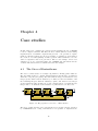
4 Case studies
4.1 The Sieve of Eratosthenes . . . . . . . . . . . . . .
4.2 k-fold Cross Validation . . . . . . . . . . . . . . . .
4.2.1 Constructing a k-fold cross validator . . . .
4.2.2 Producing data folds for the cross validator
4.2.3 Training and evaluating classifiers . . . . .
.
.
.
.
.
.
.
.
.
.
.
.
.
.
.
.
.
.
.
.
.
.
.
.
.
.
.
.
.
.
.
.
.
.
.
.
.
.
.
.
46
46
50
50
53
54
5 Language Reference
5.1 Control Constructs . . . . . . . . . .
5.1.1 Conditionals (if and switch)
5.1.2 Iterators (for and while) . .
5.2 Connection Modifiers . . . . . . . . .
5.2.1 after . . . . . . . . . . . . .
5.2.2 compressed . . . . . . . . . .
5.2.3 default . . . . . . . . . . . .
5.2.4 encrypted . . . . . . . . . .
5.2.5 initiator . . . . . . . . . .
5.2.6 limit . . . . . . . . . . . . .
5.2.7 locator . . . . . . . . . . . .
5.2.8 lockstep . . . . . . . . . . .
5.2.9 permutable . . . . . . . . . .
5.2.10 preserved . . . . . . . . . .
5.2.11 requiresDtype . . . . . . . .
5.2.12 requiresStype . . . . . . . .
5.2.13 roundrobin . . . . . . . . . .
5.2.14 successive . . . . . . . . . .
5.2.15 terminator . . . . . . . . . .
5.3 Processing Element Properties . . .
5.3.1 lockstep . . . . . . . . . . .
5.3.2 permutable . . . . . . . . . .
5.3.3 roundrobin . . . . . . . . . .
5.4 Reserved Operators and Keywords .
.
.
.
.
.
.
.
.
.
.
.
.
.
.
.
.
.
.
.
.
.
.
.
.
.
.
.
.
.
.
.
.
.
.
.
.
.
.
.
.
.
.
.
.
.
.
.
.
.
.
.
.
.
.
.
.
.
.
.
.
.
.
.
.
.
.
.
.
.
.
.
.
.
.
.
.
.
.
.
.
.
.
.
.
.
.
.
.
.
.
.
.
.
.
.
.
.
.
.
.
.
.
.
.
.
.
.
.
.
.
.
.
.
.
.
.
.
.
.
.
.
.
.
.
.
.
.
.
.
.
.
.
.
.
.
.
.
.
.
.
.
.
.
.
.
.
.
.
.
.
.
.
.
.
.
.
.
.
.
.
.
.
.
.
.
.
.
.
.
.
.
.
.
.
.
.
.
.
.
.
.
.
.
.
.
.
.
.
.
.
.
.
56
56
56
57
59
59
59
60
60
61
61
62
62
62
63
63
63
64
64
64
65
65
65
66
66
3.3
3.2.6 Defining Custom Structural Types
3.2.7 Structural Subtyping . . . . . . . .
Domain Types . . . . . . . . . . . . . . .
3.3.1 Domain type Namespaces . . . . .
3.3.2 Defining Custom Domain Types .
3.3.3 Domain Subtyping . . . . . . . . .
ii
.
.
.
.
.
.
.
.
.
.
.
.
.
.
.
.
.
.
.
.
.
.
.
.
.
.
.
.
.
.
.
.
.
.
.
.
.
.
.
.
.
.
.
.
.
.
.
.
.
.
.
.
.
.
.
.
.
.
.
.
.
.
.
.
.
.
.
.
.
.
.
.
.
.
.
.
.
.
.
.
.
.
.
.
.
.
.
.
.
.
.
.
.
.
.
.
.
.
.
.
.
.
.
.
.
.
.
.
.
.
.
.
.
.
.
.
.
.
.
.
.
.
.
.
.
.
.
.
.
.
.
.
.
.
.
.
.
.
.
.
.
.
.
.
.
.
.
.
.
.
.
.
.
.
.
.
.
.
.
.
.
.
.
.
.
.
.
.
.
.
.
.
.
.
.
.
.
.
.
.
.
.
.
.
.
.
.
.
.
.
.
.
.
.
.
.
.
.
.
.
.
.
.
.
.
.
.
.
.
.
.
.
.
.
.
.
Chapter 1
Introduction
The Data-Intensive Systems Process Engineering Language DISPEL is a highlevel scripting language used to describe abstract workflows for distributed dataintensive applications. These workflows are compositions of processing elements
representing knowledge discovery activities (such as batch database querying,
noise filtering and data aggregation) through which significant volumes of data
can be streamed in order to manufacture a useful knowledge artefact. Such
processing elements may themselves be defined by compositions of other, more
fundamental computational elements, in essense having their own internal workflows. Users can construct workflows using existing processing elements, or can
define their own, recording them in a registry for later use by themselves or
others.
DISPEL is based on a streaming-data execution model used to generate dataflow graphs which can be mapped onto computational resources hidden behind
designated gateways. These gateways construct, validate, optimise and execute
concrete distributed workflows which implement submitted DISPEL specifications. A gateway may have numerous means to implement the same abstract
workflow under different circumstances, but this is hidden from the average user
who instead selects processing elements based on well-defined logical specifications. Thus workflows can be constructed without particular knowledge of the
specific context in which they are to be executed, granting them greater generic
applicability.
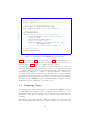
1.1
Anatomy of a DISPEL Script
DISPEL uses a notation similar to that of Java — a summary of DISPEL syntax
is provided in §1.3. There are generally two types of DISPEL script; scripts
which define and register new workflow elements, and scripts which construct
and submit workflows for execution. It is possible to define and use workflow
elements within the same script, but generally a user would want to register
once and use many times, leading to a natural division of code.
1
1
2
3
4
5
package dispel.manual {
// Import existing PE from the registry and define domain namespace.
use dispel.db.SQLQuery;
namespace db
"http://dispel-lang.org/resource/dispel/db";
6
// Define new PE type.
Type SQLToTupleList is
PE( <Connection:String::"db:SQLQuery"
expression> =>
<Connection:[<rest>]::"db:TupleRowSet" data> );
7
8
9
10
11
// Define new PE function.
PE<SQLToTupleList> lockSQLDataSource(String dataSource) {
SQLQuery sqlq = new SQLQuery;
|- repeat enough of dataSource -| => sqlq.source;
return PE( <Connection expression = sqlq.expression> =>
<Connection data
= sqlq.data> );
}
12
13
14
15
16
17
18
19
// Create new PEs.
PE<SQLToTupleList> SQLOnA = lockSQLDataSource("uk.org.UoE.dbA");
PE<SQLToTupleList> SQLOnB = lockSQLDataSource("uk.org.UoE.dbB");
20
21
22
23
// Register new entities (dependent entities will be registered as well).
register SQLOnA, SQLOnB;
24
25
26
}
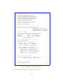
Figure 1.1: A DISPEL script which constructs a new workflow element.
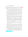
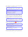
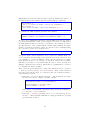
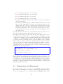
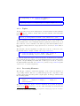
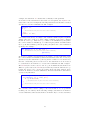
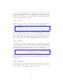
Figure 1.1 demonstrates the four main stages in constructing and registering
new workflow elements:
• The definition of an abstract type (lines 8–10) — SQLToTupleList describes
a component which takes as input SQL expressions, and produces as output lists of results.
• The specification of a constructor for implementing that abstract type
using existing components (lines 13–18) — function lockSQLDataSource
describes how to implement SQLToTupleList by using an existing component (called SQLQuery), and locking it to a specific data source. In practice,
an abstract type may have many different constructors associated with it.
• The construction of new processing elements using the new constructor
(lines 21–22) — the two new processing elements SQLOnA and SQLOnB are
different constructions locked to different data sources.
• The registration of components (line 25) for later use — dependent components are also registered, so registering SQLOnA and SQLOnB will register
SQLToTupleList and lockSQLDataSource as well.
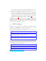
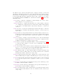
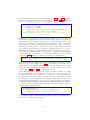
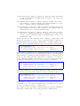
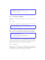
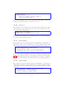
Meanwhile Figure 1.2 demonstrates the process of building and submitting a
workflow to the local gateway for execution:
2
1
2
3
4
package dispel.manual {
// Import existing and newly defined PEs.
use dispel.manual.SQLonA;
use dispel.lang.Results;
5
// Construct instances of PEs for workflow.
SQLonA sqlona = new SQLonA;
Results results = new Results;
6
7
8
9
// Specify query to feed into workflow.
String query = "SELECT * FROM AtlanticSurveys" +
" WHERE AtlanticSurveys.date before ‘2005’" +
" AND AtlanticSurveys.date after ‘2000’" +
" AND AtlanticSurveys.latitude >= 0";
10
11
12
13
14
15
// Connect PE instances to build workflow.
|- query -| => sqlona.expression;
|- "North Atlantic 2000 to 2005" -| => results.name;
sqlona.data => results.input;
16
17
18
19
20
// Submit workflow (by submitting final component).
submit results;
21
22
23
}
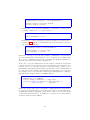
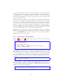
Figure 1.2: A DISPEL script which submits a workflow.
• Required components are imported from a remote source (lines 3–4) and
instantiated for use in the workflow (lines 7–8) — the new component
SQLOnA is retrieved along with a component for storing the results of any
query passed to an instance of SQLOnA.
• The workflow is constructed by connecting together all component instances (lines 17–19) and providing data for the workflow to process (lines
11–14). In this case only a single query is provided, but in reality a great
many queries may be generated from a suitable data source.
• Finally, the workflow is submitted (line 22) by providing any connected
component — by convention, the final component (results here) is the
one submitted.
This workflow, once submitted to a suitable gateway, will be validated and
deployed to any available resources. Depending on the needs of the workflow,
certain parts of the underlying workflow graph may be delegated to different
processes.
The workflow described by Figure 1.2 is rather trivial, but within Figures 1.1
and 1.2 can be found instances of all the core DISPEL constructs, to be explained
in detail in §2 and §3, allowing for more elaborate case studies to be explored
in §4.
3
1.2
Core Components
A number of components are involved in the composition and enactment of
a DISPEL workflow, each with their own distinct role. The ADMIRE project1
provides an implementation of all of these components:
Workflow A workflow is a description of a distributed data-intensive application based on a streaming-data execution model. It specifies the computational processes needed and the data dependencies that exist between
those processes. Each data element in the stream of inputs is processed by
specialised computational elements which then pass on data to the next
element; data is transferred using an interprocess communication network.
Gateway A gateway is a service-level interface exposed to the users for communication with the underlying enactment platform. This is the interface
where users submit their workflows and obtain the results from. All of
the communications with the gateway are carried out using the DISPEL
language. There may exist multiple gateways, each of which can delegate
tasks to other gateways, creating their own network.
Script A workflow is specified by a collection of statements expressed in the
DISPEL language. A DISPEL script is an ordered collection of valid DISPEL
sentences received by the gateway as a communication unit (usually stored
and submitted to the gateway as a file with the extension ‘.dispel’).
Enactment Platform After receiving a DISPEL script, the gateway first verifies that the script is valid. If the script is valid, the gateway generates
a workflow graph using concrete implementations of the abstract components in the script. These are then mapped to available (possibly distributed) resources for execution. The enactment platform is therefore
the set of resources (including hardware and software libraries) which are
available and under the control of a gateway.
To enact a workflow, a gateway might choose to employ resources directly
available only to other gateways. This can be done by delegating segments of the workflow to those other gateways, thus resulting in federated
enactment of the workflow.
Packages It is important that new components registered by DISPEL scripts
are organised in a hierarchy which reflects their functionality and use.
DISPEL supports such organisation by packaging components in such a
way that they can only be accessed within the correct context, preventing
conflicts between similarly named but otherwise distinct components.
Registry and Repository The registry is the meta-data database of the ADMIRE framework. Gateways rely on the registry during construction, interpretation, and enactment of workflows. When a DISPEL script registers
a package containing reusable definitions, the gateway validates the package by parsing the script. All of the valid definitions are then sent to the
registry for storage and cataloging. For each of the definitions, the registry
first generates the meta-data in relation to the package, and stores them
1 http://www.admire-project.eu.
4
in the reusable definitions database. The actual DISPEL sentences which
correspond to the metadata are then stored in a script repository.
Type System The DISPEL type system guarantees that all of the operations
on a set of data comply with the rules and conditions set by the language.
While processing scripts, type checks are carried out statically and dynamically to ensure that the type constraints are satisfied. If there is a
type mismatch, then correct types are inferred based on component requirements and appropriate type coercion, if feasible, is applied as and
when necessary. The type system is explored in detail in §3.
The ADMIRE workbench2 is a collection of tools for the systematic management
of DISPEL scripts and their communication with an ADMIRE gateway. It automates the construction of workflows, and the communication of data with the
gateway, thus helping less technically inclined users by concealing the underlying
programming involved in defining a workflow.
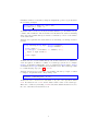
1.3
DISPEL Scripting
A DISPEL script is composed of a series of statements, each of which represents
an instruction to the ADMIRE gateway, often partitioned into statement blocks,
the execution of which is subject to certain control directives.
Statements terminate with a semi-colon (;) and will be executed in the order
in which they are given unless otherwise directed.
Connection input; Integer number = 4; ...; Boolean test = false;
Type ListConcatenate is
PE( <Connection[]:[Any] lockstep input> =>
<Connection:[Any]
output> );
ListConcatenate concat = new ListConcatenate
with input.length = number;
Aside from the ordering of statements, the layout of statements within a script
(particularly with regard to white-space) is unimportant. Blocks of statements
are specified with braces ({ and }), usually immediately succeeding some directive controlling execution within that block.
package eu.admire.manual { ... }
if (number < 3) { ... } else { ... }
PE<SQLToTupleList> lockSQLDataSource(String source) { ... }
2 http://sourceforge.net/projects/admire.
5
Statement blocks can be nested without limitation. Statement blocks are usually
attached to conditions (§5.1.1), iterators (§5.1.2) or function definitions (§3.1.5).
Aside from statements, scripts can also contain comments which will be ignored
by the DISPEL parser. Two types of comment are permitted; single-line comments and block comments which span multiple lines. Single line comments are
initiated by a double forward-slash (//) and continue until the next line-break.
Block comments are initiated by a forward-slash-asterisk (/*) and continue until
an asterisk-forward-slash (*/) is encountered.
// A single-line comment.
/* A multi-line comment -such comments can extend over many lines of text. */
Comments aside, statements are generally constructed from keywords, operators, delimiters, identifiers and literals.
• Keywords are used to identify the type of statement being made — for
example package, if or Type. The set of permissible keywords can be found
in §5.4.
• Operators are used in the construction of expressions which evaluate to
some value — for example +, / and =. The set of supported operators can
also be found in §5.4.
• Delimiters are used to delimit constructs such as tuples and lists. They
include various forms of parentheses such as (), {} and [], and separators
like , and ;. Pertinent delimiters are introduced alongside the constructs
which use them.
• Identifiers are attributed to variables, functions, new types (§3) and tuple
elements (§3.1.3). These identifiers can then be referred to by other components within the script. Valid identifiers in DISPEL must begin with an
alphabetic character, followed by any combination of alphanumeric characters and the underscore character ( ). For example Hello, hello world,
HelloWorld and hello 100 world are all valid identifiers, whilst 1Hello and
hello@world are invalid. No keyword may be used as an identifier.
• Literals inlude numbers (such as 3, 4.33, -17), character strings (for example ’A’ for single characters or "Hello world!" for longer text strings),
boolean values (true and false) and stream literals (for example |- 1,
"two", ’3’ -|. Literals are associated with types as described in §3.1, with
stream literals receiving particular attentions in §2.2.2.
Variables are declared by specifying identifiers of a given type. For example,
the following declares two variables of type Integer, and one of type Real.
Integer x, y; Real temperature;
When a variable is declared, its value can be initialised to another (already
initialised) variable, a literal, or to an expression describing an operation on
6
initialised variables or literals by using the assignment operator (=) as shown in
the following examples:
Integer day = 1, month = 6, year = 2010;
Real thrice pi = 3.1415 * 3;
A variable can be referred to in any statements within scope. A variable’s scope
consists of the remainder of the statement block in which it is declared, including
all blocks nested within that space unless over-ridden by a more local variable
of the same name.
A function is a parameterised statement block describing a recurring execution
pattern:
String substring(String input, Integer startIndex,
Integer endIndex) {
String output = "";
for (Integer i = startIndex; i < endIndex; i++) {
output += input.charAt(i);
}
return output;
}
A function is not executed immediately, but is instead invoked on demand as
often as required. A function consists of a return type (in the above example
String), an identifier (substring), a set of parameters (String input, Integer
startIndex and Integer endIndex) and a statement block. The return type must
be a valid language type (see §3.1), or void.
A function is invoked by referring to its identifier followed by a tuple of values
to assign to its parameters in corresponding order:
signature = substring(data, 17, 25);
A function can be invoked as a statement or as part of an expression unless
void. If a function is not void, then it must return a value of its return type.
This can be ensured by including a return statement within the function before
the end of the function statement block.
7
Chapter 2
Workflow Composition and
Enactment
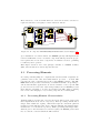
A workflow is a description of a data processing task in terms of data flowing
through interconnected processing elements which, when delegated to specific
resources in some computational platform, results in the enactment of that task.
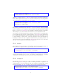
In DISPEL, a workflow is constructed from a number of processing elements
(PEs) and connections, which link PE instances together via connection interfaces defined by PE type specifications. By following the external connections
between PE instances and the internal connections within PEs, it is possible to
chart the streaming of data from source to sink; given access to the type specifications of PEs, it is then possible to propagate the structure and semantics of
data within data streams and thus verify the integrity of that data.
"uk.gov.bgs.northsea"
"bgsRules"
rules
source
data input
expression
SQLquery
Translator
and
BandPass
Filter
"SELECT ...
FROM ...
WHERE ...20050101:000000" ... AND ... "20091231:235959" ...
output
input
inputs
Merge
AllMeetsAll
Symmetric
Correlator
outputs
"eu.org.orfeus.mediterranean" "orfeusRules"
destination
rules
"eu.org.orfeus.PlateImaging"
source
SQLquery
expression
data input
output
Translator
and
BandPass
Filter
input
output
"EuropeanPlateImage05to09sample1"
Deliver
name
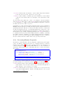
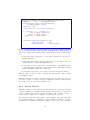
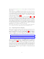
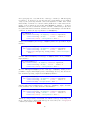
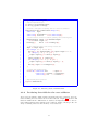
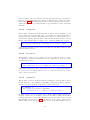
Figure 2.1: A typical DISPEL workflow.
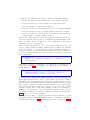
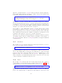
Arbitrarily complex workflows can be constructed within DISPEL by encapsulating common workflow patterns into composite PEs; this is done by instantiating these patterns within abstract PE specifications using special PE functions.
8
These functions, or the new PEs which are derived from them, can then be
registered with the local registry for later extraction and use.
TestAMA
outputs
input
List
Split
inputs
The
Comb
output
inputs
The
Comb
output
inputs
The
Comb
output
rowSplit
inputs
inputs
The
Comb
output
inputs
The
Comb
output
inputs
output output
Agg
inputs
input
List
Split
The
Comb
output
outputs
colSplit
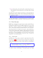
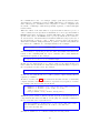
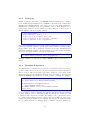
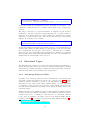
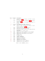
Figure 2.2: A composite PE AllMeetsAllSymmetricCorrelator, used in Figure 2.1.
Upon submission of a valid workflow, the ADMIRE gateway will implement all
referenced PEs with concrete executable components which possess the properties required and execute these components on available resources, optimising
for efficiency where possible.
This chapter describes each of the principle elements of a DISPEL workflow
(PEs, data streams and connections) and their use.
2.1
Processing Elements
Processing elements (PEs) are computational activities which encapsulate algorithms, services and other data transformation processes — as such, PEs
represent the basic computational blocks of any DISPEL workflow. The ADMIRE framework provides a rich library of fundamental PEs corresponding to
various data-intensive applications, as well as a number of more specific PEs
produced for selected use-cases. Just as importantly however, DISPEL provides
users with the capability to produce and register new PEs, either by writing
new ones in other languages, or by creating compositions of existing PEs.
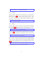
2.1.1
Processing Element Characteristics
Available PEs are described in a registry associated with a given gateway and
their implementations stored in a repository. Each processing element has a
unique name within the registry. This name helps the enactment platform
identify a specific PE, and is also used to link the PE with any available implementations to be found in the repository. While generating this unique name,
which is part of the metadata stored in the registry, the DISPEL parser takes
into account the context in which the PE is defined.
9
In addition to the PE name, the registry contains for each PE specification:
• A brief description of its intended function as a workflow component.
• A precise description of expected input and output data streams.
• A precise description of its iterative behaviour.
• A precise description of any termination and error reporting mechanisms.
• A precise description of type propagation rules from inputs to outputs.
• A precise description of any special properties which could help the enactment engine to optimise workflow execution.
Some of these characteristics are fixed upon registration with the registry (e.g.
expected behaviour), whereas some are configurable upon instantiating an instance of a PE for use in a workflow (e.g. some optimisation properties and
certain aspects of type propagation).
Almost all PEs take input from one or more data streams and produce one
or more output streams accordingly. Different types of PE provide different
connection interfaces — by describing the connection interfaces available to a
given type of PE, we provide an abstract specification for that type which can
be used to construct new PEs. The internal connection signature of a PE takes
the following form:
PE( [Declarations ]
<Input_1 , ..., Input_m > => <Output_1 , ..., Output_n > )
[with Properties ]
Each input / output is a declaration of a Connection or a declaration of a
Connection array (§2.1.4). For example, the following is the type signature of
the PE SQLQuery:
PE( <Connection:String::"db:SQLQuery" terminator expression;
Connection:String::"db:URI"
locator
source> =>
<Connection:[<rest>]::"db:TupleRowSet" data> )
From this it can be inferred that SQLQuery has three connection interfaces; two
input (expression and source), and one output (data). It can also be inferred
that expression accepts database queries represented by strings, source accepts
universal resource identifiers likewise represented by strings, and data produces
lists of tuples of undisclosed format as results. Finally, it can be inferred that
source provides information which can be used to locate a data source (which
can then be taken into account when assigning execution of an instance of
SQLQuery to a specific service or process) and that when the stream connected
to expression terminates, the instance of SQLQuery can itself be terminated (see
§2.1.5 for more on connection modifiers).
In addition, it is possible to extend the internal connection signature of a PE
with additional type declarations and PE properties — examination of such type
declarations is deferred to §3.1.4, whilst PE properties are discussed in §2.1.6.
10
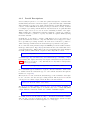
2.1.2
Processing Element Instances
Before a PE can be used as a workflow component, an instance of that PE
must first be created. A PE can be instantiated many times, and each of these
instances is referred to as a Processing Element Instance, or PEI.
A PEI is the concrete object used by the enactment engine while assigning
resources. It is created from a PE using the new keyword, as follows:
SQLQuery sqlq = new SQLQuery;
In this case, SQLQuery is a PE and sqlq is its PEI.
While creating PEIs, a programmer can re-specify any PE properties which are
still modifiable. This is achieved using the with directive. For example, during
the following instantiation of SQLQuery the programmer explicitly specifies more
concretely the data-stream format for the communication interface data, which
is the output interface specified for all instances of SQLQuery:
SQLQuery sqlq = new SQLQuery
with data as :[<Integer i, j; Real r; String s>];
The assertion, with data as :[<Integer i, j; Real r; String s>], only applies
to the connection interface named data of the PEI named sqlq. This assertion
does not affect the original definition of the SQLQuery PE.
It is permissible to use with to:
• Refine the structural type of a connection interface or array of connection
interfaces to a subtype of the original type (see §3.2.7):
Combiner combine = new Combiner with inputs as :[Integer];
• Refine the domain type of a connection interface or array of connection
interfaces to a subtype of the original type (see §3.3.3):
Combiner combine = new Combiner
with inputs as ::"manual:DistrictPopulation";
• Impose modifiers on connections or connection arrays for control or optimisation purposes (see §2.1.5):
Combiner combine = new Combiner with permutable inputs;
• Specify PE properties, such as the size of a connection array, upon instantiation (see §2.1.6):
Combiner combine = new Combiner with inputs.length = 3;
• Rename a connection interface:
11
Combiner combine = new Combiner with output as merged;
It is also permissible to combine modifiers arbitrarily. For example:
Combiner combine = new Combiner
with permutable inputs as :[Integer]::"manual:DistrictPopulation",
inputs.length = 3,
output as merged::"manual:NationalPopulation";
Using with allows PE instances be significantly modified for particular scenarios;
for recurring scenarios however, it will often be better to define a new PE type
with the properties desired.
2.1.3
Defining New Types of Processing Element
It is possible to define new types of PE by modifying existing types. For example:
Type SymmetricCombiner is Combiner with permutable inputs;
This use of with obeys the same rules as described previously, but applies to all
instances of the new PE type rather than just to a single instance. It is also
possible to define entirely new types of PE by describing its internal connection
signature. For example:
Type SQLToTupleList is
PE( <Connection:String::"db:SQLQuery" expression> =>
<Connection:[<rest>]::"db:TupleRowSet" data> );
Such PEs are referred to as abstract PEs because, by default, there exists no
implementation for these PEs which can be used by the enactment platform
to implement workflows which use them. In such a scenario, abstract PEs
cannot be instantiated. Therefore it becomes necessary to make these PEs
implementable by use of special PE functions. The following function describes
how to implement an instance of SQLToTupleList:
PE<SQLToTupleList> lockSQLDataSource(String dataSource) {
SQLQuery sqlq = new SQLQuery;
|-repeat enough of dataSource-| => sqlq.source;
return PE( <Connection expression = sqlq.expression> =>
<Connection data
= sqlq.data> );
}
PE functions return descriptions of how a PE with a given internal connection
signature can be implemented using existing PEs. The notation PE<Element >
designates the type of all subtypes of PE Element (see §3.1.6), which is shorthand
for its internal connection interface — without this notation, the above function
would return an instance of SQLToTupleList, rather than an implementable subtype.
12
Using a PE function, an implementable variant of a given abstract PE can be
defined which can then be instantiated freely:
PE<SQLToTupleList> SQLOnA = lockSQLDataSource("uk.org.UoE.dbA");
SQLOnA sqlona = new SQLOnA;
Implementable PEs which are not primitive PEs (i.e. PEs described by function templates rather than PEs with prior implementations drawn from a local
repository) are often referred to as composite PEs, since they are commonly
defined using compositions of other implementable PEs, primitive or otherwise.
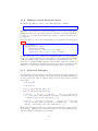
2.1.4
Connection Interfaces
A connection interface is described by an annotated declaration of language
type Connection (§3.1):
Connection[:StructuralType][::DomainType] [modifier]* identifier
A basic connection interface requires only an identifier; an interface can also
be annotated however with the expected structure and domain type of any
data streamed through it (§3.2 and §3.3 respectively) and with any number of
connection modifiers (§2.1.5) as appropriate.
Connection interfaces are defined within PE type declarations:
Type AbstractQuery is
PE( <Connection:String::"db:SQLQuery" expression> =>
<Connection:Any::"db:Result" data> );
Connection interfaces can be assigned other Connection types as part of the
return value of PE constructor functions:
PE<AbstractQuery> makeImplementableQuery( ... ) {
Connection input;
Connection output;
... // Body of function . . .
return PE( <Connection expression = input> =>
<Connection data
= output> );
}
Connection interfaces within a PE are defined as being input interfaces or output interfaces based on the internal connection used within that PE. Certain
connection modifiers are only applicable to input interfaces or only applicable
to output interfaces — to apply a connection modifier to an interface of the
wrong kind is an error.
Connection interfaces can be further defined for particular subtypes of PE, or
for particular instantiations of PEs:
Type ListVisualiser is Visualiser with locator input as :[Any];
13
ListVisualiser visualiser = new ListVisualiser
with input as :[Integer]::"manual:PopulationList";
Such refinements can only be used to create a valid subtype of the original
Connection declaration. Connection interfaces can also be defined in arrays:
Connection[][:StructuralType][::DomainType] [modifier]* identifier
Any structural or domain type information is assumed to apply to each individual interface in the array. Connection modifiers may have different meanings
however when applied to arrays than when applied to individual interfaces (see
§2.1.5):
Type TupleBuild is
PE( <Connection:[String] keys; Connection[] lockstep inputs> =>
<Connection:<rest> tuple> );
The size of a connection array should be defined upon creating an instance of
any PE with such an array:
TupleBuild build = new TupleBuild with inputs.length = 4;
Finally, because internal connection signatures are defined by connecting two
tuples of connection interfaces (see §3.1.3), it is possible to group connection
interfaces with similar specifications together as so:
Type DocumentBuilder is
PE( <Connection:String::"manual:text"
successive header, body, footer> =>
<Connection:String::"manual:document" document> );
Structural and domain type annotations apply to all such groupings of interfaces;
connection modifiers apply to all grouped interfaces as if applied to an array of
interfaces.
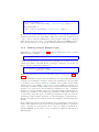
2.1.5
Connection Modifiers
Connection modifiers are used to indicate particular aspects of a PE or PEI’s
internal connection signature which either:
• Affect how the a PEI interacts with other components in a workflow.
• Provide information to the enactment platform as to how to best implement a workflow containing such a PEI.
• Provide information to the developers wishing to produce new implementations for existing PEs.
14
They are applied either to the declaration of a connection interface within an
abstract PE definition, or to the re-definition of an interface during the instantiation or subtyping of an existing PE. For example:
Type SQLQuery is
PE( <Connection:String::"db:SQLQuery" terminator expression;
Connection:String::"db:URI"
locator
source> =>
<Connection:[<rest>]::"db:TupleRowSet" data> );
Type LockedSQLQuery is SQLQuery
with initiator source, requiresStype data;
LockedSQLQuery query = new LockedSQLQuery
with preserved("localhost") data
as :[<Integer key; String result>];
The input interfaces expression and source of PE type SQLQuery are modified with terminator and locator respectively. A sub-type of SQLQuery called
LockedSQLQuery is then defined which assigns an additional modifier initiator
to source as well as requiresStype to output interface data. Finally, a specific instance of LockedSQLQuery is created wherein data is further modified with
preserved; the structural type of data is also refined as required by the earlier
modification of data with requiresStype. Thus, the internal connection signature of query is:
PE( <Connection:String::"db:SQLQuery" terminator
expression;
Connection:String::"db:URI"
locator initiator source> =>
<Connection:[<Integer key; String result>]::"db:TupleRowSet"
requiresStype preserved("localhost") data> );
Connection modifiers are applied either during the declaration of a Connection
interface or Connection array as defined in §2.1.4, or during the refinement or
instantiation of a PE using with as demonstrated above. Multiple modifiers can
be applied at once by declaring them successively:
Type EncryptedQuery is SQLQuery
with encrypted preserved("localhost/secured") data;
Some modifiers take parameters. These parameters are listed in parentheses
immediately after the modifier keyword:
Type AbstractLearner is
PE( <Connection model; Connection training;
Connection after(model, training) test> =>
<Connection results> );
Most connection modifiers are applicable both to input and output connection
interfaces; however a few are only applicable to inputs or outputs exclusively (or
have different meanings when applied to an input or output as with encrypted).
15
In addition, most connection modifiers can be applied to arrays of connections
as well as to individual connections — there also exist however a subset of modifiers which are only applicable to arrays (generally concerning the relationship
between individual interfaces within the array). The complete set of connection modifiers available in DISPEL are described in detail in §5.2, but are also
summarised here:
after is used to delay the consumption of data through one or more connec-
tions. [Requires a list of predecessors.]
compressed is used to compress data streamed out of the modified connection
or to identify the compression used on data being consumed when applied
to an output or an input interface respectively. [Requires a compression
scheme.]
default is used to specify the default input streamed through a connection
should input be otherwise left unspecified. [Requires a stream expression;
input only.]
encrypted is used to encrypt data streamed out of the modified connection or to
identify the encryption scheme used on data being consumed when applied
to an output or an input interface respectively. [Requires an encryption
scheme.]
initiator is used to identify connections which provide only an initial input
before terminating. Inputs maked initiator are read to completion before
reading from inputs not so marked. [Input only.]
limit is used to specify the maximum number of data elements (see §2.2.2)
a connection will consume or produce before terminating. [Requires a
positive integer value.]
locator is used where the modified connection indicates the location of a re-
source to be accessed by the associated PEI (which might influence the
distribution of the workflow upon execution). [Input only.]
lockstep indicates that one data element must be streamed through every
interface in the modified array before another element can be streamed
through any of them. [Connection arrays only.]
permutable indicates that a given array of inputs can be read from in any order
without influencing the outputs of the PEI. [Input connection arrays only.]
preserved indicates that data streamed through the modified connection should
be recorded in a given location. [Requires a URI, or goes to a default
location.]
requiresDtype dictates that upon instantiation, the specific domain type of the
modified connection must be defined.
requiresStype dictates that upon instantiation, the specific structural type of
the modified connection must be defined.
roundrobin indicates that a data element must be streamed through each in-
terface in the modified array in order, one element at a time. [Connection
arrays only.]
16
successive indicates that each interface of the modified array must terminate
before the next one is read. [Connection arrays only.]
terminator causes a PEI to terminate upon the termination of the modified
connection alone (rather than once all inputs or all outputs have terminated).
Not all connection modifiers can co-exist — for example a connection interface
denoted initator cannot also be denoted after unless it is after another initiator. If an instance of a PE is created with mutually incompatible connection
modifiers, then an error will be reported.
One further note. The enactment platform which actually executes a submitted
DISPEL workflow may have at its disposal many alternate implementations of a
given PE specification. The use of connection modifiers can serve to restrict and
modify (via wrappers) the use of certain implementations. It may also be the
case however that some implementations tacitly impose certain connection modifiers themselves (for example, assuming all inputs are in lockstep) that may not
be explicitly referenced by the abstract PE specification, resulting occasionally
in workflow elements consuming or producing data in an unexpected manner.
In essence, the more precisely a PE is defined in DISPEL, the more confidence
the user can have that the workflow will execute precisely as intended.
2.1.6
Processing Element Properties
In addition to a PE’s internal connection signature, additional properties applicable to the PE type definition as a whole or to arbitrary subsets of connection
interfaces can be defined.1 These can be appended either to the declaration of a
connection interface within an abstract PE definition, or to the re-definition of
an interface during instantiation or subtyping, just as for connection modifiers.
For example:
Type DataProjector is
PE( <Connection:String::"dispel:URI"
source;
Connection[]:[Integer]::"data:Vector" vectors> =>
<Connection:[<rest>]::"data:Projection" projection>
with lockstep(source, vectors) );
SQLQuery query = new SQLQuery with lockstep(source, expression);
PE properties are attached using the with directive as described in §2.1.2. The
properties available are described in detail in §5.3, but are summarised below:
lockstep indicates that a data element must be streamed through every pro-
vided interface before another element can be streamed through any of
them. [Requires a list of interfaces to modify.]
permutable indicates that a given subset of inputs can be read from in any
order without influencing the outputs of the PEI. [Requires a list of input
interfaces to modify.]
1 Not
currently implemented.
17
roundrobin indicates that a data element must be streamed through each of a
subset of interfaces in the order provided, one element at a time. [Requires
a list of interfaces to modify; the list must consist solely of inputs or solely
of outputs.]
Note that some properties replicate the behaviour of connection modifiers for
arbitrary subsets of the set of a PE’s connection interfaces. In addition there exists a special property length for all connection arrays which is typically defined
upon instantiation of a PE:
DataProjector project = new DataProjector with vectors.length = 5;
The effect of this is simply to concretely define the size of a connection array.
Currently this is not required, but should be considered the preferred convention.
2.2
Data Streams
DISPEL uses a streaming-data execution model to describe data-intensive activities. All of the PEIs in a workflow application interact with one another
by passing data. Data produced by one PEI is consumed by one or more other
PEIs. Hence, to make the communication between PEIs possible, DISPEL allows
users to define external connections between PEIs. These connections channel
data between interdependent PEIs as streams via their connection interfaces.
Every data stream can be deconstructed as a sequence of data elements with a
common abstract structure, which can then be validated against the structure of
data expected by a given interface. PEIs will consume and produce data element
by element according to the specification of its immediate PE type, defined upon
instantiation of the PEI. In DISPEL however, the specifics of data production
and consumption are generally hidden, delegating the tasks of buffering and
optimisation to the enactment platform.
2.2.1
Connections
In DISPEL, there exist two types of connection; internal and external. Internal connections are defined in the specification of PEs, and have already been
encountered in §2.1.1 and elaborated upon in succeeding sections. An internal
connection links any number of input connection interfaces to any number of
output connection interfaces, but only one such connection can exist within a
given PE:
PE( <Connection:String::"db:SQLQuery" terminator expression;
Connection:String::"db:URI"
locator
source> =>
<Connection:[<rest>]::"db:TupleRowSet" data> )
An external connection is established by linking an output connection interface
of one PEI to an input of another PEI (or occasionally, an input of the original
18
PEI should some form of iterative activity be desired). Assume the existence of
two PEs, Producer and Consumer with the following PE type definitions:
Type Producer is
PE( <> => <Connection output; Connection[] outputArray> );
Type Consumer is
PE( <Connection input; Connection[] inputArray> => <> );
Now assume two PEIs, designated producer and consumer:
Producer producer = new Producer with outputArray.length = 3;
Consumer consumer = new Consumer with inputArray.length = 3;
To refer to the communication interfaces of a given PEI, we use the dot operator
(.). On the left-hand side of this operator must be a reference to a PEI, and on
the right-hand side must be a reference to an interface. For example, we refer to
the input interface of the consumer PEI as consumer.input; similarly, the output
interface of producer as producer.output. A connection can be established using
the connection operator (=>), as shown below:
producer.output => consumer.input;
Any given output connection interface can be connected to multiple input connection interfaces; all data transported is replicated across all connections. It is
not permissible to connection multiple output connection interfaces to a single
input interface however — if a merger of outputs is desired, then a suitable
PE must be provided to act as intermediary in order to resolve precisely how
multiple outputs should be merged. All interfaces of a PEI must be connected
to something else witin a workflow.
There exist four special interfaces to which other interfaces may be connected
— these are discard, warning, error and terminate. Each of these interfaces
may only be used as the target of a connection, and each of them send data to
a predetermined location:
• Data sent to discard is discarded and lost — this is useful in case where
the user cares only for a subset of a PEI’s outputs:
DivisionFilter filter = new DivisionFilter;
...
filter.divisible => collector.input;
filter.remainder => discard;
If an output of a PE instance is left unconnected, then it is assumed to
be connected to a discard interface.
• Data sent to warning is generally sent to be recorded and reported to
the user — this is useful if a PEI has an output specifically for reporting
problems with execution:
19
DocumentValidator validator = new DocumentValidator;
...
validator.output => processor.document;
validator.invalid => warning;
• Data sent to error is treated similiarly to data sent to warning, but is
generally considered to be of greater import:
SafeDivisionFilter filter = new SafeDivisionFilter;
...
filter.divideByZero => error;
• Data sent to terminate is discarded and lost as with discard, but a NmD token (see §2.2.2) will also be immediately sent back through the connection
upon receiving any data:
DivisionFilter filter = new DivisionFilter;
...
filter.divisible => collector.input;
filter.remainder => terminate;
Data sent to warning or error should generally be small in size, only describing
the event which triggered the warning or error — it should not be assumed that
the location to which such data is sent can handle the significant quantities of
data associated with data-intensive applications.
In the case of composite PEs defined by PE constructor functions, the internal
connection defined by the internal connection signature of the PE will be implemented by a set of internal ‘external’ connections linking together a set of
internal PEs, which themselves may have their internal connections implemented
by connections between further internal PEs if they themselves are composite.
For example, take a composite PE of abstract type SQLToTupleList constructed
using the simple wrapper function lockSQLDataSource:
PE<SQLToTupleList> lockSQLDataSource(String dataSource) {
SQLQuery sqlq = new SQLQuery;
|-repeat enough of dataSource-| => sqlq.source;
return PE( <Connection expression = sqlq.expression> =>
<Connection data
= sqlq.data> );
}
In this case, the internal connection signature of SQLToTupleList is implemented
by connecting input expression to the expression input of an internal instance
of SQLQuery (a primitive PE) whilst output data is connected to the data output
of that same internal instance. A slightly more complex case is demonstrated
by function makeCorroboratedQuery:
20
PE<CorroboratedQuery> makeCorroboratedQuery(Integer sources) {
SQLQuery[]
sqlq
= new SQLQuery[sources];
ListConcatenate concat = new ListConcatenate
with input.length = sources;
Connection
expr;
Connection[] srcs = new Connection[sources];
for (Integer i
expr
srcs[i]
sqlq[i].data
}
= 0; i < sources; i++) {
=> sqlq[i].expression;
=> sqlq[i].source;
=> concat.input[i];
return PE( <Connection expression = expr;
Connection sources
= srcs;
<Connection data
= concat.output> );
}
In this case, the internal connection signature of CorroboratedQuery (assumed
here to be much the same as the signature of SQLQuery albeit with an array of
data source inputs sources rather than a single input source) is implemented
by:
• Connecting input expression to every input expression of an array of
SQLQuery instances.
• Connecting each input in interface array sources to the input source of a
different instance of that same SQLQuery array.
• Connecting each output expression of every instance of the SQLQuery array
to a different input of an instance of ListConcatenate, a PE which combines
lists from multiple inputs into a single list.
• Connecting output data to the output of the ListConcatenate instance.
This produces a composite PE for querying databases which collates results
from multiple sources.
Thus all workflows, even when constructed using composite PEs, can be decomposed into a graph of connections between primitive ‘black-box’ PEs showing
the complete flow of data from beginning to end.
2.2.2
Stream Literals
Typically, a PEI processes data-stream elements that it receives via its input
connection interfaces, consuming input through each interface one element at
a time. A single data element could be an integer value, a string, a tuple of
related values, a single row of a matrix or something else entirely.
The enactment platform is responsible for the buffering of the data units that
are flowing through the communication objects within a workflow. It is also
responsible for optimising the mapping of PEIs to resources in order to minimise
21
the communication costs — for example, opting to pass data by reference when
data units are communicated between PEIs which have been assigned to the
same address space; serialisation and compression of data for long-haul data
movement; or buffering to disk when specifically requested, or when buffer spill
is unavoidable.
When the values of the data units for a given stream are known a priori, or
can be evaluated as an expression at instantiation, it can be specified within a
DISPEL script itself. Consider for example PEs which only communicate with
specific data sources. In DISPEL, these a priori specifications are referred to
as stream literals. Stream literals are identified within the script by the use of
the stream literal operators |- and -|. These operators enclose an expression,
which when evaluated during instantiation, generate a stream entity which can
be connected to a PEI via one of its input interfaces. For example
|- "Hello", "World" -| => consumer.input;
If it is necessary to repeatedly produce the same data within a stream for the
benefit of the consuming PEI, the repeat construct can be used within the
stream literal expression. For example:
|- repeat 10 of "Hello" -| => consumer.input;
In this case, the string literal "Hello" will be passed to the input interface ten
times. When it is uncertain how many times a given literal must be repeated,
the enough keyword can be used. For example:
|- repeat enough of "Hello" -| => consumer.input;
In this case, the string literal "Hello" will be passed to input as many times as
required by consumer.
As will be described in §3.2, data elements in streams can take on arbitrarily
complex structure; internally streams are represented by sequences of tokens.
For example, take the following stream literal:
|- [<number = 1; decimal = {0.1, -3.4, 5.23, 4.0}; text = "text">,
<number = 2; decimal = {5.36, 5.365, 3.0, 9.9};
text = "more text">] -|
:[<Integer number; Real[] decimal; String text>]
Whilst the precise format of data in a stream depends on the implementation of
components in the enacted workflow, for the purposes of stream construction,
the above stream can be represented as so:
SoS SoL SoT number 1 decimal SoA 0.1 -3.4 5.23 4.0 EoA text "text"
EoT SoT number 2 decimal SoA 5.36 5.365 3.0 9.9 EoA text
"more text" EoT EoL EoS
Streams are assumed to be constructed using the following tokens:
22
• SoS / EoS indicates the start / end of a stream.
• SoA / EoA indicates the start / end of an array.
• SoL / EoL indicates the start / end of a list.
• SoT / EoT indicates the start / end of a tuple.
• Constants of primitive types (Boolean, Integer, String, etc.) are inserted
into the stream as-is.
• Labelled types within tuples (e.g. number, decimal and text in the example above) are transmitted in two parts: the label itself, followed by the
assigned data. Note that for complex data, tokens indicating the start
and end of array / list / tuple types will indicate the scope of the data
following the initial label. Note also that tuple elements therefore cannot
be labelled with any of the above tokens (e.g. it is not permissible to label
an element ‘SoL’).
Any implementation is at liberty to use another internal representation if desired, provided that it supports the semantics described above.
In addition, there exists a special token, NmD (No more Data), which can be
sent upstream by a PEI in order to request no further transmission of data
— this is most relevant for connections which transmit data continuously until
requested not to by PEIs further along a workflow. There is no need however
to explicitly provide a backwards connection between PEIs in order to transmit
such a token, nor is there any need to explicitly reference the NmD token; fine
control of stream data is always handled automatically by PEIs in accordance
with the specification of their source PEs. Similarly, there is no reason to
explicitly reference SoS or EoS. It is possible to reference other structural tokens
however when constructing streams:
Stream partial = SoL;
for (Integer i = 0; i < array.length(); i++) {
partial = partial + array[i];
}
Stream complete = partial + EoL;
The structural type of stream literals is inferred from their construction. Partially constructed stream literals (stream literals for which every instance of a
structural token is not matched by its complement like partial above) cannot
be connected to a connection interface without raising an error. It should be
noted that in most cases, users are better served by making use of built-in stream
functions to construct stream literals, rather than attempting to construct them
manually using stream tokens.
2.3
Registration and Enactment
The registry is the knowledge base of the entire ADMIRE framework. This is
where all of the information concerning components, types and functions are
stored. For an application to be executable within the ADMIRE framework, all
23
of the relevant information must be first made available to the registry. This is
because, when a gateway receives a workflow specification submitted in the form
of a DISPEL script, it communicates with the registry to resolve dependencies
and identify implementations of logical components before the workflow is sent
to the enactment platform.
When a dispel script is submitted for enactment, the underlying workflow graph
described by the script is built using definitions provided by the registry and
then used to select suitable implementations of components from an available
code repository. Execution of those components is then delegated to various
available resources; the enactment platform will attempt to optimise this process by accounting for the location and inter-connectivity of resources, drawing
upon any additional information provided by the dispel script in the form of
connection modifiers (like locator) and general PE properties.
DISPEL provides constructs for two-way communication between the DISPEL
parser in the gateway and the registry service interfaces. These are register
for exporting ADMIRE entities to the registry and use for importing already
registered entities from the registry.
2.3.1
Exporting to the Registry
Example 1.1 in Chapter 1 illustrated the register directive, the critical parts
of which are reproduced below:
package dispel.manual {
...
Type SQLToTupleList is PE( ... );
PE<SQLToTupleList> lockSQLDataSource(String dataSource) { ... };
register lockSQLDataSource;
}
In the DISPEL code segment above, a function is specified which produces a PE
which directs queries to a specific data source; this function can now be used
to generate a multitude of application domain-specific processing elements with
their own respective data sources. Since it is prudent to save recurring patterns
for reuse, this function can be registered with the registry using the register
construct:
register Entity_1, Entity_2, ...;
It is also possible to register elements with additional annotations. These additional annotations will be recorded by the ADMIRE registry, and can be used
to provide valuable additional information to possible users. This is done by
adding with to the register statement:
register SQLToTupleList, lockSQLDataSource
with @author = "Anonymous", @description = "...";
24
Annotations take the form @annotation and are assigned text strings describing
their content.
During registration, the DISPEL parser automatically collects all of the dependencies, and stores this information with the entity being registered. In doing
so, the registry guarantees that any new registration is self-contained and is
reproducible when exported from the registry. Of course, this guarantee is limited by the scope in which the entity is defined — in particular its containing
package (discussed in detail in §2.3.3).
Consider the function lockSQLDataSource as defined in Figure 1.1 on page 2.
It depends on SQLQuery, an existing PE. When registering lockSQLDataSource,
the registry will only make a note that lockSQLDataSource depends on SQLQuery.
However, if there is a dependency where the required entities are not already
in the registry, the DISPEL parser will automatically register all of the entities
defined within the same package before registering the entity. For example, in
the script segment in the previous section, the definition of SQLToTupleList will
be registered automatically before lockSQLDataSource is registered, even though
SQLToTupleList is not explicitly registered by the script.
If the required dependencies do not exist locally, and the required entities have
not been imported from the registry, then the parser will raise an error.
2.3.2
Importing from the Registry
Entities imported from the registry associated with a given gateway are needed
for evaluation of DISPEL scripts. Imports are made using the use directive. To
illustrate this construct, reconsider the example in Figure 1.1. In this example,
function lockSQLDataSource depends on the PE, SQLQuery. To import SQLQuery
so that it is available to the gateway during the construction of the workflow
defined by lockSQLDataSource, the use construct must be applied as shown here:
use dispel.db.SQLQuery;
use dispel.core.{ListSplit, ListMerge};
Each use statement must identify one or mre DISPEL entities to be imported,
prefixed by a qualified package name, a mechanism used by the platform for
name resolution (see §2.3.3). To import multiple entities from different packages, a DISPEL script can have multiple use statements. In the above examples, the first statement imports the entity named SQLQuery from the dispel.db
package whereas the second statement imports ListSplit and ListMerge from
the dispel.core package. Every entity that is used by a script must either be
defined in the same package as the dependent entity, be imported from the registry before they can be used to compose a workflow, or be defined in the special
dispel.lang package.
25
2.3.3
Packaging
During registration and usage, the ADMIRE framework must protect declarations, definitions and instantiations of DISPEL components from conflicts with
unrelated but similarly-named components. To avoid component interference,
DISPEL uses a packaging methodology similar to that of Java. Registration of
related components are grouped inside a package using the package keyword.
This is illustrated in the following example:
package dispel.manual {
Stype Cartesian is <Real x, y, z>;
Stype Polar is <Real radius, theta, phi>;
Stype Geographical is <Real latitude, longitude>;
register Cartesian, Polar, Geographical;
}
Here, three structural types are being registered that may be used for representing geographical positions. As they are defined within a package named
dispel.manual, they will be managed separately from other similarly-named
definitions within the registry. If a user wishes to use any of these structural
types, the user must include a relevant use statement:
use dispel.manual.{Cartesian, Polar, Geographical};
Multiple packages are allowed in a single DISPEL script, but should not be
nested.
2.3.4
Workflow Submission
A workflow must be submitted for execution over available resources in order to
produce results. Every resource is controlled by an gateway. The gateway hides
these resources, instead providing appropriate interfaces for accessing them.
These interfaces are in turn hidden from the user, and must be invoked from
within the DISPEL script. This is done using a submit command. For example:
use dispel.manual.sieve.PrimeGenerator;
use dispel.manual.sieve.makeSieveOfEratosthenes;
PE<PrimeGenerator> SieveOfEratosthenes
= makeSieveOfEratosthenes(100);
SieveOfEratosthenes sieve = new SieveOfEratosthenes;
submit sieve;
Upon receiving a submit command, the gateway will check that the workflow
is valid. This is done by expanding workflow patterns (as described by PE
constructor functions) and by checking the validity of the connections between
processing element instances for type safety. Once the workflow is deemed executable, the gateway initialises the computational activities encapsulated within
the processing elements by assigning them to available resources. Finally, the
26
connections between these computational activities are established in accordance with the workflow by allocating transport channels to connection objects.
The submit command has the following syntax:
submit instance_1, instance_2, ...;
A workflow could either comprise a single PEI, or a collection of PEIs abstracted
using a higher-level specification, e.g. functions. Nonetheless submission of entire workflows is performed by submitting any part of the workflow. For example:
PE<PrimeGenerator> SoE100 = makeSieveOfEratosthenes(100);
SoE100 sieve100 = new SoE100;
submit sieve100;
...
PE<PrimeGenerator> SoE512 = makeSieveOfEratosthenes(512);
PE<PrimeGenerator> SoE1024 = makeSieveOfEratosthenes(1024);
SoE512 sieve512 = new SoE512;
SoE1024 sieve1024 = new SoE1024;
submit sieve512, sieve1024;
It is possible to submit multiple disjointed workflow compositions simultaneously using a single submit command. This is shown in the above example,
where soe512 and soe1024 are submitted using a single submit command. Finally, there can be multiple submit commands within a single DISPEL script.
2.3.5
Processing Element Termination
In a distributed stream processing platform, termination of computational activities must be handled appropriately to avoid resource wastage. If unused
PEIs are not terminated, then they will continue to claim resources allocated
to them whilst the PEI was active. In the platform, a PEI is terminated when
either all the inputs from its sources are exhausted, or all the receivers of its
output have indicated that they do not want any more data:
• The first case occurs when all of the input interfaces of the PEI have
received an EoS token (end-of-stream; see §2.2.2), or an input interface
designated terminator (see §2.1.5) has received an EoS token. In this case,
the PEI will finish processing pending data elements and, when done,
will send any final results through its output interfaces. The PEI will
then send an EoS token to all of its output interfaces and a NmD (no-moredata) token through any still-active input interfaces. This will trigger a
cascading termination effect in all PEIs which depend on the terminated
PEI.
• The second case occurs when a PEI receives a NmD token back through
all of its output interfaces, or when it receives a NmD token back through
any output interface designated terminator, signifying that no more data
is required. In this case, the PEI will convey the message further up the
workflow by relaying a NmD token back through all of its input interfaces
27
and an EoS token through any still-active output interfaces. This will
likewise create a cascading termination effect.
Cascading termination through the propagation of termination triggers helps
the platform reclaim resources for enactment of other DISPEL scripts.
28
Chapter 3
The DISPEL Type System
DISPEL introduces a sophisticated type system for validation and optimisation of workflows. Using this type system, gateways are not only capable of
checking the validity of a DISPEL sentence (e.g. for incorrect syntax), but also
validate the connection between processing elements (e.g. for incorrect connections where the type of output data produced by a source processing element
does not match the type of input data expected by a destination processing element). Furthermore, this type system exposes the lower-level structure of the
streaming-data being communicated through valid connections so that workflow optimisation algorithms implemented beyond the ADMIRE gateways can
re-factor and reorganise processing elements and their various inter-connections
in order to improve performance.
The DISPEL language uses three type systems to validate the abstraction, compilation and enactment of DISPEL scripts — language, structural and domain.
• The language type system statically validates at compile-time if the operations in a DISPEL sentence are properly typed. For instance, the language
type checker will check if the control variables in a loop iterator or indices
of an array are of the correct type, and that the parameters supplied to a
function invocation match the type of the formal parameters specified in
the function’s definition.
• The structural type system describes the format and low-level (automated)
interpretation of values that are being transmitted along a connection between two processing element instances. For example, the structural type
system will check if the data flowing through a connection is a sequence
of tuples as expected or a sequence of integers instead.
• The domain type system describes how application-domain experts interpret the data which is being transmitted along a connection in relation
to the application at hand. For instance, the domain type system will
describe if the data flowing through a connection is a sequence of aerial or
satellite image stripes, each stripe being represented as a list of images.
Figure 3.1 illustrates some of DISPEL’s type constructs. Language types, structural types, and domain types are defined respectively using Type (line 10,
29
1
2
3
package dispel.manual {
// Define domain namespace.
namespace manual "http://www.dispel-lang.org/resource/manual";
4
// Define custom structural and domain type aliases.
Stype InitType is <Integer firstValue, step>;
Dtype Taggable represents "manual:CountableObject";
5
6
7
8
// Define a new PE type.
Type TagWithCounter is
PE( // Define input connection interfaces ‘init’ and ‘data’.
<Connection:InitType::"manual:Iteration_Control"
initiator init;
Connection:Any::Taggable data> =>
// Define output interface ’output’.
<Connection:<Integer::"manual:OrderedSequence" tag;
Any::Taggable value>
::"manual:PreserveOrder" output> );
9
10
11
12
13
14
15
16
17
18
19
// Register the new entity.
register TagWithCounter;
20
21
22
}
Figure 3.1: An example of the DISPEL type system in use.
§3.1.6), Stype (line 6, §3.2.6), and Dtype (line 7, §3.3.2) statements. Since domain types are associated with ontological definitions, we use the namespace
keyword (line 3, §3.3.1) to refer to existing ontology locations.
Structural and domain types, once defined, can then be attributed to connection
interfaces. Structural types are attached to Connection declarations using the
‘:’ connector whilts domain types are attached (usually immediately after a
structural type) using the ‘::’ connector. Literal references to domain types
are always enclosed inside double quotes (see lines 12 to 18). Complex structural
types may permit domain typing of constituent elements (see lines 16 and 17).
Specification of structural and domain types is optional, but provides valuable
information to the ADMIRE gateway when implementing a workflow as well as
assisting the user in verifying the correctness of code.
3.1
Language Types
The language type system only applies to the evaluation of DISPEL sentences
to assist during the validation of the correctness of those sentences. It is a
statically checkable type system where type checking is based on the structural
equivalence of the types, as opposed to name equivalence (as used in Ada, for
example).
The language type system initially consists of predefined base types, which are
then extended using well-formed type constructors that can be applied recur-
30
sively to the base types, or user-defined extended language types.
3.1.1
Base Types
Predefined language base types are listed in Table 3.1.
Type
Boolean
Integer
Real
String
Connection
Stream
Description
Defines a boolean value.
Defines an integer numeral.
Defines a floating point numeral.
Defines a string of UNICODE characters.
Defines a connection between two processing element instances.
Defines a data stream.
Table 3.1: Predefined base types that are recognised by the DISPEL compiler.
The predefined base types are inbuilt features of the language processor. They
are not associated with a specific package and hence references to them do
not require importing package entities. To extend the base types with userdefined language types, we use type constructors. There are three language
type constructors — array, tuple and PE.
3.1.2
Arrays
An array specifies a multi-dimensional arrangement of elements where each of
the elements can be accessed uniquely using array indices. The array elements
can be either base types, or user-defined extended types, but all of the elements
of a given array must have the same type.
A new array is declared and instantiated as shown below:
Boolean[] evaluation = new Boolean[3];
evaluation[0] = true;
evaluation[1] = false;
evaluation[2] = false;
Arrays are of the specified size n, but indices range from 0 to n − 1. Multidimensional arrays can also be created, essentially by creating arrays of arrays:
Integer[][] matrix = new Integer[2][2];
matrix[0][0] = 1;
matrix[0][1] = 2;
matrix[1][0] = 3;
matrix[1][1] = 4;
It is possible to acquire the size of an existing array array by referencing its
length property (i.e. referencing array.length). When defining arrays of connections, the size of the array should be specified upon instantiation of the PE
which contains the array:
31
Type SimpleMerge is PE( <Connection[] inputs> =>
<Connection output> );
SimpleMerge merger = new SimpleMerge with inputs.length = 4;
3.1.3
Tuples
A tuple specifies an unordered arrangement of elements which can have different
types.1 This is in contrast to arrays, where all of the elements of the array must
have the same type.
<Real x, y; String label> location = <x=3, label="home", y=5>;
A tuple construction is wrapped in angle-brackets (< and >), and contains variable declarations for each constituent element, separated by semi-colons (;). If
there exist two or more elements of the same type, then their identifiers can be
listed after a single assertion of type (as seen above for the two Real values x
and y).
The internal connection signature of a PE can be seen as a connection of two
tuples with values or arrays of values only of type Connection:
PE( <Connection:String successive header, body, footer> =>
<Connection:String::"dispel:document" document> );
Because the input and output connection interface declarations are technically
tuple declarations, it is possible to group individual interfaces of the same format
together, though differing structural and domain types as well as connection
modifiers usually mean that each Connection (or array of type Connection) will
often need to be declared separately.
3.1.4
Processing Elements
The PE type constructor defines the signature of the connection interfaces of
a processing element. The set of possible PE types is the composition of all
possible input tuples and all possible output tuples. A PE type definition has
the following syntax:
PE( [Declarations ]
<Input_1 , ..., Input_m > => <Output_1 , ..., Output_n > )
[with Properties ]
The sets of input and output connection interfaces are specified as tuples as
described in §3.1.3. A PE type can also define internally new structural and
1 Aside from within PE internal connection signatures, language-type tuples are not implemented in the current version of DISPEL.
32
domain types using Stype and Dtype declarations (see §3.2.6 and §3.3.2). Finally,
a PE type can define any number of general PE properties (§2.1.6). A new PE
type can be specified by use of a Type declaration:
Type SortedListMerge is
PE( Stype List
is [Any];
Dtype Domain is Thing;
<Connection[]:List::"manual:Domain" permutable inputs> =>
<Connection: List::"manual:Domain" output> )
with @description = "Merges each round of inputs according to a"
+ "standard ordering.";
An instance of processing element SortedListMerge has an array of input interfaces named inputs and an output interface named output. The interfaces
within inputs consume lists of any data type, but that data type must be the
same for all inputs at once and output must produce lists of data of that same
type (referred to within SortedListMerge as structural type List; so if the input is of type String, then the output must be lists of type String). Similarly,
the domain of inputs matches the domain of outputs as described by "Domain".
The PE has been annotated with a human-readable description of its function.
The inputs into SortedListMerge are permutable — that is, if any pair of input
connections were to be switched, it would make no difference to the resultant
output (see §5.2.9). The size of inputs is determined on instantiation:
SortedListMerge merger = new SortedListMerge with inputs.length = 5;
When structural and domain types are left unspecified, special types Any and
Thing are respectively assumed (see §3.2.5). It should be noted in the above
example however, that if List was simply replaced with [Any] (and Domain with
Thing), then the input and output structural (or domain) types would not need
to match (see §3.2.6 and §3.3.2 for further elaboration).
A given PE specification can be used to describe the class of a PEI — for example, SortedListMerge describes the class of merger above. Thus a PE type can
be used as the return type of a function, or as the type of one of its parameters.
In addition however, it is possible to describe the range of all PE types which
are sub-types of a given PE specification using the PE<Element > notation. For
example PE<SortedListMerge> refers to the set of PE types which are sub-types
of SortedListMerge (including SortedListMerge itself). This allows the definition
of constructor functions which build new types of PE. For example, given the
abstract PE type SQLToTupleList:
Type SQLToTupleList is
PE( <Connection:String::"db:SQLQuery" expression> =>
<Connection:[<rest>]::"db:TupleRowSet" data> );
It is possible to define a function which returns a sub-type of SQLToTupleList
and use it to construct a new PE type:
33
PE<SQLToTupleList> lockSQLDataSource(String dataSource) {
SQLquery sqlq = new SQLquery;
|-repeat enough of dataSource-| => sqlq.source;
return PE( <Connection expression = sqlq.expression> =>
<Connection data
= sqlq.data> );
}
PE<SQLToTupleList> SQLOnA = lockSQLDataSource("uk.org.UoE.dbA");
SQLOnA sqlona = new SQLOnA;
PE constructor functions are examined further in the next section, whilst PE
sub-typing rules are discussed in §3.1.6.
3.1.5
DISPEL Functions
DISPEL supports functions over the language type system. These functions
take a standard form, having a name, a specified return type and parameters,
and can be packaged and registered for later use just as for PEs (see §2.3.1 and
§2.3.3). Of particular interest however are functions which accept as parameters
or return instances of the language types particular to DISPEL — these being
Stream, Connection and PE.
Stream functions are used to perform type coercions between the language and
structural type systems:
Stream intArrayToList(Integer[] array) {
Stream list = SoL;
for (Integer i = 0; i < array.length; i++) {
list += |-array[i]-|;
}
return list + EoL;
}
In this case, intArrayToList provides a means to convert an Integer array into
a structural-type Integer list suitable to be sent through a connection into a
PE. DISPEL’s library provides a number of standard language-to-structural type
conversion functions.
PE constructor functions are used define new types of implementable PE based
on abstract PE specifications using compositions of existing components. Examples of such functions can be found in §2.1.3, §2.2.1 and throughout Chapter 4. All such constructor functions return a PE type specification (§2.1.3). All
instances of the return statement must assign internal connections to the connection interfaces of the abstract type described by the specification such that
the internal connection described by that specification is defined by an internal
workflow. It is permissible to eschew the use of a named abstract PE type, and
simply use a PE type specification:
34
PE( <Connection:String::"db:SQLQuery" expression> =>
<Connection:[<rest>]::"db:ResultSet" data> )
lockSQLDataSource(String dataSource) {
...
return PE( <Connection expression = sqlq.expression> =>
<Connection data
= sqlq.data> );
}
This approach can be cumbersome for more complex interfaces however, and the
use of a named abstract type (such as SQLToTupleList in this case) is preferred.
Examples of constructor functions can be found in Chapter 4. For example,
Figure 4.6 describes a function for constructing a k-fold cross validator. Notable is the ability to pass sub-types of PEs as parameters. By this means can
functions (especially composite PE constructors) specify abstract templates for
composite PEs which can be provided different implementations of the same
abstract PE for their construction.
Note that functions which return instances of a given type of PE are technically
possible, but serve little purpose as the state of PEIs after instantiation can
only be influenced by submitting them as part of an active workflow.
3.1.6
Processing Element Subtyping
A PE is a sub-type of another PE if instances of the second PE in a workflow
can be replaced by instances of the first PE without invalidating the workflow.
Thus, the sub-type PE must have certain properties:
• It must have the same abstract configuration of interfaces as the other PE
— the same number of input interfaces and output interfaces, each with
the same name. If arrays of interfaces are specified in the one PE, then
there must exist equivalent arrays in the other PE.
• The structural and domain types of each output interface on the sub-type
must be themselves sub-types of the structural and domain types used
by the equivalent interface on the parent type, as defined in §3.2.7 and
§3.3.3. This ensures that if an instance of the parent type is replaced by
an instance of the sub-type, then all outbound connections will remain
valid, expecting a greater range of inputs than the sub-type will produce.
• The structural and domain types of each input interface on the parent
type must be themselves sub-types of the structural and domain types
used by the equivalent interface on the sub-type. This ensures that if an
instance of the parent type is replaced by an instance of the sub-type, then
all inbound connections will remain valid, expecting a more narrow range
of outputs than the sub-type can consume.
• Modifiers are not factored into sub-type / parent type relationships —
the user is free to use whatever modifiers desired, with the accompanying
risks to streaming.
35
For logical purposes, every PE is also a sub-type of itself (i.e. PE sub-typing
is reflexive). It should be noted that sub-type relationships are determined
solely by the (extended) internal connection signatures of PEs. The actual
functionality of a PE is not considered. The justification for this resides in the
nature of the workflow model around which DISPEL is designed — as far as
DISPEL is concerned, each PE is a black box which consumes and produes data
in a particular manner, and that determines how relationships between PEs are
evaluated. Consider the type specification of PE SQLQuery:
Type SQLQuery is
PE( <Connection:String::"db:SQLQuery" terminator expression;
Connection:String::"db:URI"
locator
source> =>
<Connection:[<rest>]::"db:TupleRowSet" data> );
PE SpecialisedSQLQuery is a sub-type of SQLQuery with a more specialised output
interface:
Type SpecialisedSQLQuery is
PE( <Connection:String::"db:SQLQuery" terminator expression;
Connection:String::"db:URI"
locator
source> =>
<Connection:[<Integer key; String value>]::"db:DictionarySet"
data> );
Likewise PE FlexibleQuery is a sub-type of SQLQuery with a more permissive
input interface:
Type FlexibleQuery is
PE( <Connection:Any::"db:SQLQuery" terminator expression;
Connection:String::"db:URI"
locator
source> =>
<Connection:[<rest>]::"db:TupleRowSet" data> );
However PE AugmentedSQLQuery is not a sub-type of SQLQuery, having a more
permissive output, which might produce data unsupported by outbound workflow elements expecting output from an SQLQuery instance:
Type AugmentedSQLQuery is
PE( <Connection:String::"db:SQLQuery" terminator expression;
Connection:String::"db:URI"
locator
source> =>
<Connection:[Any]::"db:TupleRowSet" data> );
Likewise PE CorroboratedQuery is not a sub-type of SQLQuery, despite otherwise
being derivative of it, because it has an extra interface:
Type CorroboratedQuery is
PE( <Connection:String::"db:SQLQuery" terminator expression;
Connection[]:String::"db:URI"
locator
sources> =>
<Connection:[<rest>]::"db:TupleRowSet" data> );
Whilst two independently created PEs can exhibit a sub-type relationship, the
most common way by which a PE sub-type is created is by use of a Type/with
construct (as described in §2.1.3):
36
Type SpecialisedSQLQuery is SQLQuery
with data as :[<Integer key; String value>]::"db:DictionarySet";
Note however that not all PEs derived from other PEs are sub-types — the
refinement of input interfaces, for example, will actually create a parent type
relation.
The range of sub-types of a given PE Element is designated by the notation
PE<Element >. Sub-type relations are principally made use of by PE constructor
functions, in the their parameters or their return types. A PE function returns
a sub-type of a given abstract type, and can also take sub-types of an abstract
PE type as a parameter. For example:
PE<ParallelProcessor>
makeParallelisedProcess(PE<Processor> Element) { ... }
In this case makeParallelisedProcess returns a sub-type of the ParallelProcess
abstract PE constructed using instances of any sub-type of the Processor PE.
It is essential that any sub-type of Processor be insertable into a workflow
which expects a Processor PEI at any particular point. Likewise, it is essential
that the PE created using makeParallelisedProcess can be used anywhere an
implementation of ParallelProcess is expected.
3.2
Structural Types
The structural type system is concerned with the structural representation of
data flowing through connections between processing element instances. During
structural type checking, the aim is to validate the abstract structure of the data,
which is independent of its domain specific interpretation.
3.2.1
Streaming Structured Data
Logically, every connection carries a stream of values that are ordered temporally
depending on when the values were put into the connection (see §2.2.2). Each
stream of values is identified by a pair of notional markers, which mark the
start and the end of the stream. These markers may not be sent, depending
on whether it can be represented by data-flow control signals. In other words,
the start and end markers are dependent on the transport channel used by the
enactment engine.
Within a stream, logical chunks are separated using delimiters, which are markers that separate the chunks. Depending on the manner in which the data is
formatted, the choice of delimiters could vary from one enactment platform
to the other. For instance, the values could be sent using the XML data interchange standard2 , or as binary representation using DFDL description3 , or
2 http://www.w3.org/XML/.
3 http://forge.gridforum.org/projects/dfdl-wg.
37
as Java objects within a virtual machine. For the purposes of the structural
type checking, the actual representation of the values are hidden, and therefore
should not concern us here. In short, during structural type checking, we are
only concerned with the abstract structure of the values.
The purpose of the structural type system is to validate and optimise ADMIRE
workflows during enactment. The following are the primary uses of structural
types:
1. Annotation of a connection instance to indicate fully (or in part) the
structure of the values flowing along it.
2. Propagation of structural type annotations across a workflow description
according to propagation rules stored in the registry, or declared in the
current DISPEL script.
3. Validation of structural-type compatibility between source and destination
connection interfaces.
4. Semi-automatic insertion of instances of type convertors to restore failures
in the above validation (equivalent to Shim services in Taverna4 ).
5. Better error reporting, diagnostics and performance profiling.
Similar to the predefined language types, the DISPEL language recognises a set
of base types. These are Boolean, Byte, Char, Integer, Real, String an Pixel.
The meaning of these types correspond to the base types listed in Table 3.1, with
Byte representing a single uninterpreted byte of data, Char representing a single
character of textual data and Pixel representing a single pixel of graphical data.
In addition to these types, DISPEL further defines an additional base structural
type named Any, which will be discussed in §3.2.5. The set of viable structural
types are then extended using appropriate type constructors for lists, arrays and
tuples.
3.2.2
Lists
The list constructor defines the data-stream structure as a list of values. The
values themselves must all share the same abstract structure, but can otherwise
be of any valid structural sub-type. A list is denoted by square brackets ([ and
]) enclosing the type signature of the list elements. For example, a connection
interface which streams lists of Real values can be defined as so:
Connection:[Real] input;
Lists can be of other complex structural types. For example, an interface which
produces / consumes lists of arrays of type Integer:
Connection:[Integer[]] input;
Similarly, to stream lists of tuples, each tuple containing a well-defined set of
elements:
4 http://www.taverna.org.uk/introduction/services-in-taverna/.
38
Connection:[<Real x, y, z; String label>] input;
3.2.3
Arrays
The array constructor defines the data-stream structure to be a (possibly multidimensional) array of values. It is denoted by the same notation as used for the
language types (see §3.1.2), and likewise permits the nesting of arrays to define
multi-dimensional constructs. Because only the abstract structure of arrays
are of concern, there is no need to explicitly define the dimensions of arrays.
For example, a connection interface which consumes two-dimensional arrays of
Integer values would be defined as so:
Connection:Integer[][] input;
3.2.4
Tuples
The tuple constructor defines a collection of elements of different types within a
standard wrapper. It is denoted by the same notation as used for the language
type variant in §3.1.3. For example, to define a connection interface which passes
through tuples each containing an Integer key and a String value:
Connection:<Integer key; String value> input;
Unlike for language types, structural type tuple permits the use of partial descriptions (§3.2.5). For example, to define an interface which accepts an Integer
key and a value of any structural type (including lists, arrays and other internal
tuples):
Connection:<Integer key; Any value> input;
It is also possible to define connection interfaces which stream tuples partially or
wholly constructed of unknown elements (for instance when defining a PE which
checks one part of a tuple and then passes the whole tuple through regardless
of the composition of the rest of tuple, or when defining a PE which produces
arbitrary output, like SQLQuery). This is done using the rest keyword (see
§3.2.5), which must always appear at the end of a tuple specification:
Connection:<Boolean value; rest> input;
All elements preceding rest can be in any order as normal.
39
3.2.5
Partial Descriptions
It is necessary in practice to accommodate partial descriptions of data-streams.
Such flexibility allows the enactment engine to pass values through certain PEIs
without having to predict every detail of their structure, forwarding them unprocessed to a later PEI which can interpret and process them correctly. Consider
for example a processing element which is only interested in one particular field
within a tuple, but does not care about the remaining elements of the tuple.
While defining the communication interface signature of such a processing element, it should be possible to specify only what is required whilst ignoring
irrelevant elements.
It might also be necessary to describe a PE which does not care what type a
given data unit has, such as a composite PE which acts a wrapper for other,
more specialised processing elements. In such cases, it should be possible to
define a PE type which relaxes the structural type specification altogether.
To accommodate such partial descriptions, DISPEL provides an additional structural type and keyword. Type Any specifies that the associated data-unit can be
of any structural type. This is akin to the types <xsd:any> and <xsd:anyType>
in SOAP packets, which allows a request to have unspecified content:
Connection:Any data;
Structural type Any can match any valid structural type, including complex
types nesting list, tuples and arrays. Incomplete structural data (as defined in
§2.2.2) will not be accepted — any data matched to Any must be interpretable
as a discrete logical entity.
Connection:[<Integer key; String value; Any embedded>] data;
If no structural type is defined for a given connection interface, then it will
be assumed that the structural type for each element streamed through the
interface is of type Any.
The keyword rest denotes that the structural type of the remainder of the tuple
is of no concern to the associated processing element. The keyword rest should
only appear once inside a tuple, and it should be the last element:
Connection:<Boolean value; rest> data;
The above is a valid construct, whereas <rest; Boolean value> is invalid. It
is permissible for an entire tuple to be described by rest — many PEs which
output arbitrary collections of data do so as lists of undefined tuples:
Connection:[<rest>] data;
Note that <rest> is not the same as <Any> — the latter is an invalid construct,
and can only correctly be framed as <Any id >, which merely describes a tuple
of one element labelled id which happens to be of Any type.
40
3.2.6
Defining Custom Structural Types
A custom structural type can be created using the Stype command:
Stype Cartesian is <Real x, y, z>;
Thereafter, Cartesian can be used as a structural type for connection interfaces
within the remainder of the same script it is defined in, essentially standing in
for <Real x, y, z>. Custom structural types can also be registered and imported
for later use.
Stype declarations can be used within PE Type declarations as described in
§3.1.4:
Type ListSplit is
PE( Stype List is [Any];
Dtype Domain is Thing;
<Connection:List::["manual:Domain"] input> =>
<Connection[]:List::["manual:Domain"] outputs> );
In this context, the scope of the Stype declaration is limited to the Type statement, but acquires additional power. In essense, a custom structural type within
a PE type definition imposes the same structure on all instances of use — so
in the above example, whilst ListSplit can take lists of Any type as input, if
an instance of ListSplit is actually given a list of type Integer, then its output
must also be a list of type Integer, rather than (say) a list of type String.
3.2.7
Structural Subtyping
A structural type ST0 is a sub-type of another structural type ST (ST0 v ST) if both
types have homomorphic abstract structures and the structural information
provided by ST0 is at least as detailed as that of ST. To this end, the following
rules apply:
• ∀ ST. ST v Any.
• ∀ ST. ST v ST.
• [ST0 ] v [ST] if and only if ST0 v ST.
• ST0 [] v ST[] if and only if ST0 v ST.
• < ST01 id01 ; . . . ; ST0m id0m > v < ST1 id1 ; . . . ; STn idn > if and only if
m = n and, after sorting identifiers according to a standard scheme, id0i
= idi and ST0i v STi for all i such that 1 ≤ i ≤ n.
• < ST01 id01 ; . . . ; ST0m id0m > v < ST1 id1 ; . . . ; STn idn ; rest > if and only
if m ≥ n and there exists a permutation of identifiers id01 , . . . , id0m such
that id0i = idi and ST0i v STi for all i such that 1 ≤ i ≤ n.
These rules are applied recursively on all known sub-structures of a given structural sub-type. The greatest common sub-type ST0 of two structural types ST1
and ST2 is simply a structural type for which:
41
• ST0 v ST1 and ST0 v ST2 .
• There does not exist another sub-type ST00 such that ST00 v ST1 , ST00 v ST2
and ST0 v ST00 unless ST0 = ST00 .
Structural sub-typing is important for the identification of sub-type relationships
between PEs. It is also important that the enactment platform when validating
workflows is able to determine whether or not the structure of data passing
through a connection is a sub-type of the structure expected by the connection
interfaces at either end of that connection.
3.3
Domain Types
The domain type system is concerned with the standardised interpretation of
data-streams with respect to an application domain. This type system provides
additional information which will allow the enactment engine to carry out ontological analysis of DISPEL scripts. During domain type checking, the DISPEL
parser validates each connection by verifying that all of the connections in a
workflow are compatible with respect to a given ontology, either constructed
ad-hoc within DISPEL or referenced via a suitable URI. Such an ontology will
be defined at its source using an appropriate ontology definition language such
as RDF Schema or OWL.
3.3.1
Domain type Namespaces
Domain specific ontologies are made available using suitable URI. These URIs
are used in ontology analysis system to differentiate between similarly named
entities specified by different domains. For example both medical imaging and
satellite imaging systems might define an ontological entity named Image. However the associations attached to that entity in each domain could differ significantly, making it undesirable to confuse the two. To avoid such confusion, the
desired ontology for domain types in a given DISPEL script is identified using a
unique namespace.
In DISPEL, we define an ontological namespace using the namespace directive.
This is shown in the following examples:
namespace satellite "http://www.ontologies.org/space/satellite#"
namespace medical "http://www.ontologies.org/medicine/imaging#"
The namespace keyword is followed by the identifier. This identifier will be
used as a shorthand notation for referencing the associated ontology namespace,
which follows the identifier. A namespace URI must be complete and be enclosed
inside double quotes. Entities within associated ontology can then be referenced
using the given identifier when making a domain type annotation:
42
Type SatelliteImager is
PE ( <Connection:SatelliteImage::"satellite:Image" image> =>
<...> );
Type BrainImager is
PE ( <Connection:BrainImage::"medical:Image" image> =>
<...> );
To use an ontological definition as a domain type, we specify the namespace
identifier, followed by the entity name. These two values are separated by a
colon (:) as per convention. Furthermore, such a reference must also be enclosed
inside double quotes in order to avoid ambiguity with other DISPEL notation
(most notably the use of colons for introducing structural type information).
3.3.2
Defining Custom Domain Types
Equivalently to structural types (§3.2.6), custom domain types can be created
using the Dtype command:
Dtype SatelliteImage represents "satellite:Image";
Outside Type statements, Dtype statements primarily act as aliases for longer
domain type names, especially in lieu of namespace directives. It can also be
used to describe compound domain types:
Dtype ImageSet is [SatelliteImage]
represents "satellite:ImageStripe";
Within Type statements, Dtype serves the same purpose as Stype (see §3.1.4 and
§3.2.6).
A distinction must be made between domain type descriptors and domain type
identifiers. A domain type descriptor describes an element in an ontology, must
be prefixed by an ontology namespace identifier, and is always found within
double quotes — for example, "db:TupleRowSet" is a domain type descriptor. A
domain type identifier is defined using a Dtype statement and either represents a
descriptor or a compound of other domain type identifiers (or both) — identifiers
should not be enclosed within double quotes. SatelliteImage and ResultSet are
domain type identifiers. If a domain type identifier is defined then registered,
or if an entity dependent upon a domain type identifier is registered, then the
domain type will be registered just as for a custom language or structural type.
Registered domain types are imported just as for language and structural types
as well.
Both domain type descriptors and identifiers can be used within connection signatures. The distinction between the two lies in their manipulation: descriptors
refer to external ontologies directly, and so cannot be changed; identifiers are
standard DISPEL objects, and so can be constructed, registered and imported
with impunity.
43
3.3.3
Domain Subtyping
A domain type DT1 is only known to be a subtype of another domain type DT2
if:
• Such a relationship is described within the two types’ underlying ontology
(as referenced by a namespace statement).
• There exists a prior statement Dtype DT1 is DT2 which has the effect of
declaring that DT1 is a DT2.
• There exists a sequence of Dtype statements relating DT1 to DT2 such that
a sub-type relation can inferred by transitivity.
Otherwise, DISPEL infers that certain domain types are sub-types of other domain types based on how those types are used within workflows unless given
evidence to the contrary — essentially, without a sufficiently well-defined ontology for a whole workflow, DISPEL will infer an ad-hoc ontology mapping
for domain type elements as it validates a submitted workflow and will simply
check for consistency. This permits robust default behaviour in scenarios where
a complete ontological decription of a workflow’s data flow is not available.
Such inferences are based on domain type assertions made upon refinement or
instantiation of PEs and on external connections created between connection
interfaces with different domain type annotations. In the first case, any domain type refinement made is assumed to demonstrate a sub-type relationship
between the new and prior domain types. For example:
Type Modeller is
PE( <Connection:[Real]::"kdd:DataFeatures" data> =>
<Connection::"kdd:DataModel"
model> );
...
Modeller modeller = new Modeller with data as ::"bexd:Coordinates";
In this case, an adapted instance of Modeller is created which changes the domain type of output interface data from "kdd:DataFeatures" to "bexd:Coordinates",
from which it can be inferred that there exists a possible sub-type relation between the two domain types (though it is not yet clear which domain type is the
sub-type). Note that this inferred relation crosses ontologies (kdd and bexd).
The second case is illustrated below — the domain type of the output interface
model is required to be a sub-type of the input interface classifier on the other
side of the connection operator:
Type Classifier is
PE( <Connection:[Real]::"kdd:DataFeatures" data;
Connection:[Real]::"kdd:Classifier"
classifier> =>
<Connection:Boolean::"dispel:Boolean" class> );
...
Classifier classifier = new Classifier;
...
modeller.model => classifier.classifier;
44
In this case "kdd:DataModel" is inferred to be a sub-type of kdd:Classifier
(which may or may not be confirmed or disputed by the kdd ontology).
These inferred sub-type relationships are combined with sub-type relationships
drawn from existing ontologies referenced by the PE components imported from
the registry and checked for contradictions. Only if an inconsistency is found
will the DISPEL parser fail to validate a DISPEL workflow on grounds of invalid
domain type use.
45
Chapter 4
Case studies
In this chapter two examples are presented demonstrating the use of DISPEL
for more complex workflows. The first, the Sieve of Eratosthenes, is a streaming
implementation of a familiar computational problem — the generation of prime
numbers. Though perhaps not the most realistic of examples, it demonstrates
the creation of a self-regulating workflow pattern which terminates once the
desired computation has been performed. The second example, k-fold cross
validation, goes on to present the full power of DISPEL and demonstrate the use
of functional abstraction in a well-known real-world example.
4.1
The Sieve of Eratosthenes
The Sieve of Eratosthenes is a simple algorithm for finding prime numbers.
The algorithm works by counting natural numbers and filtering out numbers
which are composite (not prime). We start with the integer 2 and discard every
integer greater than 2 that is divisible by 2. Then, we take the smallest of all
the remaining integers, which is definitely a prime, and discard every integer
greater than that prime (in this case 3). We continue this process with the next
integer and so on, until the desired number of primes have been discovered.
Prime
Filter
Prime
Filter
Prime
Filter
•••
Prime
Filter
Combiner
Terminator
Primes
Figure 4.1: The pipeline for the Sieve of Eratosthenes
The Sieve of Eratosthenes can be implemented as a pipeline pattern described
by a DISPELfunction. Using a PE function, it is possible to implement the
46
1
package dispel.manual.sieve {
2
namespace sieve "http://dispel-lang.org/resource/manual/sieve";
3
4
/* PE for generating prime numbers. */
Type PrimeGenerator is PE (<> =>
<Connection:Integer::"sieve:PrimeNumber" primes> );
5
6
7
8
/* PE for accepting a prime and forwards only relative primes. */
Type PrimeFilter is PE (
<Connection:Integer::"sieve:Integer"
input> =>
<Connection:Integer::"sieve:PrimeNumber" prime;
Connection:Integer::"sieve:Integer"
output>
);
9
10
11
12
13
14
15
register PrimeFilter, PrimeGenerator;
16
17
}
Figure 4.2: Types needed for The Sieve of Erathosthenes as a workflow.
pipeline for an arbitrary number of primes. This pipeline pattern will take the
form shown in Figure 4.1.
The principal component of the Sieve of Eratosthenes pipeline is the filtering
component used to determine whether or not a given integer is divisible by the
last encountered prime. The PE PrimeFilter, a Terminator PE, and the overall
PrimeGenerator PE are declared in the following DISPELsentence, which also
registers these types for use in the enactment process.
A primitive PE (implemented in a language other than DISPEL) conforming
to the PrimeFilter interface would be an instance of PrimeFilter that reads a
stream of integers from its input connection, input. The first such integer is
output immediately through the connection prime, which also defines its future
behaviour. Each successive integer is then divided by this initial value: if evenly
divisible, then the integer is composite and is ignored. Otherwise, the integer is
output via connection output.
In order to implement the sieve, all that is necessary is to connect instances of
PrimeFilter in series, output to input. The values sent on the prime connection
for each PE instance can be streamed from the pipeline as the sieve’s output
— this can be done with a Combiner PE, a generic component for conflating an
arbitrary number of inputs into a single stream. Thus, Figure 4.3 shows the
function makeSieveOfEratosthenes.
Function makeSieveOfEratosthenes describes how to implement PrimeGenerator.
A PrimeGenerator takes no input, producing only a stream of prime numbers.
Function makeSieveOfEratosthenes itself makes an array of PrimeFilter PEIs, as
well as an instance of Combiner. Note that Combiner is instantiated with one input
for each PrimeFilter PE, and modifies its inputs with the roundrobin modifier.
The effect of this is that each connection in array inputs will only consume a
value after a prime has been read through every preceding interface in the array,
47
1
package dispel.manual.sieve {
2
use
use
use
use
3
4
5
6
dispel.core.Combiner;
// Merges inputs into single stream.
dispel.core.IntegerCount;
// Generates ascending integers.
dispel.manual.sieve.PrimeFilter; // Primitive filter PE.
dispel.manual.sieve.PrimeGenerator; // Prime generator PE.
7
/* Function for constructing Sieves of Eratosthenes. */
PE <PrimeGenerator> makeSieveOfEratosthenes (Integer count) {
8
9
10
PrimeFilter[] filter
= new PrimeFilter[count];
Combiner
combiner = new Combiner
with roundrobin inputs, inputs.length = count;
IntegerCount generator = new IntegerCount;
11
12
13
14
15
/* Initialise sieve stages. */
for (Integer i = 0; i < count - 1; i++) {
filter[i] = new PrimeFilter with terminator output;
}
filter[count - 1] = new PrimeFilter with terminator prime;
16
17
18
19
20
21
/* Construct internal workflow. */
for (Integer i = 0; i < count - 1; i++) {
filter[i].output => filter[i + 1].input;
filter[i].prime => combiner.input[i];
}
filter[count - 1].prime => combiner.input[count - 1];
filter[count - 1].output => discard;
filter[count - 1].prime => terminate;
22
23
24
25
26
27
28
29
30
/* Generate input until NmD (no more data) token received. */
|- 2 -| => generator.start;
generator.output => filter[0].input;
31
32
33
34
/* Return all prime numbers generated. */
return PE ( <> => <Connection primes = combiner.output> );
35
36
}
37
38
/* Register PE function. */
register makeSieveOfEratosthenes;
39
40
41
}
Figure 4.3: The Sieve of Erathosthenes, as a workflow pattern encapsulated in
a PE function.
48
1
package dispel.manual.sieve {
2
use dispel.manual.sieve.PrimeGenerator;
use dispel.manual.sieve.makeSieveOfEratosthenes;
3
4
5
/* Construct instances of PEs for workflow. */
PE <PrimeGenerator> SoE100 = makeSieveOfEratosthenes(100);
SoE100 sieve100 = new SoE100;
Results results = new Results;
6
7
8
9
10
/* Construct the top-level workflow. */
|- "Prime numbers" -| => results.name;
sieve100.primes => results.input;
11
12
13
14
/* Submit workflow. */
submit results;
15
16
17
}
Figure 4.4: An execution script for generating the first 100 primes in the Sieve
of Erathosthenes.
which ensures that the stream of primes output by an instance of the sieve will
be in order regardless of how components of the sieve are distributed across
resources during enactment.
Each instance of PrimeFilter (except the last) is instantiated with the modifier
terminator on the output connection, whilst the final instance of PrimeFilter is
instantiated with the modifier terminator on the prime connection. When the
last prime is sent to the Combiner it is also sent to the Terminator PE. This utility
PE will simply terminate on receipt of any input. Since the prime connection
from the final PrimeFilter PE is annotated with the modifier terminator, this
PE will terminate. As it does so, it starts a reverse cascade terminating the
remaining PrimeFilter PEs.
To elaborate, when the Terminator PE terminates, it will send a NmD (no more
data) token back to the previous instance via its output connection, which being denoted terminator will cause the previous instance to terminate, which
will start a backwards termination cascade. As each instance terminates, each
connection to the Combiner will receive the EoS (end of stream) token, which
will lead to the eventual termination of the Combiner, and so the termination
of the whole sieve. This common pattern exists in many different workflows.
Also, termination is defined and managed at the platform level rather than as
one of application domain concerns. This contrasts strongly with traditional
approaches to distributed termination.
The Sieve of Eratosthenes for one hundred prime numbers can now be executed
as shown in Figure 4.4.
49
4.2
k-fold Cross Validation
In statistical data mining and machine learning, k-fold cross validation is an
abstract pattern used to estimate the classification accuracy of a learning algorithm. It determines that accuracy by repeatedly dividing a data sample into
disjoint training and test sets, each time training and testing a classification
model constructed using the given algorithm before collating and averaging the
results. By training and testing a classifier using the same data sample divided
differently each time, it is hoped that a learning algorithm can be evaluated
without being influenced by biases that may occur in a particular division of
training and test data.
test
train
fold − 1
train
test
train
fold − 2
train
test
fold − 3
Figure 4.5: 3-fold cross validation on a data sample with 21 elements.
The basic structure of a k-fold validation workflow pattern is very simple. First,
a random permutation of the sample data set is generated, which is then partitioned into k disjoint subsets. A classifier is trained using the given learning
algorithm and then tested k times. In each training and testing iteration, referred to as a fold, all sample data excluding that of one subset, different each
time, is used for training; the excluded subset is then used to test the resulting
classifier. This entire process can be repeated with different random permutations of the sample data. Figure 4.5 illustrates how a data sample might be
divided for a 3-fold cross validation process.
4.2.1
Constructing a k-fold cross validator
To specify a k-fold cross validation workflow pattern which can be reused for
different learning algorithms and values of k, it is best to specify a PE function
which can take all necessary parameters and return a bespoke cross validator
PE on demand. Such a PE can then be instantiated and fed a suitable data
corpus, producing a measure of the average accuracy of classification.
Figure 4.6 shows a PE function makeCrossValidator. This function describes an
implementation of Validator, an abstract PE which given a suitable dataset,
should produce a list of results from which (for example) an average score and
standard deviation can be derived:
Type Validator is
PE( <Connection:[<rest>]::["kdd:Observation"] data> =>
<Connection:[Real]::["kdd:Score"]
results> );
50
1
2
3
4
5
6
7
8
9
10
11
package dispel.datamining.kdd {
// Import abstract types.
use dispel.datamining.kdd.Validator;
use dispel.datamining.kdd.TrainClassifier;
use dispel.datamining.kdd.DataClassifier;
use dispel.datamining.kdd.ModelEvaluator;
use dispel.core.DataPartitioner;
// Import PE constructor function.
use dispel.datamining.kdd.makeDataFold;
// Import implemented type.
use dispel.core.ListBuilder;
12
// Produces a k-fold cross validation workflow pattern.
PE<Validator> makeCrossValidator(Integer k,
PE<TrainClassifier> Trainer,
PE<ApplyClassifier> Classifier,
PE<ModelEvaluator> Evaluator) {
Connection
input;
// Data must be partitioned and re-combined for each fold.
PE<DataPartitioner> FoldData = makeDataFold(k);
FoldData
folder
= new FoldData;
ListBuilder
union
= new ListBuilder
with inputs.length = k;
13
14
15
16
17
18
19
20
21
22
23
24
// For each fold, train a classifier then evaluate it.
input => folder.data;
for (Integer i = 0; i < k; i++) {
Trainer
train
= new Trainer;
Classifier classify = new Classifier;
Evaluator evaluator = new Evaluator;
25
26
27
28
29
30
31
folder.training[i]
train.classifier
folder.test[i]
classify.result
folder.test[i]
evaluator.score
32
33
34
35
36
37
=>
=>
=>
=>
=>
=>
train.data;
classify.classifier;
classify.data;
evaluator.predicted;
evaluator.expected;
union.inputs[i];
}
38
39
// Return cross validation pattern.
return PE( <Connection data
= input> =>
<Connection results = union.output> );
40
41
42
}
43
44
// Register PE pattern generator.
register makeCrossValidator;
45
46
47
}
Figure 4.6: PE function makeCrossValidator.
The function makeCrossValidator requires four parameters:
51
Integer k specifies the number of subsets into which the sample data should
be split and the number of training iterations required — in other words,
k is the k in k-fold.
PE<TrainClassifier> Trainer is a PE type, instances of which can be used to
train classifiers — it must encapsulate the learning algorithm to be tested
and be compatible with the TrainClassifier PE.
PE<DataClassifier> Classifier is a PE type, instances of which take test data
and a classifier model and produce a prediction. Any classifier must be a
implementable version of the DataClassifier PE.
PE<ModelEvaluator> Evaluator is a PE type, instances of which take observation
data and accompanying predictions, and assigns a score based on the
accuracy of those predications. Must be an implementation version of the
ModelEvaluator PE.
In this case there are three instances where a PE type is passed into a PE
function in order that it be able to create an arbitrary number of instances of
that PE within its internal workflow. Each must be compatible with (i.e. have
internal connection signatures subsumed by) a given (possibly abstract) PE:
Type TrainClassifier is
PE( <Connection:[<rest>]::["kdd:Observation"] data> =>
<Connection:Any::"kdd:Classifier"
classifier> );
TrainClassifier consumes a body of training data in the form of a list of tuples
and produces a classification model. Any PE implementation of TrainClassifier
must encapsulate a learning algorithm and must know how to interpret the data
provided — this includes knowing which feature a classifier is to be trained to
predict. Thus any such PE would probably be a bespoke construction generated
by a function immediately prior to the creation of the cross validator.
Type ApplyClassifier is
PE( <Connection:[<rest>]::["kdd:Observation"] data;
Connection:Any::"kdd:Classifier"
classifier> =>
<Connection:[<rest>]::["kdd:Prediction"] result> );
Classifier consumes a body of data in the form of a list of tuples and a classification model, producing a list of tuples describing classification results.
Type ModelEvaluator is
PE( <Connection:[<rest>]::["kdd:Observation"] expected;
Connection:[<rest>]::["kdd:Prediction"] predicted> =>
<Connection:[Real]::["kdd:Score"]
score> );
ModelEvaluator consumes a body of observations (test data) alongside an ac-
companying body of predictions (classifications), producing a score between
zero and one rating the accuracy of classification.
The workflow described by function makeCrossValidator begins by splitting its
input using a FoldData PE, created using sub-function makeDataFold.
52
1
2
3
4
package dispel.datamining.kdd {
// Import implememed types.
use dispel.core.RandomListSplit;
use uk.org.ogsadai.ListMerge;
5
// Produces a PE capable of splitting data for k-fold cross validation.
PE<DataPartitioner> makeDataFold(Integer k) {
Connection
input;
Connection[] trainingData = new Connection[k];
Connection[] testData
= new Connection[k];
// Create instance of PEs for randomly splitting and recombining data.
RandomListSplit sample = new RandomListSplit
with results.length = k;
ListMerge[]
union = new ListMerge[k];
6
7
8
9
10
11
12
13
14
15
// After partitioning data, form training and test sets.
input => sample.input;
for (Integer i = 0; i < k; i++) {
union[i] = new TupleUnionAll with inputs.length = k - 1;
for (Integer j = 0; j < i; j++) {
sample.outputs[j] => union[i].inputs[j];
}
sample.outputs[i] => testData[i];
for (Integer j = i + 1; j < k; j++) {
sample.outputs[j] => union[i].inputs[j - 1];
}
union[i].output => trainingData[i];
}
16
17
18
19
20
21
22
23
24
25
26
27
28
29
// Return data folding pattern.
return PE( <Connection data
= input> =>
<Connection[] training = trainingData;
Connection[] test
= testData> );
30
31
32
33
}
34
35
// Register PE pattern generator.
register makeDataFold;
36
37
38
}
Figure 4.7: Pattern generator makeDataFold.
4.2.2
Producing data folds for the cross validator
A k-fold cross validator must partition its input data into k subsets, and construct training and test data sets from those subsets. Figure 4.7 shows a PE
function makeDataFold. This function describes an implementation of the abstract PE DataPartitioner which given a suitable dataset, should produce an
array of training data sets and an array of test data sets:
53
Type DataPartitioner is
PE( <Connection:[<rest>]::["kdd:Observation"] data> =>
<Connection[]:[<rest>]::["kdd:Observation"] training;
Connection[]:[<rest>]::["kdd:Observation"] test> );
The function makeDataFold requires just one parameter count, specifying the
number of folds of the input data to create. The function itself uses two existing
PE types: RandomListSplit, which randomly splits its input into a number of
equal subsets (or as close to equal as can be managed); and TupleUnionAll,
which combines its inputs (each carrying lists of tuples) into a single tuple list.
In the workflow described by the function, an instance of RandomListSplit is
used to partition all incoming data, and each partition is placed into all but one
training set (different for each partition) using an instance of TupleUnionAll;
each partition is also taken as its own test dataset. All training datasets and
test datasets are then sent out of the workflow.
Using makeDataFold, the function makeCrossValidator can construct a PE which
will prepare training and test data for cross validation.
4.2.3
Training and evaluating classifiers
For each ‘fold’ of the cross validation workflow pattern, one training set is used
to train a classifier via an instance of the provided Trainer PE. This classifier
is then passed on to an instance of the provided Classifier PE, which uses it
to make predictions on the test dataset corresponding to the training set (that
is, the single partition of the original input data not used for training). Finally,
the generated predictions are sent along with that same test data to an instance
of the provided Evaluator PE, which assigns a score to the classifier based on
the accuracy of its predictions.
The scores for every fold of the workflow pattern are then combined using an
instance of ListBuilder, an existing PE which constructs an (unordered) list
from its inputs.
Figure 4.8 demonstates the k-fold cross validation in use. PEs compatible with
TrainClassifier, DataClassifier and ModelEvaluator are provided which are
then used to implement a new PE CrossValidator. This PE can then simply be
connected to a suitable data source (in this case, an instance of DataProducer),
and a place to put its results (in this case, simply an instance of Results —
however one can imagine a PE which takes input from several cross validators,
each testing a different learning algorithm, which then maps the average result
for each algorithm in a graph with standard deviations noted).
54
1
2
3
4
5
6
7
8
9
package eu.admire.manual {
// Import existing PEs.
use eu.admire.manual.DataProducer;
use eu.admire.manual.TrainingAlgorithmA;
use eu.admire.manual.BasicClassifier;
use eu.admire.manual.MeanEvaluator;
// Import abstract type and constructor.
use dispel.datamining.kdd.Validator;
use dispel.datamining.kdd.makeCrossValidator;
10
// Create a cross validator PE.
PE<Validator> CrossValidator
= makeCrossValidator(12, TrainingAlgorithmA,
BasicClassifier, MeanEvaluator);
// Make instances of PEs for workflows.
DataProducer
producer = new DataProducer;
CrossValidator validator = new CrossValidator;
Results
results
= new Results;
11
12
13
14
15
16
17
18
19
// Connect workflow.
|- "uk.org.UoE.data.corpus11" -|
producer.data
validator.results
|- "Classifier Scores" -|
20
21
22
23
24
=>
=>
=>
=>
producer.source;
validator.data;
results.input;
results.name;
25
// Submit workflow.
submit results;
26
27
28
}
Figure 4.8: An example submission of a workflow using k-fold cross validation.
55
Chapter 5
Language Reference
This part of the DISPEL reference manual provide detail on language constructs
not examined in earlier parts of the manual, as well as exhaustively listing
available annotations for PE types and instances.
5.1
Control Constructs
DISPEL provides a number of standard control flow constructs which are not
specific to workflow construction, but which nonetheless are necessary for creating sophisticated programs.
5.1.1
Conditionals (if and switch)
When statement blocks must be executed dependent upon certain conditions,
we use the if/else or switch/case constructs. A basic if conditional executes
a statement block only if a given expression evaluates as true:
if ( Condition ) {
// Statement block.
}
Alternatively, an if/else conditional will execute one statement block if the
condition evaluates as true, and another if it evaluates as false:
if ( Condition ) {
// Statement block A
} else {
// Statement block B
}
Multiple if/else conditionals can be nested:
56
if ( condition ) {
// Statement block
} else if ( flag )
// Statement block
} else {
// Statement block
}
A
{
B
C
If the nesting of if/else conditionals becomes tedious, or when there are numerous choices for a given condition, the switch/case construct may be more
useful:
switch ( character ) {
case ’A’ : // Statement block when A is satisfied
break;
case ’B’ : // Statement block when B is satisfied
break;
case ’C’ :
case ’D’ :
case ’E’ :
// Statement block when cases C, D, and E are satisfied
break;
default :
// Statement block when none of the above cases are satisfied
}
We use the break keyword to exit from the switch construct — otherwise execution ‘falls through’ and executes all statement blocks within the remainder
of the switch construct. The default keyword is used to mark the special case
when none of the specified cases are satisfied.
5.1.2
Iterators (for and while)
Iteration constructs are used to repeatedly execute a statement block until a
given condition is satisfied. There are three forms of iteration: while, do/while
and for.
The while construct is the simplest type of iterator. At each cycle of the iterator, a condition is evaluated, and the statement block within the loop is then
executed only if that condition evaluates as true; otherwise, execution proceeds
beyond the loop. For example:
Integer i = 0;
while ( i < 100 ) {
// Statement block A (does not alter control variables)
i++;
}
Naturally if the loop is to terminate, the body of the iterator must do something
which will eventually cause the evaluation of the condition to fail; in the above
57
example, the statement i++ ensures that eventually, i will equal 100.
If execution of the statement block at least once is required, the do/while construct can be used. For example the following statement block A will be executed
at least once even if i is initialised at 100 or higher:
Integer i = 0;
do {
// Statement block A (does not alter control variables)
i++;
} while ( i < 100 );
Since many iterators rely on a single control variable which is updated regularly
during each cycle of the loop, there exists a variant of the while construct
known as a for loop. Each for loop consists of an initialisation part (where
the control variable is initialised), a conditional part (which determines when
the loop should terminate), and an update part (where the control variable is
updated). For example:
for (Integer i = 0; i < 100; i++) {
// Statement block A (does not alter control variables)
punctuator}
In the above example, the statement block A will be executed 100 times. First
the control variable i is initialised, which is incremented at the end of every loop
(as directed by the statement i++) as long as the condition i < 100 holds. Note
that the conditional part is executed before the statement block is executed,
i.e., statement block A will not be executed if i is initialised at 100 or higher.
The break keyword can be used to exit a loop from within the statement block.
When loops are nested, the break keyword will only break the inner-most loop,
leaving the outer loops to execute as normal. In the following example, statement block A will be executed 5000 times, whereas statement block B will be
executed only 100 times:
for ( Integer i = 0; i < 100; i++) {
for (Integer j = 0; j < 100; j++) {
if ( j == 50) break;
// Statement block A (does not alter control variables)
}
// Statement block B (does not alter control variables)
}
The continue can be used to jump to the next iteration of a loop without
breaking out of it entirely. In the following example, statement block A will be
executed 100 times, whereas statement block B will only be executed 50 times:
58
for (Integer j = 0; j < 100; j++) {
// Statement block A (does not alter control variables)
if ( j < 50 ) continue;
// Statement block B (does not alter control variables)
}
5.2
Connection Modifiers
The full set of connection modifiers applicable to PE connection interfaces are
specified here.
5.2.1
after
The modifier after indicates that the modified connection should not stream
data until after the indicated connections have terminated.
Type StreamConcatenator is
PE( <Connection prefix; Connection after(prefix) suffix> =>
<Connection output> );
Modifier after should be immediately succeeded by a list of other connection
interfaces or interface arrays which precede the modified interface. These other
interfaces must be specified in the modified PE’s internal connection signature.
There is no need to identify any interface denoted initiator in this fashion.
Type AbstractDataCompiler is
PE( <Connection initiator header;
Connection data; Connection expression;
Connection after(data, expression) footer> =>
<Connection output> );
No connection modified by after can be modified with initiator. When applied
to an array of connection interfaces, after dictates that all interfaces in the array
should await the termination of the identified interfaces. If it is desired that each
interface within the array should wait until the preceding interface in the array
terminates, then the modifier successive should be used instead.
5.2.2
compressed
The modifier compressed has one of two meanings dependent on whether the
modifier is applied to an output interface or an input interface. Applied to an
output interface, compressed indicates that the modified output should compress
the data flowing through it according to the provided algorithm.
59
SQLQuery query = new SQLQuery
with compressed("eu.admire.madup.compress") data;
Applied to an input interface, compressed indicates that the data streaming into
the modified input has already been compressed using the provided algorithm,
and so should be decompressed before processing.
Results results = new Results with decompressed input;
query.data => store.input;
query.data => results.input;
Attempting to decompress a stream that has not actually been compressed using
the given algorithm may raise an error, or produce garbage data, depending
upon circumstances. If compressed data is passed through an interface which
has not been denoted compressed, then the PEI to which the interface is attached
will attempt to process the data as if it had not been compressed at all.
Note that the enactment platform can always compress data for optimality purposes regardless of the presence of this modifier — the compress modifier merely
forces compression using the given algorithm. As such, if the enactment chooses
to independently compress data, it will decompress the data automatically as
necessary to make the data compatible with the next processing element. If
data is explicitly compressed using the compressed modifier however, then data
will only be decompressed if specifically requested to.
5.2.3
default
The modifier default provides a default input stream for a modified input interface should no input stream be provided by the local workflow.
Type DefaultSQLQuery is SQLQuery
with default(|- "uk.org.UoE.dbA" -|) resource;
A connection interface denoted default must provide an expression reducing to
a stream literal which can be fed into the interface. When applied to an array
of interfaces, each interface is fed a copy of the same stream literal.
5.2.4
encrypted
The modifier encrypted has one of two meanings dependent on whether the
modifier is applied to an output interface or an input interface. Applied to an
output interface, encrypted indicates that the modified output should encrypt
the data streaming out of it according to the provided encryption scheme.
ImageCataloguer cataloguer = new ImageCataloguer
with encrypted("eu.admire.encryption.schemeA") catalogue;
60
Applied to an input interface, encrypted indicates that the data streaming into
the modified input is already encrypted according to the provided scheme, and
so should be decrypted before processing.
ImageSelector selector = new ImageSelector
with encrypted("eu.admire.encryption.schemeA") catalogue;
cataloguer.catalogue => selector.catalogue;
Attempting to decrypt a stream that is not actually encrypted according to
the given scheme may raise an error, or produce garbage data, depending upon
circumstances. If encrypted data is passed through an interface which has not
been denoted encrypted, then the PEI to which the interface is attached will
attempt to process the data as if it was not encrypted.
It is possible to create PEs which encrypt or decrypt data as part of their
internal function without recourse to the encrypted modifier. Such an approach
has the disadvantage however that the enactment platform cannot itself draw
any conclusions about the success or failure of encryption / decryption, nor can
it guarantee that data is not exposed to external observation.
It should be noted that the enactment platform on which a workflow is executed
can always encrypt data for security purposes regardless of the presence of
the encrypted modifier. The use of encrypted guarantees encryption within all
contexts however.
5.2.5
initiator
The modifier initiator indicates that the modified input should be read once
before any other inputs and then terminate.
Type LockedSQLQuery is SQLQuery with initiator source;
Connection interfaces denoted initiator should not be denoted terminator (or
else no other inputs will be read from), nor should they be denoted as being
read after any other connections. There is no need to explicitly denote other
inputs as being after an interface denoted initiator. When applied to an
array of interfaces, each individual interface will be read from once before any
connection interfaces outwith the array are read.
5.2.6
limit
The modifier limit indicates that the modified input should only consume a
certain number of data elements before sending a NmD token (see §2.2.2) back
along the attached connection, terminating the connection.
InputFilter filter = new InputFilter with limit(500) input;
This modifier is typically used in conjunction with a terminator modifier applied to the output interface to which the modified input is connected in order
61
to ensure the graceful termination of a workflow after a certain volume of data
has been produced (usually where the workflow’s input can be produced indefinitely). When applied to an array of interfaces, the stated number of data
elements is the total number of elements consumed across all interfaces in the
array before all interfaces transmit NmD.
5.2.7
locator
The modifier locator indicates that the data consumed by the modified input
interface identifies the locations of resources used by the associated PE.
Type SQLQuery is
PE( <Connection terminator expression;
Connection locator
source> => <Connection data> );
Such information can be taken account of when distributing execution of workflow components to various resource — in particular, ensuring that a resource
close to certain given data sources is used to process data from those sources.
If the enactment platform is capable of dynamic resource deployment (wherein
tasks can be moved between resources in the midst of workflow execution), then
the locator modifier can be particularly useful for workflow optimisation.
5.2.8
lockstep
The modifier lockstep indicates that the data flowing through the modified
connections must be streamed synchronously — in other words, for each data
element streamed through one of the locked interfaces, a corresponding data
element must be streamed through each of the other locked interfaces before
any further streaming of data through the first interface can occur.
Type TupleBuild is PE( <Connection:String[] initiator keys;
Connection[]:Any
lockstep inputs> =>
<Connection:<rest> tuple> );
Only arrays of interfaces can be denoted lockstep. Modifier lockstep is subsumed by modifier roundrobin; having both modifiers on the same connection
is unnecessary.
5.2.9
permutable
The modifier permutable indicates that the modified inputs can be permuted
without affecting a PE’s output; in other words, the output of the PE is independent of the order in which input streams are connected.
62
Type AbstractSum is
PE( Stype Structure is Any;
<Connection[]:Structure permutable inputs> =>
<Connection:Structure output> );
Only arrays of interfaces can be denoted permutable. Any array of connections
modified by permutable cannot be denoted successive.
5.2.10
preserved
The modifier preserved indicates that the data flowing through the modified
connection will be logged in the specified location (or in a default local location
if no other location is specified).
SQLQuery query = new SQLQuery
with preserved("localhost/QueryOutput") data;
This modifier is typically used for debugging purposes, or to allow workflows to
be restarted in an intermediate state.
5.2.11
requiresDtype
The modifier requiresDtype indicates that upon instantiation or sub-typing of a
PE with the modified connection interface (or connection interface array), a user
must specify the domain type of data flowing through the modified connection.
Type StrictImageConverter is ImageConverter
with requiresDtype output;
StrictImageConverter convert = new StrictImageConverter
with output::"image:SatelliteImage";
If the modified connection interface already has domain type information, then
the provided domain type must be a valid sub-type of that prior information (see
§3.3.3). Generally, this modifier is used along with requiresStype to ensure the
presence of a certain amount of type information for the enactment platform.
5.2.12
requiresStype
The modifier requiresStype indicates that upon instantiation or sub-typing of
a PE with the modified connection interface (or connection interface array),
a user must specify the structural type of data flowing through the modified
connection.
Type StrictSQLQuery is SQLQuery with requiresStype data;
StrictSQLQuery query = new StrictSQLQuery
with data:[<Integer key; String result>];
63
If the modified connection interface already has structural type information,
then the provided structural type must be a valid sub-type of that prior information (see §3.2.7). Generally, this modifier is used along with requiresDtype to
ensure the presence of a certain amount of type information for the enactment
platform.
5.2.13
roundrobin
The modifier roundrobin indicates that the modified connections must be read
from or written to in a particular order — specifically, one data element must be
streamed through each preceding interface in turn before any elements can be
streamed through successive interfaces, with the first interface unable to stream
further data elements until a complete cycle of data streaming has occurred.
Type InterpolatedListMerge is ListMerge with roundrobin inputs;
Only arrays of interfaces can be denoted roundrobin. Modifier roundrobin subsumes modifier lockstep.
5.2.14
successive
An alternative version of after, named successive, exists for arrays of connection interfaces, wherein each interface is read completely, in order, before the
next interface is read.
Type StreamConcatenator is
PE( <Connection[] successive inputs> => <Connection output> );
Only arrays of interfaces can be denoted successive. No connection modified by
successive can be modified with initiator; no connection denoted successive
can be denoted permutable.
5.2.15
terminator
The modifier terminator indicates that the termination of the modified connection should lead to the termination of the PEI to which the modified connection
interface belongs, regardless of the state of other connections.
Type SQLQuery is
PE( <Connection terminator expression;
Connection locator
source> => <Connection data> );
Modifier terminator can be applied both to input connections and output connections. In the case of an input connection, the PEI to which the modified
connection interface belongs will terminate upon an EoS token being received
through that connection (see §2.2.2). In the case of an output connection, the
PEI to which the modified connection interface belongs will terminate upon a
64
NmD token being sent back up the connection. A connection denoted initiator
should not be denoted terminator. If an array of connections is modified by
terminator, then the modified PEI will terminate once all connections in the
array have terminated.
5.3
Processing Element Properties
The full set of properties assignable to PEs are specified here. At present, these
replicate connection modifiers normally applicable only to arrays of connection
interfaces so as to allow them to be applied to arbitrary subsets of interfaces.
5.3.1
lockstep
The property lockstep indicates that the data flowing through the given connections must be streamed synchronously — in other words, for each data element
streamed through one of the locked interfaces, a corresponding data element
must be streamed through each of the other locked interfaces before any further
streaming of data through the first interface can occur.
Type SynchronisedSQLQuery is
PE( <Connection:String::"db:Query" terminator expression;
Connection:String::"db:URI"
locator
source> =>
<Connection:[<rest>]::"db:ResultSet" data>
with lockstep(expression, source) );
Two or more interfaces must be provided, and must all be input or all be output
interfaces. Property lockstep is subsumed by property roundrobin; applying
both properties to the same set of connection interfaces is unnecessary.
5.3.2
permutable
The property permutable indicates that the given inputs can be permuted without affecting a PE’s output; in other words, the output of the PE is independent
of the order in which input streams are connected.
Type SortedBinaryCombiner is
PE( Stype Input is Any; Dtype "Domain" is Thing;
<Connection:Input::"Domain" input1;
<Connection:Input::"Domain" input2> =>
<Connection:Input::"Domain" output>
Two or more interfaces must be provided, and must all be input. Any set of
connections designated permutable cannot be designated as being successive.
65
5.3.3
roundrobin
The property roundrobin indicates that the given connections must be read
from or written to in a particular order — specifically, one data element must
be streamed through each preceding interface in turn before any elements can be
streamed through successive interfaces, with the first interface unable to stream
further data elements until a complete cycle of data streaming has occurred.
Type TrinaryInterleaver is
PE( <Connection:Any::Thing input1;
Connection:Any::Thing input2;
Connection:Any::Thing input3> =>
<Connection:Any::Thing output>
with roundrobin(input1, input2, input3) );
Two ore more interfaces must be provided in the order in which they should be
streamed through; the given interfaces must be all inputs or all outputs. The
roundrobin property subsumes the lockstep property.
5.4
Reserved Operators and Keywords
DISPEL supports a number of standard operators for the construction and evaluation of expressions and the assignment of values to variables. These operators
are described in Table 5.1.
DISPEL reserves several words as keywords, and assigns special meanings to each
of them — thus these keywords should not be used as identifiers. Keywords are
case-sensitive. All of the keywords reserved by DISPEL for the description of
workflows are listed in Table 5.2.
The keywords for the definition and usage of DISPEL types are listed in Table 5.3.
66
Code
=>
Position
Infix
.
Infix
=
Infix
++
-+
Postfix
Postfix
Infix
/
%
Infix
Infix
Infix
*
&&
||
!
==
!=
+=
-=
*=
/=
%=
&=
|=
Infix
Infix
Infix
Prefix
Infix
Infix
Infix
Infix
Infix
Infix
Infix
Infix
Infix
Description
Connects a connection interface or stream to another
interface (see §2.2.1).
De-references a connection interface (§2.2.1) or interface
property (§2.1.6).
Assigns the expression to the right to the variable on
the left.
Increments the preceding operand by one.
Decrements the preceding operand by one.
Sums two values, concatenates two strings or concatenates two streams (see §2.2.2).
Subtracts the right operand from the left.
Divides the left operand by the right.
Returns the remainder when the left operand is divided
by the right.
Multiplies both operands together.
Evaluates the logical conjunction of both operands.
Evaluates the logical disjunction of both operands.
Evaluates the logical negation of the operand.
Equality check.
Inequality check.
Additive assignment.
Subtracted assignment.
Multiplicative assignment.
Assignment after division.
Assignment of the remainder.
Assignment after logical conjunction.
Assignment after logical disjunction.
Table 5.1: List of DISPEL operators.
67
Keyword
use
package
register
submit
new
return
if/then/else
switch/case
default
break
for
do/while
continue
with/as
repeat/of
enough
discard
warning
error
rest
namespace
Type/is
Stype
Dtype/represents
Description
Used to import PEs and functions (see §2.3.2).
Packages component definitions within a namespace (see §2.3.3).
Registers reusable components with the registry (see §2.3.1).
Submits an abstract workflow for execution (see §2.3.4).
Creates a new instance of a component (see §2.1.2).
Returns a value or object from within a function.
Used to impose conditions upon statement blocks (see 5.1.1).
Used to select case blocks according to a condition (see 5.1.1).
Identifies a default case when no switch case is applicable.
Breaks out of a statement block.
Used to construct an iterable statement block (see 5.1.2).
Used to construct an iterable statement block (see 5.1.2).
Skip ahead to the next iteration of a statement block.
Re-defines properties of PE instances and types (see §2.1.3).
Repeats a given expression within a stream (see §2.2.2).
Ensures continuous repetition of an expression within a stream
as required.
Interface for discarding data (see §2.2.1).
Interface for issuing warnings via streams.
Interface for issuing errors via streams.
Alias for the rest of the elements in a tuple.
Namespace for all domain types drawn from a particular ontology.
Used to define new language types.
Used to define new structural types.
Used to define new domain types
Table 5.2: DISPEL keywords for workflow description.
Identifier
Boolean
Integer
Real
String
Connection
Stream
PE
Byte
Char
Pixel
Any
true
false
rest
Thing
Description
Boolean data type.
Integer data type.
A real value.
A character string.
A connection interface.
A stream literal.
Constructor for processing elements.
A byte value.
A character literal.
A pixel value.
Super-type for all structural data types.
Boolean literal for logical truth.
Boolean literal for logical falsity.
Marker for the rest of a tuple.
Super-type for all domain types.
Table 5.3: DISPEL keywords for type definition.
68