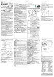
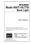
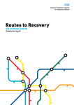
1
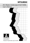
AS-i Master Module User’s Manual (Hardware) A1SJ71AS92 Thank you for buying the Mitsubishi general-purpose programmable logic controller MELSEC-A Series Prior to use, please read both this manual and detailed manual thoroughly and familiarize yourself with the product. MODEL A1SJ71AS92-U-H-JE MODEL 13JQ99 CODE IB(NA)-0800122-B(0406)MEE 2000 MITSUBISHI ELECTRIC CORPORATION z SAFETY PRECAUTIONS z (Read these precautions before using.) When using Mitsubishi equipment, thoroughly read this manual and the associated manuals introduced in this manual. Also pay careful attention to safety and handle the module properly. These precautions apply only to Mitsubishi equipment. Refer to the CPU module user's manual for a description of the PC system safety precautions. These z SAFETY PRECAUTIONS z classify the safety precautions into two categories: "DANGER" and "CAUTION". Procedures which may lead to a dangerous condition and DANGER cause death or serious injury, if not carried out properly. Procedures which may lead to a dangerous condition and CAUTION cause superficial to medium injury, or physical damage only, if not carried out properly. CAUTION may also Depending on circumstances, procedures indicated by be linked to serious results. In any case, it is important to follow the directions for usage. Store this manual in a safe place so that you can take it out and read it whenever necessary. Always forward it to the end user. [DESIGN PRECAUTIONS] CAUTION z Do not bundle AS-i cable together with main circuit or power lines, or lay them close to these lines. As a guide, separate these lines by a distance of at least 100 mm, otherwise malfunctions may occur due to noise. [INSTALLATION PRECAUTIONS] CAUTION z Use the PLC in an environment that conforms to the general specifications in CPU module user's manual. Using the PLC in the environments outside the ranges stated in the general specifications will cause electric shock, fire, malfunction, or damage to/deterioration of the product. z Do not touch conductive parts or electronic components of the module with your bare hands. This could cause malfunction or failure of the module A-1 [INSTALLATION PRECAUTIONS] CAUTION z Insert the module fixing latch on the bottom of the module into the fixing hole of the base unit securely, and use the module fixing hole as the supporting point to install the module. Then tighten the module fixing screw to the specified torque. Incorrect installation with no screws could result in malfunction, failure or fall of the module. Tightening the screw excessively may cause fall, short circuit, or malfunction of the module due to damage of the screw or the module. z Always shut off all phases of the PLC power supply and AS-i power supply externally before mounting or removing the module. Failure to shut off all phases could lead to product damage. [WIRING PRECAUTIONS] DANGER z Switch off all phases of the PLC power supply and AS-i power supply outside the PLC before starting installing or wiring work. If all phases are not switched off, there will be a danger of electric shock or damage to the product. z Always install the terminal covers enclosed with the product before turning ON the power or operating the product after installation or wiring. Failure to install the terminal cover could lead to electric shocks. CAUTION z Always confirm the products terminal layout before wiring to the module. Incorrect wiring could lead to fires or faults. z Tighten terminal screws to the specified torque. If a terminal screw is not tightened to the specified torque, the module may fall out, short circuit, or malfunction. If a terminal screw is tightened excessively, exceeding the specified torque, the module may fall out, short circuit, or malfunction due to breakage of the screw or the module. z Make sure that no foreign matter such as chips or wire offcuts gets inside the module. It will cause fire, failure, or malfunction. z AS-i cables connected to a module must always be run in a duct or held securely using clamps. If a cable is not run in a duct or not held securely using clamps, the cable will sag, move, or be pulled by mistake, which will cause damage to the module and the cable and also malfunctioning due to loose connection of the cable. z When removing the AS-i cable from a module, do not pull it out by the cable. A cable loosen the screws that hold the cable onto the module then remove the cable. If the cable is pulled while it is connected to the module, the module and/or the cable will be damaged and may malfunction due to loose connection of the cable. A-2 Revisions * The manual number is noted at the lower left of the back cover. Print Date *Manual Number Revision Apr.,2000 IB(NA)-0800122-A First edition Jun., 2004 IB(NA)-0800122-B Partial correction SAFETY PRECAUTIONS, Section 3.1, Chapter 5 This manual confers no industrial property rights or any rights of any other kind, nor does it confer any patent licenses. Mitsubishi electric Corporation cannot be held responsible for any problems involving industrial property rights which may occur as a result of using the contents noted in this manual. 2000 MITSUBISHI ELECTRIC CORPORATION A-3 CONTENTS 1. Overview .......................................................................................................1 2. Performance Specifications ..........................................................................1 3. Handing .........................................................................................................2 3.1 Precautions for Handling ..........................................................................2 4. Part Identification Nomenclature ...................................................................3 5. Wiring ............................................................................................................4 5.1 Precautions for Wiring .............................................................................5 5.2 Wiring .......................................................................................................5 6. Outline Dimension Drawings .........................................................................6 6.1 A1SJ71AS92 ............................................................................................6 About the Manuals The following product manuals are available. Please use this table as a reference to request the appropriate manual as necessary. Detailed Manual Manual name AS-i Master Module User's Manual type A1SJ71AS92 Manual No. (Model code) SH-080085 (13JR15) Correspondence to EMC Directives and Low-Voltage Directives For instructions to make the PLC compatible with EMC standards, refer to Chapter 3 "EMC AND LOW-VOLTAGE DIRECTIVE" in PLC CPU User's Manual (Hardware). * If Chapter 3 "EMC AND LOW-VOLTAGE DIRECTIVE" is not provided in the User's Manual (Hardware Section) of the CPU module in use, refer to the Main QnA Series CPU Compatible High-speed Accessing Basic Base Unit Additional Explanation for the Product Conforming to EMC Standards (IB66837) (optional). A-4 1. Overview This manual explains the specifications and names of each parts, etc., of the A1SJ71AS92 model AS-i master module (abberviated as A1SJ71AS92) which are used with AS-i system. 1) The use, cable used and installation position of the A1SJ71AS92 are indicated on the following chart. Use The master of AS-i system Application Main base, Extension base I/O slot 2) Please verify the existence of the following parts after opening the package. a) In the case of A1SJ71LP21 Product name AS-i Master Module A1SJ71AS92 Quantity 1 3) Application CPU A1SJCPU-S3, A1SCPU, A2SCPU, A1SJHCPU, A1SHCPU, A2SHCPU, A2USCPU(S1), A2USHCPU-S1, Q2ASCPU(S1), Q2ASHCPU(S1), Q02CPU-A, Q02HCPU-A and Q06HCPU-A 2. Performance Specification The A1SJ71AS92 performance specifications are shown below. Item Number of AS-i systems Maximum number of AS-i slaves Maximum number of AS-i Input system input/output points Output Specification Two systems 62 (31 × 2 systems) 248 points (124 points × 2 systems) 248 points (124 points × 2 systems) Approx. 5ms (when maximum number of Input/output refresh time input/output points are connected) Communication speed 167kbps Maximum 100m(328.1 ft.)/system (Maximum Transmission distance 300m (984.3 ft.) when two repeaters are used) Bus network type, independent for each Connection type system.(Star, line, tree or ring) APM modulation method (Alternating Pulse Communication method Modulation) Error control method Parity check Flash ROM (for registering slave configuration) Internal memory Number or writes: 10000 times or less Number of occupied input/output points 32 points (I/O assignment: special 32 points) Applicable wire Use AS-i cables R2-3.5, RAV 2-3.5, RAP 2-3.5, RBV 2-3.5, RBP 2Applicable crimp terminal 3.5 (JIS C2805 compliant) 30.5VDC (supplied independently to each system Voltage External from AS-i power supply) power supply Current consumption 70mA/system (TYP 30.5VDC) 5VDC internal current consumption 0.15A Weight 0.30kg For general specifications of the A1SJ71AS92, refer to the users manual for the CPU module that is to be used. 1 3. Handling [INSTALLATION PRECAUTIONS] CAUTION z Use the PLC in an environment that conforms to the general specifications in CPU module user's manual. Using the PLC in the environments outside the ranges stated in the general specifications will cause electric shock, fire, malfunction, or damage to/deterioration of the product. z Do not touch conductive parts or electronic components of the module with your bare hands. This could cause malfunction or failure of the module z Install so that the pegs on the bottom of the module fit securely into the base unit peg holes. The module fixing screws must be tighten by the specified torque. Not installing the module correctly or tightening the screws to the terminal base could result in erroneous operation, damage, or pieces of the product falling. z Always shut off all phases of the PLC power supply and AS-i power supply externally before mounting or removing the module. Failure to shut off all phases could lead to product damage. 3.1 Precautions for handling 1) The main modules case is made of plastic, so do not drop it or subject it to strong impacts. 2) Do not dismount the printed wiring board from the case. It may damage the module. 3) Tighten the module fixing screws, terminal block installation screws and terminal block terminal screws within the following range. Screw position Module fixing screw (M4) Terminal block installation screw Terminal block terminal screw 2 Tightening torque range 78 to 118Nycm 35.3 to 48Nycm 60.8 to 82.3Nycm 4. Part Identification Nomenclature Indicates the name of each part of A1SJ71AS92. A1SJ71AS92 RUN 1) 2) U ASI ERR. MODE 3) SET 4) ASI1+ 1 ASI1+ 2 ASI1- 3 ASI1- 4 ASI2+ 5 ASI2+ 5) 6 ASI2- 7 ASI2- 8 (FG) 9 (FG) 10 A1SJ71AS92 No. Name Details 1) 17-segment LED The operation status of the A1SJ71AS92 is displayed as a value. 2) LED display The operation status of the A1SJ71AS92 is shown by turning ON or OFF. 3) MODE switch This switch is used to change between the protected operation mode and configuration mode. RUN This turns ON when the A1SJ71AS92 is running normally. U ASI The AS-i circuit is sufficiently powered. This LED refers to the AS-i line shown on digit 1. ERR. Configuration error. This LED refers to the AS-i line shown on digit 1. 4) SET switch This switch is used to set or delete the slave address. 5) Terminal block This is connected to the AS-i system with an AS-i cable. 3 5. Wiring DANGER z Switch off all phases of the PLC power supply and AS-i power supply outside the PLC before starting installing or wiring work. If all phases are not switched off, there will be a danger of electric shock or damage to the product. z Always install the terminal covers enclosed with the product before turning ON the power or operating the product after installation or wiring. Failure to install the terminal cover could lead to electric shocks. CAUTION z Always confirm the products terminal layout before wiring to the module. Incorrect wiring could lead to fires or faults. z Tighten terminal screws to the specified torque. If a terminal screw is not tightened to the specified torque, the module may fall out, short circuit, or malfunction. If a terminal screw is tightened excessively, exceeding the specified torque, the module may fall out, short circuit, or malfunction due to breakage of the screw or the module. z Make sure that no foreign matter such as chips or wire offcuts gets inside the module. It will cause fire, failure, or malfunction. z AS-i cables connected to a module must always be run in a duct or held securely using clamps. If a cable is not run in a duct or not held securely using clamps, the cable will sag, move, or be pulled by mistake, which will cause damage to the module and the cable and also malfunctioning due to loose connection of the cable. z Do not bundle AS-i cable together with main circuit or power lines, or lay them close to these lines. As a guide, separate these lines by a distance of at least 100 mm, otherwise malfunctions may occur due to noise. z When removing the AS-i cable from a module, do not pull it out by the cable. A cable loosen the screws that hold the cable onto the module then remove the cable. If the cable is pulled while it is connected to the module, the module and/or the cable will be damaged and may malfunction due to loose connection of the cable. 4 5.1 Precautions for Wiring 1) The overall distance is up to 100m. When using a repeater, the distance can be extended by 100m(328.1ft.) per repeater. Up to two repeaters can be used, so the maximum overall distance is 300m(984.3ft.). 5.2 Wiring Use an AS-i cable to connect the A1SJ71AS92 to the AS-i system. An example of wiring to the A1SJ71AS92 is shown below. (Confirm each module being used for the AS-i power supply and slave terminal layout.) A1SJ71AS92 AS-i power supply AS-i cable AS-i power supply AS-i cable ASI 1+ AS-i cable ASI 1+ Slave ASI 1- ASI 1ASI 2+ ASI 2+ AS-i cable Slave ASI 2ASI 2FG FG *1 *1: When the noise environment is bat, the terminal FG is grounded. 5 6. Outline Dimension Drawings 6.1 A1SJ71AS92 A1SJ71AS92 RUN U ASI ERR. MODE 130 (5.12) SET PCB ASI1+ 1 ASI1+ ASI1- 2 3 ASI1ASI2+ 4 5 ASI2+ ASI2- 6 7 ASI2- 8 (FG) 9 (FG) 10 A1SJ71AS92 6.5 (0.26) 93.6 (3.69) 24.63 (0.97) 34.5 (1.36) Unit:mm (in.) 6 Warranty Mitsubishi will not be held liable for damage caused by factors found not to be the cause of Mitsubishi; machine damage or lost profits caused by faults in the Mitsubishi products; damage, secondary damage, accident compensation caused by special factors unpredictable by Mitsubishi; damages to products other than Mitsubishi products; and to other duties. For safe use y This product has been manufactured as a general-purpose part for general industries, and has not been designed or manufactured to be incorporated in a device or system used in purposes related to human life. y Before using the product for special purposes such as nuclear power, electric power, aerospace, medicine or passenger movement vehicles, consult with Mitsubishi. y This product has been manufactured under strict quality control. However, when installing the product where major accidents or losses could occur if the product fails, install appropriate backup or failsafe functions in the system. Country/Region Sales office/Tel U.S.A Mitsubishi Electric Automation Inc. 500 Corporate Woods Parkway Vernon Hills, IL 60061 Tel : +1-847-478-2100 Brazil MELCO-TEC Rep. Com.e Assessoria Tecnica Ltda. AV. Paulista 1471, Conj. 308, Sao Paulo City, Sao Paulo State, Brazil Tel : +55-11-283-2423 Germany Mitsubishi Electric Europe B.V. German Branch Gothaer Strasse 8 D-40880 Ratingen, GERMANY Tel : +49-2102-486-0 U.K Mitsubishi Electric Europe B.V. UK Branch Travellers Lane, Hatfield, Herts., AL10 8XB,UK Tel : +44-1707-276100 Italy Mitsubishi Electric Europe B.V. Italian Branch Centro Dir. Colleoni, Pal. Perseo-Ingr.2 Via Paracelso 12, 20041 Agrate B., Milano, Italy Tel : +39-039-6053344 Spain Mitsubishi Electric Europe B.V. Spanish Branch Carretera de Rubi 76-80 08190 - Sant Cugat del Valles, Barcelona, Spain Tel : +34-93-565-3131 France Mitsubishi Electric Europe B.V. French Branch 25 Boulevard des Bouvets, F-92741 Nanterre Cedex, France TEL: +33-1-5568-5568 South Africa Circuit Breaker Industries LTD. Tripswitch Drive, Elandsfontein Gauteng, South Africa Tel : +27-11-928-2000 Country/Region Sales office/Tel Hong Kong Ryoden Automation Ltd. 10th Floor, Manulife Tower, 169 Electric Road, North Point, HongKong Tel : +852-2887-8870 China Ryoden Automation Shanghai Ltd. 3F Block5 Building Automation Instrumentation Plaza 103 Cao Bao Rd. Shanghai 200233 China Tel : +86-21-6475-3228 Taiwan Setsuyo Enterprise Co., Ltd. 6F., No.105 Wu-Kung 3rd.RD, Wu-Ku Hsiang, Taipei Hsine, Taiwan Tel : +886-2-2299-2499 Korea HAN NEUNG TECHNO CO.,LTD. 1F Dong Seo Game Channel Bldg., 660-11, Deungchon-dong Kangsec-ku, Seoul, Korea Tel : +82-2-3660-9552 Singapore Mitsubishi Electric Asia Pte, Ltd. 307 ALEXANDRA ROAD #05-01/02, MITSUBISHI ELECTRIC BUILDING SINGAPORE 159943 Tel : +65-6473-2308 Thailand F. A. Tech Co.,Ltd. 898/28,29,30 S.V.City Building,Office Tower 2,Floor 17-18 Rama 3 Road, Bangkpongpang, Yannawa, Bangkok 10120 Tel : +66-2-682-6522 Indonesia P.T. Autoteknindo SUMBER MAKMUR Jl. Muara Karang Selatan Block A Utara No.1 Kav. No.11 Kawasan Industri/ Pergudangan Jakarta - Utara 14440 Tel : +62-21-663-0833 India Messung Systems Put,Ltd. Electronic Sadan NO:111 Unit No15, M.I.D.C BHOSARI,PUNE-411026 Tel : +91-20-712-2807 Australia Mitsubishi Electric Australia Pty. Ltd. 348 Victoria Road, PostalBag, No 2, Rydalmere, N.S.W 2116, Australia Tel : +61-2-9684-7777 HEAD OFFICE : 1-8-12, OFFICE TOWER Z 14F HARUMI CHUO-KU 104-6212, JAPAN NAGOYA WORKS : 1-14, YADA-MINAMI 5-CHOME, HIGASHI-KU, NAGOYA, JAPAN When exported from Japan, this manual does not require application to the Ministry of Economy, Trade and Industry for service transaction permission. Specifications subject to change without notice. Printed in Japan on recycled paper.