1
• SAFETY PRECAUTIONS •
(Read these precautions before using.)
When using Mitsubishi equipment, thoroughly read this manual and the associated manuals introduced in
this manual. Also pay careful attention to safety and handle the module properly.
These precautions apply only to Mitsubishi equipment. Refer to the CPU module user's manual for a
description of the programmable controller system safety precautions.
In this manual, the safety precautions are classified into two levels: "
WARNING" and "
CAUTION".
WARNING
Indicates that incorrect handling may cause hazardous conditions,
resulting in death or severe injury.
CAUTION
Indicates that incorrect handling may cause hazardous conditions,
resulting in minor or moderate injury or property damage.
CAUTION" may lead to
Under some circumstances, failure to observe the precautions given under "
serious consequences.
Observe the precautions of both levels because they are important for personal and system safety.
Make sure that the end users read this manual and then keep the manual in a safe place for future
reference.
[DESIGN PRECAUTIONS]
WARNING
• If a communication error occurs in the AS-i system, the input will turn OFF from the slave having the
communication error.
Output to the slave with communication error will be held or cleared depending on the slave
specifications.
The AS-i system communication error can be confirmed with the buffer memory's List of Active Slaves
(LAS) (15 to 16H, 75 to 76H) and with the input signal Config OK (X4, X9).
Using the above information, configure an interlock circuit on the sequence program so that the system
activates safely.
There is a risk of accidents caused by incorrect outputs or incorrect operations.
• Depending on the unit fault, the input/output could enter the ON state or OFF state.
Provide a circuit for external monitoring for input/output signals that could lead to major accidents.
CAUTION
• Do not bundle AS-i cable together with main circuit or power lines, or lay them close to these lines.
As a guide, separate these lines by a distance of at least 100 mm, otherwise malfunctions may occur
due to noise.
A-1
A-1
[INSTALLATION PRECAUTIONS]
CAUTION
• Use the programmable controller in an environment that conforms to the general specifications in CPU
module user’s manual.
Using the programmable controller in the environments outside the ranges stated in the general
specifications will cause electric shock, fire, malfunction, or damage to/deterioration of the product.
• Do not touch conductive parts or electronic components of the module with your bare hands.
This could cause malfunction or failure of the module
• Insert the module fixing projection into the fixing hole in the base unit and then tighten the module fixing
screw within the specified torque.
Incorrect installation with no screws could result in malfunction, failure or fall of the module.
Tightening the screw excessively may cause fall, short circuit, or malfunction of the module due to
damage of the screw or the module.
• Always shut off all phases of the programmable controller power supply and AS-i power supply
externally before mounting or removing the module.
Failure to shut off all phases could lead to product damage.
[WIRING PRECAUTIONS]
WARNING
• Switch off all phases of the programmable controller power supply and AS-i power supply outside the
programmable controller before starting installing or wiring work.
If all phases are not switched off, there will be a danger of electric shock or damage to the product.
• Always install the terminal covers enclosed with the product before turning ON the power or operating
the product after installation or wiring.
Failure to install the terminal cover could lead to electric shocks.
CAUTION
• Always confirm the products terminal layout before wiring to the module.
Incorrect wiring could lead to fires or faults.
• Tighten terminal screws to the specified torque.
If a terminal screw is not tightened to the specified torque, the module may fall out, short circuit, or
malfunction.
If a terminal screw is tightened excessively, exceeding the specified torque, the module may fall out,
short circuit, or malfunction due to breakage of the screw or the module.
• Make sure that no foreign matter such as chips or wire offcuts gets inside the module.
It will cause fire, failure, or malfunction.
A-2
A-2
[WIRING PRECAUTIONS]
CAUTION
• AS-i cables connected to a module must always be run in a duct or held securely using clamps.
If a cable is not run in a duct or not held securely using clamps, the cable will sag, move, or be pulled by
mistake, which will cause damage to the module and the cable and also malfunctioning due to loose
connection of the cable.
• When removing the AS-i cable from a module, do not pull it out by the cable.
A cable loosen the screws that hold the cable onto the module then remove the cable.
If the cable is pulled while it is connected to the module, the module and/or the cable will be damaged
and may malfunction due to loose connection of the cable.
• Use applicable solderless terminals and tighten them within the specified torque range. If any spade
solderless terminal is used, it may be disconnected when the terminal screw comes loose, resulting in
failure.
[STARTUP/MAINTENANCE PRECAUTIONS]
CAUTION
• Do not touch terminals while the power is ON.
This will cause malfunctions.
• Do not disassemble or modify any module.
This will cause failure, malfunction, injuries, or fire.
• Switch off all phases of the programmable controller power supply and AS-i power supply outside the
programmable controller before cleaning or re-tightening screws. If all phases are not switched off, the
module may fail or malfunction.
If a screw is not tightened securely, the module may fall out, short circuit, or malfunction.
If a screw is tightened excessively, the module may fall out, short circuit, or malfunction due to breakage
of the screw or the module.
• Switch off all phases of the programmable controller power supply and AS-i power supply outside the
programmable controller before mounting or removing the module.
If all phases are not switched off, the module may fail or malfunction.
• Always make sure to touch the grounded metal to discharge the electricity charged in the electricity
charged in the body, etc., before touching the module.
Failure to do say cause a failure or malfunctions of the module.
[DISPOSAL PRECAUTIONS]
CAUTION
• Dispose of this product as industrial waste.
A-3
A-3
• CONDITIONS OF USE FOR THE PRODUCT •
(1) Mitsubishi programmable controller ("the PRODUCT") shall be used in conditions;
i) where any problem, fault or failure occurring in the PRODUCT, if any, shall not lead to any major or
serious accident; and
ii) where the backup and fail-safe function are systematically or automatically provided outside of the
PRODUCT for the case of any problem, fault or failure occurring in the PRODUCT.
(2) The PRODUCT has been designed and manufactured for the purpose of being used in general industries.
MITSUBISHI SHALL HAVE NO RESPONSIBILITY OR LIABILITY (INCLUDING, BUT NOT LIMITED TO
ANY AND ALL RESPONSIBILITY OR LIABILITY BASED ON CONTRACT, WARRANTY, TORT,
PRODUCT LIABILITY) FOR ANY INJURY OR DEATH TO PERSONS OR LOSS OR DAMAGE TO
PROPERTY CAUSED BY the PRODUCT THAT ARE OPERATED OR USED IN APPLICATION NOT
INTENDED OR EXCLUDED BY INSTRUCTIONS, PRECAUTIONS, OR WARNING CONTAINED IN
MITSUBISHI'S USER, INSTRUCTION AND/OR SAFETY MANUALS, TECHNICAL BULLETINS AND
GUIDELINES FOR the PRODUCT.
("Prohibited Application")
Prohibited Applications include, but not limited to, the use of the PRODUCT in;
• Nuclear Power Plants and any other power plants operated by Power companies, and/or any other
cases in which the public could be affected if any problem or fault occurs in the PRODUCT.
• Railway companies or Public service purposes, and/or any other cases in which establishment of a
special quality assurance system is required by the Purchaser or End User.
• Aircraft or Aerospace, Medical applications, Train equipment, transport equipment such as Elevator and
Escalator, Incineration and Fuel devices, Vehicles, Manned transportation, Equipment for Recreation and
Amusement, and Safety devices, handling of Nuclear or Hazardous Materials or Chemicals, Mining and
Drilling, and/or other applications where there is a significant risk of injury to the public or property.
Notwithstanding the above, restrictions Mitsubishi may in its sole discretion, authorize use of the
PRODUCT in one or more of the Prohibited Applications, provided that the usage of the PRODUCT is
limited only for the specific applications agreed to by Mitsubishi and provided further that no special quality
assurance or fail-safe, redundant or other safety features which exceed the general specifications of the
PRODUCTs are required. For details, please contact the Mitsubishi representative in your region.
A-4
A-4
REVISIONS
* The manual number is given on the bottom left of the back cover.
Print Date
Apr., 2000
Oct., 2000
Dec., 2003
Jun., 2004
Sep.,2010
* Manual Number
Revision
SH (NA) 080085-A First edition
SH (NA) 080085-B Addition
Appendix 2, Appendix 3
Correction
Generic Terms and Abbreviations Used in Manual, Section 5.3
SH (NA) 080085-C Correction
SAFETY PRECAUTIONS, Section 2.4, 3.1, 3.4.2
SH (NA) 080085-D Correction
SAFETY PRECAUTIONS, Section 3.3.2, 3.4.2, 4.4.1, 4.5.1, Chapter 5,
Section 5.3
SH(NA)080085-E Change of a term
"PLC" was changed to "programmable controller".
Addition
CONDITION OF USE FOR THE PRODUCT
Correction
SAFETY PRECAUTIONS, Compliance to EMC Directives and LowVoltage Directives, Section 3.1, 4.1, 4.2, 4.4.1, 4.5.1, APPENDIX,
WARRANTY
Japanese Manual Version SH-080084-E
This manual confers no industrial property rights or any rights of any other kind, nor does it confer any patent
licenses. Mitsubishi Electric Corporation cannot be held responsible for any problems involving industrial property
rights which may occur as a result of using the contents noted in this manual.
© 2000 MITSUBISHI ELECTRIC CORPORATION
A-5
A-5
INTRODUCTION
Thank you for purchasing the Mitsubishi general-purpose programmable controller MELSEC-A Series.
Please read this manual thoroughly before starting use to fully comprehend the functions and performance of
the A Series programmable controller, and to ensure correct usage.
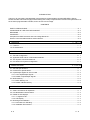
CONTENTS
SAFETY PRECAUTIONS...............................................................................................................................A- 1
CONDITIONS OF USE FOR THE PRODUCT ..............................................................................................A- 4
REVISIONS .....................................................................................................................................................A- 5
CONTENTS.....................................................................................................................................................A- 6
Compliance to EMC Directives and Low-Voltage Directives.........................................................................A- 8
Generic Terms and Abbreviations Used in Manual .......................................................................................A- 8
1. OVERVIEW
1- 1 to 1- 2
1.1 Features .................................................................................................................................................. 1- 2
1.2 Enclosed Parts ........................................................................................................................................ 1- 2
2. SYSTEM CONFIGURATIONS
2.1
2.2
2.3
2.4
2- 1 to 2- 5
General Configuration............................................................................................................................. 2Applicable CPU and No. of Mountable Modules.................................................................................... 2AS-i System Connection Methods.......................................................................................................... 2Precautions for System Configuration.................................................................................................... 2-
3. SPECIFICATIONS
3- 1 to 3- 20
3.1 General Specifications ............................................................................................................................ 33.2 Performance Specifications .................................................................................................................... 33.3 Input/Output Signals for CPU module .................................................................................................... 33.3.1 List of Input/Output Signals.............................................................................................................. 33.3.2 Details of Input/Output Signals ........................................................................................................ 33.4 Buffer Memory......................................................................................................................................... 33.4.1 Buffer Memory List ........................................................................................................................... 33.4.2 Details of Buffer Memory ................................................................................................................. 34. SETTINGS AND PROCEDURES FOR OPERATION
1
1
2
2
3
6
6
8
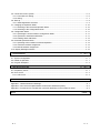
4- 1 to 4- 15
4.1 Outline Procedures for Operation........................................................................................................... 44.2 Part Identification Nomenclature ............................................................................................................ 44.3 Details of LED displays ........................................................................................................................... 44.3.1 17-segment LED .............................................................................................................................. 44.3.2 LED display ...................................................................................................................................... 44.4 Mounting and Installation........................................................................................................................ 44.4.1 Precautions for Handling.................................................................................................................. 44.4.2 Installation Environment................................................................................................................... 4-
A-6
1
2
2
4
A-6
1
2
3
3
4
5
5
5
4.5 Connection to AS-i System..................................................................................................................... 4- 6
4.5.1 Precautions for Wiring...................................................................................................................... 4- 6
4.5.2 Wiring................................................................................................................................................ 4- 7
4.6 Start-up.................................................................................................................................................... 4- 8
4.6.1 Initial Registration of Slaves............................................................................................................. 4- 9
4.7 Changing the Operation Mode .............................................................................................................. 4- 10
4.7.1 Switching to the Protected Operation Mode................................................................................... 4- 10
4.7.2 Switching to the Configuration Mode.............................................................................................. 4- 10
4.8 Configuration Mode................................................................................................................................ 4- 11
4.8.1 Operating the A1SJ71AS92 in Configuration Mode ...................................................................... 4- 11
4.8.2 Operation to Add Slave Addresses ................................................................................................ 4- 11
4.8.3 Deleting Slave Addresses............................................................................................................... 4- 12
4.9 Protected Operation Mode..................................................................................................................... 4- 13
4.9.1 Operating A1SJ71AS92 in Protected Operation............................................................................ 4- 13
4.9.2 Automatic Address Assignment...................................................................................................... 4- 13
4.9.3 Manual Address Assignment .......................................................................................................... 4- 14
4.10 Display Message Numbers.................................................................................................................. 4- 15
5. PROGRAMMING
5- 1 to 5- 2
5.1 System Configuration.............................................................................................................................. 5- 1
5.2 Details of Operation ................................................................................................................................ 5- 1
5.3 Program Examples ................................................................................................................................. 5- 2
6. TROUBLESHOOTING
6- 1 to 6- 2
6.1 Preparatory Check .................................................................................................................................. 6- 1
6.2 Error Check ............................................................................................................................................. 6- 2
6.2.1 LED check ........................................................................................................................................ 6- 2
APPENDIX
A- 1 to A- 4
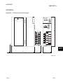
Appendix 1 Outline Dimension Drawings......................................................................................................A- 1
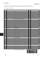
Appendix 2 AS-i Protocol Implementation Conformance Statement (PICS) ...............................................A- 2
Appendix 3 Formula how to calculate the cycle time depending on the number of slaves.........................A- 3
INDEX
A-7
INDEX- 2
A-7
Compliance to EMC Directives and Low-Voltage Directives
When incorporating the Mitsubishi programmable controller into other industrial
machinery or equipment and keeping compliance with the EMC and low voltage
directives, refer to Chapter 3 "EMC Directive and Low Voltage Instruction" of the
User’s Manual (Hardware) for the CPU module used or the programmable
controller CPU supplied with the base unit.
The CE logo is printed on the rating plate of the programmable controller,
indicating compliance with the EMC and low voltage directives.
For making this product compliant with the EMC and low voltage directives,
please refer to Chapter 3 of CPU module User's Manual (Hardware).
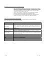
Generic Terms and Abbreviations Used in Manual
Unless noted in particular, the following generic terms and abbreviations are used to explain the
A1SJ71AS92 type AS-i master module in this manual.
Generic term/abbrev.
Details of generic term/abbreviation
A1SJ71AS92
Abbreviation for A1SJ71AS92.
CPU module
Generic term for A1SJCPU-S3, A1SCPU, A2SCPU, A1SJHCPU (S8), A1SHCPU,
A2SHCPU (S1), A2ASCPU (S1/S30), A2USHCPU-S1, Q2ASCPU (S1), Q2ASHCPU (S1),
Q02CPU-A, Q02HCPU-A, Q06HCPU-A, Q02CPU, Q02HCPU, Q06HCPU, Q12HCPU and
Q25HCPU.
Main base unit
Generic term for A1S32B, A1S33B, A1S35B, A1S38B, A1S38HB, QA1S35B and QA1S38B
type main base unit.
Extension base unit
Generic term for A1S52B (S1), A1S55B (S1), A1S58B (S1), A1S65B (S1), A1S68B (S1),
QA1S65B and QA1S68B type extension base unit.
Extension cable
Generic term for A1SC01B, A1SC03B, A1SC07B, A1SC12B, A1SC30B, A1SC60B,
A1SC05NB, A1SC07NB, A1SC30NB, A1SC50NB, QC06B, QC12B, QC30B, QC50B and
QC100B type extension cable.
Data link system
Generic term for MELSECNET, MELSECNETII and MELSECNET/B data link system.
Network system
Generic term for MELSECNET/10 network system.
LAS
Abbreviation for List of Active Slaves.
LDS
Abbreviation for List of Detected Slaves.
LPS
Abbreviation for List of Projected Slaves.
EC flag
Abbreviation for Execution Control flag.
A-8
A-8
1 OVERVIEW
MELSEC-A
1 OVERVIEW
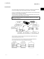
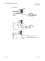
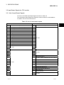
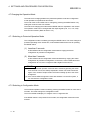
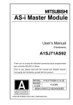
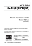
This manual explains the specifications, procedures for operation and troubleshooting
of the A1SJ71AS92 type AS-i master module (hereinafter, A1SJ71AS92).
The AS-i is the abbreviation of the Actuator-Sensor-Interface, and is a network system
specified by the IEC Standards: IEC62026-2.
The A1SJ71AS92 is compatible with the AS-Interface Specification Version 2.04, and
can be used as the master module of the AS-i system.
Refer to IEC 62026-2 for details on the specifications related to the AS-i system
described in this manual.
A1SJ71AS92
AS-i system 1
AS-i cable
AS-i system 2
AS-i cable
AS-i system 1
slave address 2
AS-i system 2
slave address 1
AS-i system 1
AS-i power supply
AS-i system 1
slave address 1
AS-i system 2
slave address 2
AS-i system 2
AS-i power supply
Use AS-i cables, AS-i power supply units and slaves that complies with the ASInterface Specification Version 2.04.
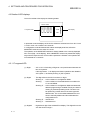
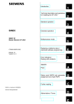
The CPU module transmits and receives the slave's input/output data via the
A1SJ71AS92 buffer memory using the FROM/TO instructions.
A1SJ71AS92
CPU module
Sequence
program
Reception
data
Transmission
data
1-1
FROM
instruction
TO
instruction
Slave
Buffer memory
0 to 7H
Input data
30 to 37H
Output data
1-1
1
1 OVERVIEW
MELSEC-A
1.1 Features
1
The A1SJ71AS92 has the following features.
(1) Automatic slave address assignment function (Automatic address
assignment function)
When a fault occurs in a slave (when one of the set slaves is not recognized), the
A1SJ71AS92 can automatically assign the slave address of a slave similar to the
faulty slave, for which the slave address is set to 0, as the slave address for the
faulty slave.
(2) Maximum number of connected slaves
The A1SJ71AS92 can control up to 31 slave modules per AS-i system. The
A1SJ71AS92 can control two systems.
(The maximum number of input/output points per slave is 4 input points and 4
output points.)
(3) Overall distance
The overall distance is 100m.
Note that the overall distance can be extended to up to 300m by using two
repeaters.
(4) Input/output signal refresh time
The refresh time for the input/output signals is approx. 5ms when using the
maximum number of input/output points.
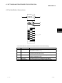
1.2 Enclosed Parts
After opening the A1SJ71AS92 package, confirm that the following products are
enclosed.
Type
Part name
Qty.
A1SJ71AS92
A1SJ71AS92 type AS-i master module
1
Manual
A1SJ71AS92 type AS-i Master Module User's Manual
1
(Hardware)
1-2
1-2
2 SYSTEM CONFIGURATION
MELSEC-A
2 SYSTEM CONFIGURATIONS
The configuration of the programmable controller system that can be combined with
the A1SJ71AS92 is explained in this section.
2
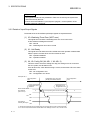
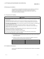
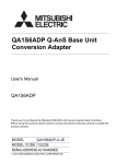
2.1 General Configuration
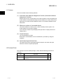
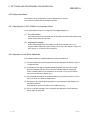
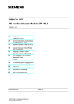
The configuration for assembling the programmable controller into the AS-i system with
the A1SJ71AS92 is shown below.
CPU module
Main base unit
Extension cable
A1SJ71AS92
Extension base unit
AS-i cable
Slave
1
*
*1
Two AS-i systems can be connected to the A1SJ71AS92.
Use AS-i cables, AS-i power supply units and slaves that
complies with the AS-Interface Specification Version 2.04.
AS-i cable
AS-i power supply
Fig. 2.1 System configuration drawing
2-1
2-1
2 SYSTEM CONFIGURATION
MELSEC-A
2.2 Applicable CPU and No. of Mountable Modules
The A1SJ71AS92 can be used with the following CPU modules.
Applicable CPU
No. of mountable modules
A1SJCPU-S3, A1SCPU, A2SCPU
A1SJHCPU (S8), A1SHCPU, A2SHCPU (S1)
2
A2ASCPU (S1/S30), A2USHCPU-S1
1
No limits *
Q2ASCPU (S1), Q2ASHCPU (S1)
Q02CPU-A, Q02HCPU-A, Q06HCPU-A
2
Q02CPU, Q02HCPU, Q06HCPU, Q12HCPU, Q25HCPU *
*1 : The A1SJ71AS92 can be used within the maximum number of input/output point
range of the CPU module in use.
*2 : The A1SJ71AS92 can be mounted only on the extension base unit (QA1S65B,
QA1S68B).
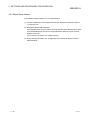
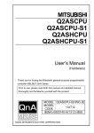
2.3 AS-i System Connection Methods
The following methods can be used to connect the AS-i system.
(1) The star method, line method, tree method or ring method can be
used to connect the AS-i system.
(2) The AS-i system does not require a terminator. The overall
distance is 100m when a repeater is not used, and 300m when two
repeaters are used.
(3) One AS-i power supply unit is connected to the AS-i system. The
power supply can be connected at any place on the AS-i system.
When using a repeater, connect an AS-i power supply unit after the
repeater is connected.
Examples of each connection method are shown below.
(1) Star method
AS-i power supply
S
S: slave
2-2
Power supply
module
CPU module
A1SJ71AS92
S
S
S
Repeater
Repeater
AS-i power
supply
AS-i power
supply
S
S
2-2
2 SYSTEM CONFIGURATION
MELSEC-A
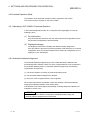
(2) Line method
Power supply
module
CPU module
A1SJ71AS92
AS-i power supply
S
Repeater
S
S
S: slave
S
AS-i power
supply
AS-i power
supply
S
Repeater
(3) Tree method
Power supply
module
CPU module
A1SJ71AS92
AS-i power supply
S: slave
S
S
S
S
Repeater
(4) Ring method
2-3
S
S
S
A1SJ71AS92
S: slave
S
S
Power supply
module
CPU module
AS-i power supply
S
AS-i power
supply
Repeater
S
AS-i power
supply
S
S
(Note)
The system cannot be branched to
a tree connection, etc., from the ring
connection. A partial loop cannot be formed.
A repeater cannot be used.
2-3
2 SYSTEM CONFIGURATION
MELSEC-A
2.4 Precautions for System Configuration
(1) The A1SJ71AS92 can be mounted in a random slot of the base
unit.
Note that when using the Q02CPU, Q02HCPU, Q06HCPU, Q12HCPU or
Q25HCPU module, the A1SJ71AS92 can be mounted only on the extension
base unit (QA1S65B, QA1S68B).
If the A1SJ71AS92 is mounted on an extension base unit (A1S52B (S1),
A1S55B (S1), A1S58B (S1)) to which the power supply module cannot be
mounted, the power supply capacity may be insufficient.
(2) The A1SJ71AS92 can be used as the master station or local
station in a data link system, and as a control station or normal
station in the network system.
The A1SJ71AS92 cannot be used as the remote I/O station in the data link
system or network system.
(3) To use a repeater, check the specification of the slave response
time.
When two repeaters are used in series to extend the system of A1SJ71AS92
(hardware version A), A1SJ71AS92 may not recognize the slave if the slave
response time is too long.
In this case, build the system so that the following equation (standard of As-i Ver.
2.04) is satisfied.
For A1SJ71AS92 (hardware version B or later), build the system so that the
following equations are satisfied.
Slave response time + Repeater's delay + Cable's delay 11 [TBit]
Slave response time + Repeater's delay + Cable's delay 10 [TBit]
(where, in AS-I standard, 1 [TBit (bit time)] = about 6 [µs] is represented.)
For specifications of slave response time, repeater's and cable's delays, contact
each respective manufacturer.
2-4
2-4
2 SYSTEM CONFIGURATION
MELSEC-A
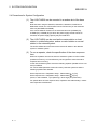
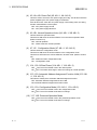
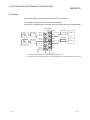
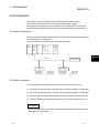
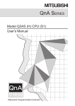
(Calculation example)
100m
100m
100m
A1SJ71
AS92
Repeater
Request
Repeater
Slave
1)
2)
3)
4)
5)
11)
10)
9)
8)
7)
6)
Response
Include the time until the master receives the response from the slave since the master issues the request,
within 10 [TBit] so that the master recognizes the slave.
When each time is as follows with the system configuration as shown in the
above figure:
(a) Repeater's delay (each time for 2), 4), 8), 10)) = about 1.17 [TBit] (per unit)
(b) Cable's delay (each time for 1), 3), 5), 7), 9), 11)) = about 0.00125 [TBit] (per
1m) 100 [m]
(c) Slave response time (6)) = about 3 [TBit]
Slave response time + Repeater's delay + Cable's delay
= 6) + (2) + 4) + 8) + 10)) + (1) + 3) + 5) + 7) + 9) + 11)
= about 8.43 [TBit] 10 [TBit]
Therefore, A1AJ71AS92 can recognize the slave.
On the other hand, when the slave response time (6)) is about 5 [TBit], Slave
response time + Repeater's delay + Cable's delay = 10.43 [TBit] 10 [TBit]
Therefore, A1SJ71AS92 (hardware version A) cannot recognize the slave.
In this case, use any of the following methods.
Reduce the number of repeaters. Or, replace with a repeater with a short delay.
Shorten the cable distance.
Replace with a slave with a quick response time.
A1SJ71AS92 (hardware version B or later) applies to Slave response time +
Repeater's delay + Cable's delay = 10.43 [TBit] 11 [TBit], and, therefore, can
recognize the slave.
2-5
2-5
3 SPECIFICATIONS
MELSEC-A
3 SPECIFICATIONS
The general specifications and performance specifications of the A1SJ71AS92 are
given in this section.
3.1 General Specifications
For the general specifications, refer to the User’s Manual of the CPU module to be
used.
3
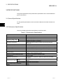
3.2 Performance Specifications
The A1SJ71AS92 performance specifications are shown below.
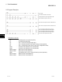
Table 3.1 Performance Specifications
Item
Specification
Number of AS-i systems
Two systems
Maximum number of AS-i slaves
Maximum number of AS-i
system input/output points
62 (31 × 2 systems)
Input
248 points (124 points × 2 systems)
Output
248 points (124 points × 2 systems)
Input/output refresh time
Approx. 5ms (when maximum number of input/output points are
connected)
Communication speed
167kbps
Transmission distance
Maximum 100m/system (Maximum 300m when two repeaters are used)
Connection type
Bus network type, independent for each system.(Star, line, tree or ring)
Communication method
APM modulation method (Alternating Pulse Modulation)
Error control method
Parity check
Internal memory
Flash ROM (for registering slave configuration)
Number or writes: 10000 times or less
Number of occupied input/output points
32 points (I/O assignment: special 32 points)
Applicable wire
Use AS-i cables
Applicable crimp terminal
R2-3.5, RAV 2-3.5, RAP 2-3.5, RBV 2-3.5, RBP 2-3.5 (JIS C2805
compliant)
External power supply
Voltage
30.5VDC (supplied independently to each system from AS-i power
supply)
Current consumption 70mA/system (TYP 30.5VDC)
5VDC internal current consumption
0.15A
Weight
0.30kg
3-1
3-1
3 SPECIFICATIONS
MELSEC-A
3.3 Input/Output Signals for CPU module
3.3.1 List of Input/Output Signals
A list of A1SJ71AS92 input/output signals is shown in Table 3.2.
The input/output signal assignment shows the case for when the A1SJ71AS92 is
mounted in slot 0 of the main base unit.
Table 3.2 List of input/output signals
Signal direction: CPU module
Input
signal
X0
A1SJ71AS92
Signal name
Watchdog Timer Error (WDT error)
Signal direction: CPU module
Output
signal
Unit Ready
Y1
X2
Not used
Y2
X3
Not used
Y3
X4
Config OK AS-i 1
Y4
X5
AS-i Power Fail AS-i 1
Y5
X6
Normal Operation Active AS-i 1
Y6
X7
Configuration Mode AS-i 1
Y7
X8
Not used
Y8
X9
Config OK AS-i 2
Y9
XA
AS-i Power Fail AS-i 2
YA
XB
Normal Operation Active AS-i 2
YB
XC
Configuration Mode AS-i 2
YC
XE
Signal name
Y0
X1
XD
A1SJ71AS92
Not used
YD
Not used
YE
XF
YF
X10
Y10
X11
Y11
X12
Y12
X13
Y13
X14
Y14
Off-line Phase AS-i 1
X15
Y15
Automatic Address Assignment Function Valid AS-i
1
Not used
X16
Y16
Configuration Mode AS-i 1
X17
Y17
Protected Operation Mode AS-i 1
Y18
Off-line Phase AS-i 2
X19
Y19
Automatic Address Assignment Function Valid AS-i
2
X1A
Y1A
Configuration Mode AS-i 2
Protected Operation Mode AS-i 2
X18
Not used
X1B
Y1B
X1C
Y1C Flash ROM write
X1D
Y1D Refresh Instruction
X1E
Y1E
X1F
Y1F
3-2
Not used
3-2
3
3 SPECIFICATIONS
MELSEC-A
Important
The signals indicated as use prohibited in Table 3.2 are used by the system and
cannot be used by the user.
If these are turned ON/OFF by the sequence program, correct operation of the
module cannot be guaranteed.
3.3.2 Details of Input/Output Signals
The details of the A1SJ71AS92 input/output signals are explained below.
(1) X0: Watchdog Timer Error (WDT error)
This signal turns ON when a watchdog timer error occurs due to the
A1SJ71AS92's self-diagnosis function.
OFF : Normal
ON : Watchdog timer error has occurred
(2) X1: Unit Ready
This signal turns ON when the A1SJ71AS92 enters the operation enabled state
after the power is turned ON or the CPU module is reset.
OFF : Operation disabled
ON : Operation enabled
(3) X4, X9: Config OK (X4: AS-i 1, X9: AS-i 2)
This bit is used to check the setting error flag. If a setting error has occurred in
the AS-i system, this bit will turn ON.
If this bit turns ON, check that the wiring is correct, and that the LPS is the same
as the LDS.
OFF : No configuration error
ON : Configuration error found
Example: AS-i 1
No configuration
error
Configuration error
detection
Slave list that differs
from settings
(1DH to 1EH) *2
X4 *2
0
Configuration error occurred
(During slave disconnection)
No configuration
error
Restoration from
configuration error
Bit of corresponding slave number turns ON
0
ON
OFF
ON
Input data of
normally ON input*1
OFF
*1: Shows the timing with the input data when the normally-ON input slave is disconnected.
*2: For AS-i 2 side, read the slave list that differs from settings as 7DH to 7EH, and X4 as X9.
3-3
3-3
3 SPECIFICATIONS
MELSEC-A
(4) X5, XA: AS-i Power Fail (X5: AS-i 1, XA: AS-i 2)
This bit is used to check the AS-i power supply error flag. This bit turns ON if the
power supplied by the AS-i power supply is insufficient.
If this bit turns ON, check the AS-i power supply current rating value, the wiring
and the overall distance of the system.
OFF : AS-i power supply normal
ON : AS-i power supply abnormal
(5) X6, XB: Normal Operation Active (X6: AS-i 1, XB: AS-i 2)
This bit checks the operation state.
This bit turns ON when the A1SJ71AS92 is not in the normal operation state.
(Refer to section 4.6)
OFF : Normal operation
ON : Phase other than normal operation
(6) X7, XC: Configuration Mode (X7: AS-i 1, XC: AS-i 2)
This bit checks the configuration mode.
This bit turns ON when the A1SJ71AS92 is in the configuration mode.
This bit turns OFF when the A1SJ71AS92 is in another mode. (Refer to section
4.6)
OFF : Mode other than configuration mode
ON : Configuration mode
(7) Y14, Y18: Off-line Phase (Y14: AS-i 1, Y18: AS-i 2)
OFF ON: The A1SJ71AS92 is set in the off-line phase.
ON OFF: The status will change in order and change to normal operation.
(8) Y15, Y19: Automatic Address Assignment Function Valid (Y15: ASi 1, Y19: AS-i 2)
This sets the validity of the automatic address assignment function.
OFF: Automatic address assignment function valid
ON: Automatic address assignment function invalid
(9) Y16, Y1A: Configuration Mode (Y16: AS-i 1, Y1A: AS-i 2)
OFF ON: The A1SJ71AS92 is set in the configuration mode.
ON OFF: The A1SJ71AS92 mode does not change.
(10) Y17, Y1B: Protected Operation Mode
OFF ON: The A1SJ71AS92 is set in the protected operation mode.
ON OFF: The A1SJ71AS92 mode does not change.
3-4
3-4
3 SPECIFICATIONS
MELSEC-A
(11) Y1C: Flash ROM write
When this signal turns ON, the configuration data will be written into the flash
ROM.
POINT
(1) FROM/TO instructions to A1SJ71AS92 is not executed at the time of writing in
the flash ROM.
A1SJ71AS92 might make an error if written in the flash ROM while executing
the FROM/TO instruction.
(2) Data can be written to the flash ROM 10,000 times.
If the number of writings exceeds 10,000 times, "F70" (flash ROM write error)
will appear on the A1SJ71AS92's 17-segment LED.
If "F70" appears, a hardware error has occurred, so contact your nearest
Mitsubishi representative.
(12) Y1D: Refresh instruction
This signal determines whether the contents of the "data output to slave" in buffer
memory are valid.
OFF: Invalid (Only OFF data is transmitted to slave)
ON: Valid (The "output data to slave" in buffer memory are transmitted.)
3-5
3-5
3 SPECIFICATIONS
MELSEC-A
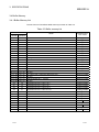
3.4 Buffer Memory
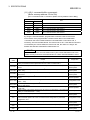
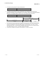
3.4.1 Buffer Memory List
The list of the A1SJ71AS92's buffer memory is shown in Table 3.3.
Table 3.3 Buffer memory list
Address
Details
Read/write from
CPU module
Hexadecimal
Decimal
0H
0
Input data from AS-i 1 slave 1 to 3 and part of EC Flags
1H
1
Input data from AS-i 1 slave 4 to 7
Reading possible
2H
2
Input data from AS-i 1 slave 8 to 11
Reading possible
3H
3
Input data from AS-i 1 slave 12 to 15
Reading possible
4H
4
Input data from AS-i 1 slave 16 to 19
Reading possible
5H
5
Input data from AS-i 1 slave 20 to 23
Reading possible
6H
6
Input data from AS-i 1 slave 24 to 27
Reading possible
7H
7
Input data from AS-i 1 slave 28 to 31
Reading possible
8H to FH
8 to 15
10H
16
11H to 12H
13H to 14H
Reading possible
Not used
EC Flags AS-i 1
Reading possible
17 to 18
LDS AS-i 1
Reading possible
19 to 20
Not used
15H to 16H
21 to 22
LAS AS-i 1
17H to 18H
23 to 24
Not used
19H to 1AH
25 to 26
LPS AS-i 1
1BH to 1CH
27 to 28
Not used
1DH to 1EH
29 to 30
List of slaves with configuration differences AS-i 1
1FH to 24H
31 to 36
Not used
Reading possible
Reading possible
Reading possible
25H to 29H
37 to 41
Command Buffer AS-i 1: <Result>
2AH to 2FH
42 to 47
Not used
30H
48
Output data from AS-i 1 slave 1 to 3
Writing possible
31H
49
Output data from AS-i 1 slave 4 to 7
Writing possible
32H
50
Output data from AS-i 1 slave 8 to 11
Writing possible
33H
51
Output data from AS-i 1 slave 12 to 15
Writing possible
34H
52
Output data from AS-i 1 slave 16 to 19
Writing possible
35H
53
Output data from AS-i 1 slave 20 to 23
Writing possible
36H
54
Output data from AS-i 1 slave 24 to 27
Writing possible
Output data from AS-i 1 slave 28 to 31
Writing possible
37H
55
38H to 48H
56 to 57
Not used
49H to 4AH
73 to 74
LPS AS-i 1
4BH to 54H
75 to 84
Not used
55H to 59H
85 to 89
Command Buffer AS-i 1: <Command>
5AH to 5FH
90 to 95
Not used
3-6
Reading possible
Writing possible
Writing possible
3-6
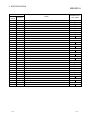
3 SPECIFICATIONS
MELSEC-A
Address
Details
Read/write from
CPU module
Hexadecimal
Decimal
60H
96
Input data from AS-i 2 slave 1 to 3 and part of EC Flags
61H
97
Input data from AS-i 2 slave 4 to 7
Reading possible
62H
98
Input data from AS-i 2 slave 8 to 11
Reading possible
Reading possible
63H
99
Input data from AS-i 2 slave 12 to 15
Reading possible
64H
100
Input data from AS-i 2 slave 16 to 19
Reading possible
65H
101
Input data from AS-i 2 slave 20 to 23
Reading possible
66H
102
Input data from AS-i 2 slave 24 to 27
Reading possible
67H
103
Input data from AS-i 2 slave 28 to 31
Reading possible
68H to 6FH 104 to 111 Not used
70H
112
EC Flags AS-i 2
71H to 72H 113 to 114 LDS AS-i 2
Reading possible
Reading possible
73H to 74H 115 to 116 Not used
75H to 76H 117 to 118 LAS AS-i 2
Reading possible
77H to 78H 119 to 120 Not used
79H to 7AH 121 to 122 LPS AS-i 2
Reading possible
7BH to 7CH 123 to 124 Not used
7DH to 7EH 125 to 126 List of slaves with configuration differences AS-i 2
Reading possible
7FH to 84H 127 to 132 Not used
85H to 89H 133 to 137 Command Buffer AS-i 2: <Result>
Reading possible
8AH to 8FH 138 to 143 Not used
90H
144
Output data from AS-i 2 slave 1 to 3
Writing possible
91H
145
Output data from AS-i 2 slave 4 to 7
Writing possible
92H
146
Output data from AS-i 2 slave 8 to 11
Writing possible
93H
147
Output data from AS-i 2 slave 12 to 15
Writing possible
94H
148
Output data from AS-i 2 slave 16 to 19
Writing possible
95H
149
Output data from AS-i 2 slave 20 to 23
Writing possible
96H
150
Output data from AS-i 2 slave 24 to 27
Writing possible
97H
151
Output data from AS-i 2 slave 28 to 31
Writing possible
98H to A8H 152 to 168 Not used
A9H to AAH 169 to 170 LPS AS-i 2
Writing possible
ABH to B4H 171 to 180 Not used
B5H to B9H 181 to 185 Command Buffer AS-i 2: <Command>
BAH
3-7
186
Writing possible
Not used
3-7
3 SPECIFICATIONS
MELSEC-A
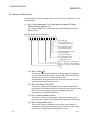
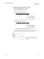
3.4.2 Details of Buffer Memory
The details of each item in the buffer memory, shown in Table 3.3 of section 3.4.1 are
explained below.
(1) AS-i 1 slave addresses 1 to 3 input data, and some EC flags
(Buffer memory address: 0H)
[AS-i 2 slave addresses 1 to 3 input data, and some EC flags (Buffer memory
address: 60H)]
Example: Buffer memory address 0H
Bit 15 14 13 12 11 10 9 8 7 6 5 4 3 2 1 0
Bit 0: Config_OK
0: No configuration error
1: Configuration error occurs
Bit 1: AS-i Power Fail (APF)
0: AS-i Power On (APO)
1: AS-i Power Fail (APF)
Bit 2: Normal Operation Active
0: Normal operation
1: Not normal operation
Bit 3: Configuration Active
0: Not configuration mode
1: Configuration mode
Bit 4 to 7 : Input AS-i 1 slave address 1
Bit 8 to 11 : Input AS-i 2 slave address 2
Bit 12 to 15 : Input AS-i 3 slave address 3
0: OFF
1: ON
(a) Bit 0: Config OK
This bit is for checking the configuration error flag. When a configuration
error occurs in AS-Interface system, this bit is ON. If this bit is ON, check
whether wiring is correct or LPS is the same as LDS.
(Corresponds to input signal X4 and X9. The timing is the same as input
signal X4 and X9. See Section 3.3.2 (3).)
(b) Bit 1: AS-i Power Fail (APF)
This bit is for checking the AS-Interface Power Fail flag. When the AS-i
power supply is insufficient, this bit is ON. If this bit is ON, check the current
rating of AS-i power supply, wiring and, total distance of system.
(Corresponds to input signal X5 and XA.)
(c) Bit 2: Normal Operation Active
This bit is for checking normal operation. When A1SJ71AS92 is not in
normal operation, this bit is ON. (Corresponds to input signal X6 and XB.)
(d) Bit 3: Configuration Active
This bit is for checking configuration mode. When A1SJ71AS92 is in
configuration mode, this bit is ON. When A1SJ71AS92 is in other modes,
this bit is OFF. (Corresponds to input signal X7 and XC.)
3-8
3-8
3 SPECIFICATIONS
MELSEC-A
(e) Bit 4 to 7
: Input AS-i 1 slave address 1
(f) Bit 8 to 11
: Input AS-i 1 slave address 2
(g) Bit 12 to 15 : Input AS-i 1 slave address 3
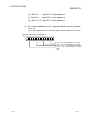
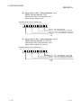
(2) AS-i 1 slave addresses 4 to 31 input data (Buffer memory address:
1H to 7H)
[AS-i 2 slave addresses 4 to 31 input data (Buffer memory address: 61H to 67H)]
Example: Buffer memory address 1H
Bit 15 14 13 12 11 10 9 8 7 6 5 4 3 2 1 0
Bit 0 to 3 : AS-i 1 slave addresses 4 input data
Bit 4 to 7 : AS-i 1 slave addresses 5 input data
Bit 8 to 11 : AS-i 1 slave addresses 6 input data
Bit 12 to 15 : AS-i 1 slave addresses 7 input data
0: OFF
1: ON
3-9
3-9
3 SPECIFICATIONS
MELSEC-A
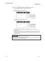
(3) AS-i 1 EC flags (Buffer memory address: 10H)
[AS-i 2 EC flags (Buffer memory address: 70H)]
Example: Buffer memory address 10H
Bit 15 14 13 12 11 10 9 8 7 6 5 4 3 2 1 0
Bit 0: Config_OK
0: No configuration error
1: Configuration error occurs
Bit 1: LDS.0
0: Slave of address 0 is not in list of detected slaves
1: Slave of address 0 is in list of detected slaves
Bit 2: Auto Address Available
0: Automatic address assignment is not allowed.
1: Automatic address assignment is allowed.
Bit 3: Auto Address Assign
0: Automatic address assignment cannot be done.
1: Automatic address assignment can be done.
Bit 4: Configuration Active
0: Not configuration mode
1: Configuration moe
Bit 5: Normal Operation Active
0: Normal operation
1: Not normal operation
Bit 6: AS-i Power Fail (APF)
0: AS-i Power On (APO)
1: AS-i Power Fail (APF)
Bit 7: Off-line Ready
0: Not off-line phase
1: Off-line phase
Bit 8 to 15: Not used
(a) Bit 0: Config OK
Refer to section 3.4.2 (1) (a).
(b) Bit 1: LDS. 0
This bit is for checking the slave having address 0. The slave of address 0
is a reserved slave. When A1SJ71AS92 has detected slave 0, this bit is ON.
(c) Bit 2: Automatic address assignment function valid
This bit is for checking status of the automatic address assignment. When
the automatic address assignment is allowed in the protected operating
mode, this bit is ON.
(d) Bit 3: Auto Address Assign
This bit is for checking if the Automatic Address Assignment is possible.
This is the state in which the automatic address assignment is allowed and
only one of the configured slaves is not recognized in the protected
operating mode. In this case, this bit is ON.
3 - 10
3 - 10
3 SPECIFICATIONS
MELSEC-A
(e) Bit 4: Configuration Active
Refer to section 3.4.2 (1) (d).
(f) Bit 5: Normal Operation Active
Refer to section 3.4.2 (1) (c).
(g) Bit 6: AS-i Power Fail (APF)
Refer to section 3.4.2 (1) (b).
(h) Bit 7: Off-line Ready
This bit is for checking off-line phase. When A1SJ71AS92 is in the off-line
phase, this bit is ON.
(4) AS-i 1 LDS (Buffer memory address: 11H to 12H)
[AS-i 2 LDS (Buffer memory address: 71H to 72H)]
Example: Buffer memory address 11H
Bit 15 14 13 12 11 10 9 8 7 6 5 4 3 2 1 0
Bit 0: Slave No. 0
Bit 1: Slave No. 1
Bit 2: Slave No. 2
Bit 3: Slave No. 3
Bit 15: Slave No. 15
Example: Buffer memory address 12H
Bit 15 14 13 12 11 10 9 8 7 6 5 4 3 2 1 0
Bit 0: Slave No. 16
Bit 1: Slave No. 17
Bit 2: Slave No. 18
Bit 3: Slave No. 19
Bit 15: Slave No. 31
In this list one bit is set for each slave (0 to 31) that is detected by A1SJ71AS92
(through the start up).
When the bit is ON, the system has the slave which corresponds to the bit. If the
bit is OFF, the system does not have the slave which corresponds to the bit.
3 - 11
3 - 11
3 SPECIFICATIONS
MELSEC-A
(5) AS-i 1 LAS (Buffer memory address: 15H to 16H)
[AS-i 2 LAS (Buffer memory address: 75H to 76H)]
Example: Buffer memory address 15H
Bit 15 14 13 12 11 10 9 8 7 6 5 4 3 2 1 0
Bit 0: Slave No. 0
Bit 1: Slave No. 1
Bit 2: Slave No. 2
Bit 3: Slave No. 3
Bit 15: Slave No. 15
Example: Buffer memory address 16H
Bit 15 14 13 12 11 10 9 8 7 6 5 4 3 2 1 0
Bit 0: Slave No. 16
Bit 1: Slave No. 17
Bit 2: Slave No. 18
Bit 3: Slave No. 19
Bit 15: Slave No. 31
In this list one bit is set for each activated slave (1 to 31).
When the bit is ON, the slave corresponding tot he bit is active in the system. If
the bit is OFF, the slave corresponding to the bit is not active in the system.
List of active slaves are detected as follows:
(a) Activation phase
This phase activates the slave(s) which A1SJ71AS92 found in the detection
phase.
(b) In the configuration mode
LAS is same as LDS, i.e. a detected slave always becomes an active slave.
(c) In the protected operating mode
LAS consists of the slave that are ON in both the LDS and PLS, i.e. an
active slave is both a detected slave and a projected slave.
3 - 12
3 - 12
3 SPECIFICATIONS
MELSEC-A
(6) AS-i 1 LPS (Buffer memory address: 19H to 1AH)
[AS-i 2 LPS (Buffer memory address: 79H to 7AH)]
Example: Buffer memory address 19H
Bit 15 14 13 12 11 10 9 8 7 6 5 4 3 2 1 0
Bit 0: Slave No. 0
Bit 1: Slave No. 1
Bit 2: Slave No. 2
Bit 3: Slave No. 3
Bit 15: Slave No. 15
Example: Buffer memory address 1AH
Bit 15 14 13 12 11 10 9 8 7 6 5 4 3 2 1 0
Bit 0: Slave No. 16
Bit 1: Slave No. 17
Bit 2: Slave No. 18
Bit 3: Slave No. 19
Bit 15: Slave No. 31
In this list one bit is status for each projected slave (1 to 31) in A1SJ71AS92. If
the bit is ON, the slave corresponding to the bit is activated in the system. If the
bit is OFF, the slave corresponding to the bit is not activated in the system.
The data in the A1SJ71AS92 flash ROM is displayed when the programmable
controller system power is turned ON.
3 - 13
3 - 13
3 SPECIFICATIONS
MELSEC-A
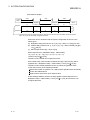
(7) List of slaves that differ from AS-i 1 settings
(Buffer memory address: 1DH to 1EH)
[List of slaves that differ from AS-i 2 settings
(Buffer memory address: 7DH to 7EH)]
Example: Buffer memory address 1DH
Bit 15 14 13 12 11 10 9 8 7 6 5 4 3 2 1 0
Bit 0: Slave No. 0
Bit 1: Slave No. 1
Bit 2: Slave No. 2
Bit 3: Slave No. 3
Bit 15: Slave No. 15
Example: Buffer memory address 1EH
Bit 15 14 13 12 11 10 9 8 7 6 5 4 3 2 1 0
Bit 0: Slave No. 16
Bit 1: Slave No. 17
Bit 2: Slave No. 18
Bit 3: Slave No. 19
Bit 15: Slave No. 31
The result of exclusive OR of the result of the logical sum of LDS, LPS and LAS
is stored in this list. The result of “(LDS | LPS)^LAS” is displayed.
Example:
Bit
LDS(12H)
LAS(16H)
LPS(1AH)
1EH
3 - 14
15
1
0
1
14
1
1
1
13
1
0
0
12 1
1
1
1
0
1
0
LPS,LAS and LPS were collated, so this bit
was turned on due to the disagreement.
0:OFF
1:ON
3 - 14
3 SPECIFICATIONS
MELSEC-A
(8) Data output to AS-i 1 slave addresses 1 to 3
(Buffer memory address: 30H)
[Data output to AS-i 2 slave addresses 1 to 3
(Buffer memory address: 90H)]
Example: Buffer memory address 30H
Bit 15 14 13 12 11 10 9 8 7 6 5 4 3 2 1 0
Bit 0 to 3 : Not used (0000 fixed)
Bit 4 to 7 : AS-i 1 slave addresses 1 output data
Bit 8 to 11 : AS-i 1 slave addresses 2 output data
Bit 12 to 15 : AS-i 1 slave addresses 3 output data
0: OFF
1: ON
(9) Data output to AS-i 1 slave addresses 4 to 31
(Buffer memory address: 31H to 37H)
[Data output to AS-i 2 slave addresses 4 to 31
(Buffer memory address: 91H to 97H)]
Example: Buffer memory address 31H
Bit 15 14 13 12 11 10 9 8 7 6 5 4 3 2 1 0
Bit 0 to 3 : AS-i 1 slave addresses 4 output data
Bit 4 to 7 : AS-i 1 slave addresses 5 output data
Bit 8 to 11 : AS-i 1 slave addresses 6 output data
Bit 12 to 15 : AS-i 1 slave addresses 7 output data
0: OFF
1: ON
3 - 15
3 - 15
3 SPECIFICATIONS
MELSEC-A
(10) AS-i 1 LPS (Buffer memory address: 49H to 4AH)
[AS-i 2 LPS (Buffer memory address: A9H to AAH)]
Example: Buffer memory address 49H
Bit 15 14 13 12 11 10 9 8 7 6 5 4 3 2 1 0
Bit 0: Slave No. 0
Bit 1: Slave No. 1
Bit 2: Slave No. 2
Bit 3: Slave No. 3
Bit 15: Slave No. 15
Example: Buffer memory address 4AH
Bit 15 14 13 12 11 10 9 8 7 6 5 4 3 2 1 0
Bit 0: Slave No. 16
Bit 1: Slave No. 17
Bit 2: Slave No. 18
Bit 3: Slave No. 19
Bit 15: Slave No. 31
In this list, each bit corresponds to the state of the LPS (1 to 31) in the
A1SJ71AS92.
When the A1SJ71AS92 is set to the configuration mode (Y16: ON), and the bit
turns ON, the details will be reflected onto the LPS of the buffer memory 19H to
1AH (79H to 7AH).
POINT
LPS is handled in 32 bit units by A1SJ71AS92.
Even if A1SJ71AS92 writes the data only to buffer memory 49H, the contents of the
buffer memory 4AH also becomes effective.
3 - 16
3 - 16
3 SPECIFICATIONS
MELSEC-A
(11) AS-i 1 command buffer <command>
(Buffer memory address: 55H to 59H)
[AS-i 2 command buffer <command> (Buffer memory address: B5H to B9H)]
Buffer memory address
Item
AS-i 1
AS-i 2
0055H
00B5H
AS-i 1 command buffer <command>
0056H
00B6H
AS-i 1 command buffer <data word 0>
0057H
00B7H
AS-i 1 command buffer <data word 1>
0058H
00B8H
AS-i 1 command buffer <data word 2>
0059H
00B9H
AS-i 1 command buffer <data word 3>
By using the Command Buffer, programmable controller is able to instruct the
A1SJ71AS92. If the programmable controller writes data in Command Buffer
<command> the A1SJ71AS92 reads the Command Buffer <command> and, if
necessary, one to three Data Words. The result is set to “08”. If the desired command
is executed by the A1SJ71AS92, the result is set and, the value is no longer “08”.
Results with data are transmitted in Data Word 0 to 3
POINT
After Data Words are set in the buffer memory first, Command Buffer is set in the
buffer memory when there are Data Words 0 to 3 when Command Buffer is used.
Command
Code
Details
1
Writes data word 0 to the actual parameter * in the AS-i slave n (n = “Command
Code”). And reads the actual parameter form AS-i slave n to data word 0.
Reads the actual parameter *1 from AS-i slave n (n = “Command Code” - 40H) to data
41 to 5FH
word 0.
Writes data word 0 to permanent parameter *1 in the AS-i slave n (n = “Command
91 to 9FH
Code” - 80H).
Reads the permanent parameter *1 from AS-i slave n (n = “Command Code” - C0H) to
C1 to DFH
data word 0.
Reads actual configuration *2 from AS-i slave n (n = “Command Code” - 100H) to data
101 to 11FH
word 0.
Writes data word 0 to permanent configuration *3 in the AS-i slave n (n = “Command
141 to 15FH
Code” – 140H)
Reads the permanent configuration *3 from AS-i slave n (n = “Command Code” 181 to 91FH
180H) to data word 0.
Reads the counter of APF from AJ71AS92 to Data Word 0. And clear this value. (AS-i
1C0H
Power Fail)
Reads counter of erroneous answers from AS-i slave n to Data Word 0. And clear this
1C1 to 1DFH
value. (n = “Command Code” – 1C0H)
01 to 1FH
Usage state
Normal operation
Normal operation,
Off-line phase
Normal operation,
Off-line phase
Normal operation,
Off-line phase
Normal operation
Configuration mode
Normal operation,
Off-line phase
Normal operation
Normal operation
200H
Change AS-i slave (LPS) with address n to m. (n = Data Word 0, m = Data Word 1).
Normal operation,
Off-line phase
201H
Store actual AS-i configuration
<This command copies LAS to LPS. And store actual configuration to permanent
configuration, too.>
Configuration mode
202H
Store actual AS-i parameters to permanent parameter.
Normal operation,
Off-line phase
203H
Validation/invalidation of SET switch and MODE switch, 0: Valid (default), 1: Invalid *4 Normal operation
204H
Read list of corrupted slaves from A1SJ71AS92 to Data Word 0 and 1, And clear this Normal operation,
list.
Off-line phase
3 - 17
3 - 17
3 SPECIFICATIONS
MELSEC-A
*1 : The meaning of this parameter is slave’s parameter bits.
Actual parameter
Parameter of target slave
Permanent parameter
Sets slave parameter
*2 : The meaning of this parameter is slave’s parameter bits. This contains the actual copies of the
input/output configuration and the identification code of all slaves, determined by reading this data from
the slaves. The configuration data of inactive slave is set to default values (“FF <Hex>”).
Actual configuration
I/O code, ID code held by slave
Permanent configuration
I/O code, ID code held by master
Lower-order 8 bits
High-order 8 bits
Not used
High-order 4 bits
Lower-order 4 bits
ID code
I/O code
*3 : This contains the projected input/output configuration and identification code of all slaves determined
4
*
by the slave configuration of the A1SJ71AS92 using the Command Code “141 to 15FH” or by the
Command Code “201FH”. The permanent configuration data of slaves that are not projected shall be
set to default values (“FF <Hex>”). This data is stored in Flash ROM.
: It is effective/is nullified this Command Code regardless of 1 system or 2 systems.
3 - 18
3 - 18
3 SPECIFICATIONS
MELSEC-A
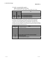
(12) AS-i 1 command buffer <result>
(Buffer memory address: 25H to 29H)
[AS-i 2 command buffer <result> (Buffer memory address: 85H to 89H)]
Buffer memory address
Item
AS-i 1
AS-i 2
0025H
0085H
AS-i 1 command buffer <result>
0026H
0086H
AS-i 1 command buffer <data word 0>
0027H
0087H
AS-i 1 command buffer <data word 1>
0028H
0088H
AS-i 1 command buffer <data word 2>
0029H
0089H
AS-i 1 command buffer <data word 3>
By using the Command Buffer, programmable controller is able to instruct the
A1SJ71AS92. If the programmable controller writes data in Command Buffer
<command> the A1SJ71AS92 reads the Command Buffer <command> and, if
necessary, one to four Data Words. The result is set to “08”. If the desired command is
executed by the A1SJ71AS92, the result is set and, the value is no longer “08”. Results
with data are transmitted in Data Word 0 to 3
Results value
3 - 19
Details
00
Command did not execute.
01
OK (Command executed.)
02
The address of the Slave which wants to change does not exist.
03
A slave already exists in address 0.
04
This address already has a slave.
05
This slave cannot be deleted.
06
This slave address cannot be set.
07
The slave address cannot be written to the slave’s EEPROM.
08
Command Word pending
09
The Command Word not recognized.
0A
The value of Data Word exceeds the range of setting.
3 - 19
3 SPECIFICATIONS
MELSEC-A
MEMO
3 - 20
3 - 20
4 SETTINGS AND PROCEDURES FOR OPERATION
MELSEC-A
4 SETTINGS AND PROCEDURES FOR OPERATION
The procedures, names of each part, installation, connection to the AS-i system and
settings for using the AS-i system with the A1SJ71AS92 are explained in this section.
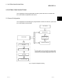
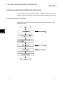
4.1 Outline Procedures for Operation
The procedures for using the A1SJ71AS92 with the AS-i system are shown in the
following flow chart.
4
4-1
4-1
4 SETTINGS AND PROCEDURES FOR OPERATION
MELSEC-A
4.2 Part Identification Nomenclature
A1SJ71AS92
RUN
1)
2)
U ASI
ERR.
MODE
3)
SET
4)
ASI1+
4
1
ASI1+
ASI1-
2
3
ASI1ASI2+
4
5
ASI2+
ASI2-
5)
6
7
ASI2-
8
(FG)
9
(FG)
10
A1SJ71AS92
• The terminal block has two FG terminals that are connected internally.
No.
Name
Details
1)
17-segment LED
The operation status of the A1SJ71AS92 is displayed as a
2)
LED display
The operation status of the A1SJ71AS92 is shown by turning
value. (Refer to section 4.3.1.)
ON or OFF. (Refer to section 4.3.2.)
3)
MODE switch
This switch is used to change between the protected operation
mode and configuration mode.
4-2
4)
SET switch
This switch is used to set or delete the slave address.
5)
Terminal block
This is connected to the AS-i system with an AS-i cable.
4-2
4 SETTINGS AND PROCEDURES FOR OPERATION
MELSEC-A
4.3 Details of LED displays
The A1SJ71AS92 LEDs display the following details.
A1SJ71 AS92
RUN
17-segment LED
Dig
Dig
Dig
Dig
it1
it2
it3
it4
U ASI
LED display
ERR.
In protected mode the displays of the A1SJ71AS92 are switched over from AS-i circuit
1 to AS-i circuit 2 in a measure of 5 seconds.
In configuration mode all detected AS-i slaves are displayed at first, before the
MODE/SET switches to the other AS-i circuit.
The operation of the MODE/SET switches is always related to the currently displayed
AS-i circuit (Digit 1 of the display). After a MODE/SET switch was pressed the display
stays with the respective AS-i circuit until the operation is finished or the operator has
not interfered for 10 seconds.
4.3.1 17-segment LED
4-3
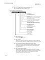
(1) Digit1
: AS-i 1/ AS-i 2. Switching of Digit2 to 4 and push buttons between the
two AS-i systems.
If this digit shows ‘1’, all displays and button operations are related to
AS-i system 1, otherwise (showing ‘2’) AS-i system 2.
(2) Digit2
: This digit refers to the AS-i line shown on digit 1.
Showing ‘C’ : A1SJ71AS92 is in Configuration Mode
Showing ‘ ’ : A1SJ71AS92 is in Protected Mode but conditions for
‘P’ are not fulfilled.
Showing ‘P’ : A1SJ71AS92 is in Configuration Mode and automatic
address programming is enabled. Exactly one slave is
missing in protected operating mode. The slave can
be replaced by another slave of the same type with
address zero. The A1SJ71AS92 addresses the new
slave to the faulty address and thus eliminates the
configuration error.
Showing ‘E’ : Internal error
Showing ‘F’ : Hardware error
(3) Digit3/4
: Higher/lower digit of the Address/Error display. This digit refers to the
AS-i line shown on digit 1.
4-3
4 SETTINGS AND PROCEDURES FOR OPERATION
MELSEC-A
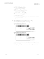
4.3.2 LED display
RUN
U ASI
ERR.
4-4
: This turns ON when the A1SJ71AS92 is running normally.
: The AS-i circuit is sufficiently powered. This LED refers to the AS-i line
shown on digit 1.
: Configuration error. This LED refers to the AS-i line shown on digit 1.
4-4
4 SETTINGS AND PROCEDURES FOR OPERATION
MELSEC-A
4.4 Mounting and Installation
The precautions to be observed when handling the A1SJ71AS92 from unpacking to
installation, and the installation environment are explained in this section.
Refer to the User's Manual of the CPU module being used for details on the
A1SJ71AS92 mounting and installation.
4.4.1 Precautions for Handling
CAUTION
• Use the programmable controller in an environment that conforms to the general specifications in CPU
module user’s.
Using the programmable controller in the environments outside the ranges stated in the general
specifications will cause electric shock, fire, malfunction, or damage to/deterioration of the product.
• Insert the module fixing projection into the fixing hole in the base unit and then tighten the module fixing
screw within the specified torque.
Incorrect installation with no screws could result in malfunction, failure or fall of the module.
Tightening the screw excessively may cause fall, short circuit, or malfunction of the module due to
damage of the screw or the module.
• Always shut off all phases of the programmable controller power supply and AS-i power supply
externally before mounting or removing the module.
Failure to shut off all phases could lead to product damage.
• Do not touch conductive parts or electronic components of the module with your bare hands.
This could cause malfunction or failure of the module
(1) The module case and terminal block are made of resin, so take care not to drop or
apply strong impacts.
(2) Tighten the module mounting screws, terminal block installation screws and
terminal block terminal screws within the following range.
Screw position
Module mounting screw (M4)
Terminal block installation screw
Terminal block terminal screw
Tightening torque range
78 to 118 N⋅cm
35.3 to 48 N⋅cm
60.8 to 82.3 N⋅cm
4.4.2 Installation Environment
Refer to the User's Manual of the CPU module being used for details on the installation
environment.
4-5
4-5
4 SETTINGS AND PROCEDURES FOR OPERATION
MELSEC-A
4.5 Connection to AS-i System
The items to observe when connecting the A1SJ71AS92 to the AS-i system, and the
wiring methods are explained in this section.
4.5.1 Precautions for wiring
WARNING
• Switch off all phases of the programmable controller power supply and AS-i power supply outside the
programmable controller before starting installing or wiring work.
If all phases are not switched off, there will be a danger of electric shock or damage to the product.
• Always install the terminal covers enclosed with the product before turning ON the power or operating
the product after installation or wiring.
Failure to install the terminal cover could lead to electric shocks.
CAUTION
• Always confirm the products terminal layout before wiring to the module.
Incorrect wiring could lead to fires or faults.
• Tighten terminal screws to the specified torque.
If a terminal screw is not tightened to the specified torque, the module may fall out, short circuit, or
malfunction.
• Make sure that no foreign matter such as chips or wire offcuts gets inside the module.
It will cause fire, failure, or malfunction.
• AS-i cables connected to a module must always be run in a duct or held securely using clamps.
If a cable is not run in a duct or not held securely using clamps, the cable will sag, move, or be pulled by
mistake, which will cause damage to the module and the cable and also malfunctioning due to loose
connection of the cable.
• Do not bundle AS-i cable together with main circuit or power lines, or lay them close to these lines.
As a guide, separate these lines by a distance of at least 100 mm, otherwise malfunctions may occur
due to noise.
• When removing the AS-i cable from a module, do not pull it out by the cable.
A cable loosen the screws that hold the cable onto the module then remove the cable.
If the cable is pulled while it is connected to the module, the module and/or the cable will be damaged
and may malfunction due to loose connection of the cable.
(1) The overall distance is up to 100m.
When using a repeater, the distance can be extended by 100m per repeater.
Up to two repeaters can be used, so the maximum overall distance is 300m.
4-6
4-6
4 SETTINGS AND PROCEDURES FOR OPERATION
MELSEC-A
4.5.2 Wiring
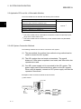
Use an AS-i cable to connect the A1SJ71AS92 to the AS-i system.
An example of wiring to the A1SJ71AS92 is shown below.
(Confirm each module being used for the AS-i power supply and slave terminal layout.)
A1SJ71AS92
AS-i
power
supply
AS-i
power
supply
AS-i cable
ASI 1+
ASI 1AS-i cable
AS-i cable
ASI 1+
ASI 2+
Slave
ASI 1ASI 2+
AS-i cable
Slave
ASI 2ASI 2FG
FG *1
*2
*1 : When the noise environment is bad, the terminal FG is grounded.
*2 : The terminal of the same signal name is connected internally with a right terminal and a left terminal.
4-7
4-7
4 SETTINGS AND PROCEDURES FOR OPERATION
MELSEC-A
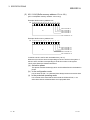
4.6 Start-Up
When the programmable controller power is turned ON, the A1SJ71AS92 will turn ON
the 17-segment LED and all LED displays for approx. one second. After that, the LED
display will show the flag state. The 17-segment LED will show the AS-i system state.
The normal operations include the protected operation mode and configuration mode.
If there is a slave that can communicate with the A1SJ71AS92 during the start up, the
A1SJ71AS92 will enter the mode registered in the flash ROM.
The protected operation mode and configuration mode can be changed by operating
the A1SJ71AS92 switch or writing a command from the CPU module. (Refer to section
4.7.)
(1) Configuration mode
This mode communicates without registering the slave configuration.
The slave address is set with this mode.
Communication is carried out with all detected saves, excluding the slave
detected as slave address 0.
(2) Protected operation mode
This mode communicates after registering the slave configuration.
Communication is carried out only with the slave for which the registered
confirmation and LDS match and the slave that matches the configuration data
set by the actual configuration data.
4-8
4-8
4 SETTINGS AND PROCEDURES FOR OPERATION
MELSEC-A
4.6.1 Initial Registration of Slaves
The method for registering the slave detected by the A1SJ71AS92 in the normal
operation is explained in this section.
The slave is registered into the A1SJ71AS92 with steps (1) and (2) below.
Note that if the power is reset or if the CPU is reset, the data registered in the
A1SJ71AS92 will be cleared.
To prevent the data from being cleared, carry out step (3). The data will be written into
the A1SJ71AS92's flash ROM.
To start in the configuration mode when the power is turned ON, skip step (1) and start
from step (2).
(1) Press the MODE switch for 5 or more seconds. (Enter the configuration mode.)
(2) Press the MODE switch again for 5 or more seconds. (Enter the protected
operation mode.)
The slave configuration will be registered in the protected operation mode.
(3) The CPU module is put into the state of STOP, and press the MODE switch and
SET switch simultaneously for 5 seconds. (Register into the flash ROM.)
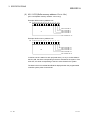
When A1SJ71AS92 completes registration, 17-segment LED displays "OK", other
LED are turned off and start from an offline phase again.
The next time the power is turned ON or when the CPU module is reset, the
communication will be carried out with the contents registered in the flash ROM.
POINT
(1) Please put the CPU module into the state of STOP at the time of writing in flash
ROM.
A1SJ71AS92 might make an error if the slave composition when the CPU
module is RUN is written in flash ROM.
(2) Data can be written to the flash ROM 10,000 times.
If the number of writings exceeds 10,000 times, "F70" (flash ROM write error)
will appear on the A1SJ71AS92's 17-segment LED.
If "F70" appears, a hardware error has occurred, so contact your nearest
Mitsubishi representative.
4-9
4-9
4 SETTINGS AND PROCEDURES FOR OPERATION
MELSEC-A
4.7 Changing the Operation Mode
The method for changing between the protected operation mode and configuration
mode operations is explained in this section.
The mode of the A1SJ71AS92 can be changed by pressing the MODE switch or by
setting the mode from the CPU module.
The method of changing the mode with the MODE switch is explained in this section.
The operation mode can be changed with the output signals (Y16, Y17, Y1A, Y1B)
from the CPU module. (Refer to section 3.3.)
4.7.1 Switching to Protected Operation Mode
The configuration mode is ended by pressing the MODE switch. The mode changes to
protected operating mode. At this time, A1SJ71AS92 follows these rules for pressing
the MODE switch.
(1) Less than 5 seconds
A1SJ72AS92 exits the configuration mode without copying the actual
configuration to permanent configuration.
(2) More than 5 seconds
A1SJ71AS92 exits the configuration mode simultaneously copying the actual
configuration to permanent configuration. At this time, A1SJ71AS92 stores this
configuration to LPS, and 17-segment LED’s Digit2 is turned off, too.
POINT
(1) When the protected operation mode has been entered by pressing the switch
for 5 seconds or more, the startup explained in section 4.6 will be carried out
again. Thus, the slave output will turn OFF when starting up due to the mode
changeover.
(2) If the A1SJ71AS92 recognizes a slave with address 0 on the AS-i system, it
can not leave the configuration mode.
4.7.2 Switching to Configuration Mode
The Protected operation mode is ended by pressing the MODE switch for more than 5
seconds. The mode changes to Configuration mode.
The A1SJ71AS92 will display "C" at digit 2 of the 17-segment LED.
If the MODE switch is not pressed for 5 seconds, the configuration mode will not be
entered.
4 - 10
4 - 10
4 SETTINGS AND PROCEDURES FOR OPERATION
MELSEC-A
4.8 Configuration Mode
The operation of the configuration mode is explained in his section.
This mode is for setting the slave address number.
4.8.1 Operating the A1SJ71AS92 in Configuration Mode
In the configuration mode, the 17-segment LED’s Digit2 displays “C”.
(1) For active slave
All recognized slave are activated with the exception of slave 0 when desired and
actual configurations do not match.
(2) Displayed message
A1SJ71AS92 displays the slave address of all slaves entered in the in 17segment LED’s Digit3/4 at a speed of two per second. If the display is empty, the
list is empty, i.e. no slaves were recognized.
4.8.2 Operation to Add Slave Addresses
This operation assign an available address to slave with address 0.
(1) The slave addresses of all recognized slaves are displayed one after the other in
17-segment LED.
(2) To display the next higher available operating address, press the SET switch.
Each time pressing the SET switch, the next available address is displayed.
If SET or MODE switch is not pressed for 10 seconds or more, A1SJ71AS92
returns to the state of the display of (1).
(3) Set the displayed address as the target address by pressing the switch for more
than 5 seconds. The address display blinks.
(4) Pressing the SET switch again reprograms a connected slave with address 0 to
the blinking address.
(The address is stored in the slave's non-volatile memory.)
(5) If error code did not display, the 17-segment LED displays the list of detected
slaves again as described.
4 - 11
4 - 11
4 SETTINGS AND PROCEDURES FOR OPERATION
MELSEC-A
4.8.3 Delete Slave Address
This operation assign address 0 to a recognized slave.
(1) The slave addresses of all recognized slaves are displayed one after the other in
17-segment LED.
(2) Display the deleted Slave address.
Pressing SET switch for more than 5 seconds while the slave address which wants
to be deleted displayed, this slave is reprogrammed to address 0 again, and the
Digit3/4 shows “00”.
("0" is stored in the slave's non-volatile memory.)
(3) When releasing the switch, the 17-segment LED continues to display the list of
detected slaves.
4 - 12
4 - 12
4 SETTINGS AND PROCEDURES FOR OPERATION
MELSEC-A
4.9 Protected Operation Mode
The operation of the protected operation mode is explained in this section.
This mode is used to normally run the A1SJ71AS92.
4.9.1 Operating A1SJ71AS92 in Protected Operation
In the Protected Operation mode, the 17-segment LED’s Digit2 lights off. And, the
following is done.
(1) For active slave
Only slaves that are entered on the LPS and whose actual configurations match
the permanent configurations will be activated.
(2) Displayed message
The display is either blank or displays the address of faulty assignment.
If the SET switch is pressed in protected operating mode while there is not actual
configuration error, the last slave address which caused an configuration error is
displayed, or “39” is displayed.
4.9.2 Automatic Address Assignment
The automatic address programming is A1SJ71AS92 allocate the address which
automatically fails in address 0 when one of the configured slaves is not recognized in
the protected operating mode. For automatic address programming, the following
requirements are necessary.
(1) The A1SJ71AS92 is necessary in protected operating mode.
(2) The automatic address assignment is allowed.
(3) Only one of the configured slaves is not recognized.
When these requirements are fulfilled, a slave with address 0 will be automatically
assigned the operating address of the missing slave.
If the address is not to be assigned automatically, manually assign the addresses as
explained in section 4.9.3.
POINT
If the two slaves have different configuration data (different slave type), the
automatic address assignment is not executed.
4 - 13
4 - 13
4 SETTINGS AND PROCEDURES FOR OPERATION
MELSEC-A
4.9.3 Manual Address Assignment
If several slaves fail, they cannot be replaced automatically by the A1SJ71AS92. Set
their necessary addresses manually. If you do not want to set their addresses via CPU
module, you can set them with the switch and the 17-segment LED. In the protected
operating mode, wrong assignments are displayed as errors.
The latter method is explained in this section. For the former method, use the
command buffer command code "200". (Refer to section 3.4.2 (11).)
An incorrect assignment in the protected operation mode will be indicated as an error.
(1) By pressing the SET switch, you can display all faulty assignments one after the
other.
(2) By pressing the SET switch for more than 5 seconds, you can select the currently
displayed address as a potential target address, and the display starts to blink.
If the faulty slave was previously replaced by a slave with address 0, the new slave
can now be programmed for the blinking address by pressing the SET switch
again. As a requirement, the new slave’s configuration data must match the
configuration data for the blinking address.
(3) After the address has been successfully set, the next faulty assignment is
displayed or the display erased.
4 - 14
4 - 14
4 SETTINGS AND PROCEDURES FOR OPERATION
MELSEC-A
4.10 Display Message Numbers
The A1SJ71AS92 indicates the A1SJ71AS92 state with the following numbers on the
17-segment LED.
No.
0 to 31
Details
Slave address
39
The last reason for setting Config_OK to zero was entering offline Phase
40
A1SJ71AS92 is in offline phase
41
A1SJ71AS92 is in detection phase
42
A1SJ71AS92 is in activation phase
F50
Fatal hardware error : Consult Mitsubishi representative.
F70
Fatal hardware error : The Flash ROM cannot be written to. Consult Mitsubishi representative.
F72
Fatal hardware error : Consult Mitsubishi representative.
F73
Fatal hardware error : Consult Mitsubishi representative.
E51
Internal error
: There are too many FROM/TO commands, or the command execution interval is
short. Correct the sequence program.
E52
Internal error
: Consult Mitsubishi representative.
E53
Internal error
: Consult Mitsubishi representative.
E80
Slave with address zero detected.
The system attempted to exit the configuration mode with a slave zero or the user tried to change a slave
address while a slave with address zero was connected.
E81
General error while changing a slave address.
E82
Front panel operation blocked. Until the next power-up the only way of accessing the A1SJ71AS92 is via the
programmable controller interface.
E90
Error while changing a slave address in protected operating mode. No slave with address 0 present.
E91
Error while changing slave address. Target address is already occupied.
E92
Error while changing slave address. New address could not be set.
E93
Error while changing slave address. New address could only be stored volatile in the slave.
E94
Error while changing slave address in protected operating mode. Slave has wrong configuration information.
E95
Error while changing slave address in protected operating mode. The configuration error is cause by one
slave too many.
PROG
OK
XXXX
4 - 15
Flash ROM is being written. (Because writing will be completed in a short time, this message is hardly
displayed in 17-segment LED.)
Flash ROM writing completion.
Display test while starting up the A1SJ71AS92.
4 - 15
5 PROGRAMMING
MELSEC-A
5 PROGRAMMING
The program used to exchange the slave input/output information with the
A1SJ71AS92 is explained in this section with a programming example.
When applying the following program examples to the actual system, make sure to
examine the applicability and confirm that it will not cause system control problems.
5.1 System Configuration
With this program example, the information in the slave input/output is exchanged with
the following system configuration.
The A1SJ71AS92 is mounted in slot 0 of the main base unit.
CPU
module
A1SJ71
AS92
to
Input
module
X/Y0
to 1F
to
Output
module
Y90
to 9F
X50
to 5F
AS-i 1 side
AS-i cable
Slave address 4
Slave address 4
4 input points
4 output points
5
AS-i power supply
Slave address 5
CPU module
Y90 to Y93
X50 to X53
Slave address 5
4 input points
4 output points
CPU module
Y94 to Y97
X54 to X57
5.2 Details of Operation
The following operations are carried out with the system shown in section 5.1.
(1) The CPU module inputs X50 to X53 are output to the slave address 4 output data.
(2) The CPU module inputs X54 to X57 are output to the slave address 5 output data.
(3) The slave address 4 input data is output to the CPU module outputs Y90 to Y93.
(4) The slave address 5 input data is output to the CPU module outputs Y94 to Y97.
REMARK
Even if a configuration error occurs, the input/output control will be executed to the
slave that can communicate.
5-1
5-1
5 PROGRAMMING
MELSEC-A
5.3 Program Examples
LAS is read.
The refresh instruction is turned ON.
EC flag and slave 4 and 5 input data are read.
The input data is output to Y90 to Y97.
X50 to X53 are output to the slave 4 data bits 0 to 3.
X54 to X57 are output to the slave 5 data bits 0 to 3.
If a communication disabled slave is used for
slave 4, the output to the slave will be stopped.
If a communication disabled slave is used for
slave 5, the output to the slave will be stopped.
The slave 4 and 5 output data is written.
5
Explanation of devices
X0
X1
X5
X6
X7
M104
M105
M200 to M203
M204 to M207
M300
M316 to M319
M320 to M323
5-2
:
:
:
:
:
:
:
:
:
:
:
:
Watchdog timer error (Normally OFF)
Unit ready (Normally ON)
AS-i 1 AS-i Power Fail (Normally OFF)
AS-i 1 Normal Operation Active (OFF during normal operation)
AS-i 1 configuration mode (OFF in other than configuration mode)
ON when slave address 4 can communicate
ON when slave address 5 can communicate
Data output to slave address 4
Data output to slave address 5
Configuration OK on AS-i 1 side (OFF during normal operation)
Data input from slave address 4
Data input from slave address 5
5-2
6 TROUBLESHOOTING
MELSEC-A
6 TROUBLESHOOTING
The troubleshooting methods to be taken when a fault occurs in the A1SJ71AS92 are
explained in this section.
6.1 Preliminary Checks
First check the following items when checking the A1SJ71AS92.
(1) Check “RUN” and “U ASI” LED.
• If “RUN” LED of A1SJ71AS92 is OFF, check whether the power supply is
supplied to programmable controller.
•If “U ASI” LED is OFF, check the current rating of AS-i power supply, wiring and,
total distance of system.
(2) Check the 24VDC power supply for slave.
If whether this power supply capacity is not enough or miss-wiring is, the slave is
not normal operation.
(3) Check “ERR.” LED.
• If “ERR.” LED is ON, check the wiring about the slave.
6
(4) Check total slave number.
• If total slave number is more than 32, please remove an unnecessary slave and
adjust the number of total slaves to 31 or less.
(5) Check whether it is an intended slave configuration.
• If it is not so, please remake slave configuration.
(6) Check total extension distance
• The total extension distance must not exceed 100m. however, when the
repeater is used, it is possible to extend by 100m repeater. Repeaters can be
used up to two system.
6-1
6-1
6 TROUBLESHOOTING
MELSEC-A
6.2 Error Checking
If the A1SJ71AS92 does not seen to operate normally, check the following items.
6.2.1 LED Check
Check the status of the LEDs for theA1SJ71AS92 as follows.
(1) Check the status of the “RUN” LED
Status
Details
Lit.
There is a power supply of programmable controller.
Off
Check does the power supply of programmable controller.
(2) Check the status of the “U SAI” LED.
Status
Details
Lit.
AS-i power supply is OK.
Off
Check the wiring and capacity about AS-i power supply.
(3) Check the status of the “ERR.” LED.
Status
Lit.
6
Details
Existing slave was lost or response was lost from slave, so that the mismatch
occurred in LPS and LDS. Check the following points.
Off
Slave configuration status is OK.
• Check the status of the slave.
Refer to the slave manual for the confirmation methods.
If the slave break, please replace the slave.
• Check the wiring for the slave. If the wire break, please exchange the cable.
• Check type of slave (permanent configuration of slave and actual configuration
of slave). If type of slave is different type, please replace the slave, or please
remake permanent configuration of slave.
NOTE
I/O code and ID code have two slaves as which it is the same and the slave address
is the same. In that case, slave is operated by the same slave address as two.
• Please check this power supply if the AS-i power supply after the repeater fails.
Refer to the AS-i power supply manual for the confirmation methods.
If faulty, replace the AS-i power supply.
• Check whether the repeater is faulty. Refer to the repeater manual for the
confirmation methods.
If faulty, replace the repeater.
6-2
6-2
APPENDIX
MELSEC-A
APPENDIX
130
Appendix 1. Outline Dimension Drawings
APP
6.5
93.6
24.63
34.5
Unit: mm
App - 1
App - 1
APPENDIX
MELSEC-A
Appendix 2. AS-i Protocol Implementation Conformance Statement (PICS)
List of implemented functions:
APP
No.
Function or call at host interface
P_
1
Image,Status =
Resd_IDI()
x
2
Status =
Write_OD(Image)
x
3
Status =
Set_permanent_parameter(Addr,Param)
x
4
Param,Status =
Get_Permanent_Parameter(Addr)
x
5
Status,RParam =
Write_parameter(Addr,Param)
x
6
Status,Param =
Read_parameter(Addr)
x
7
Status =
Store_actual_parameters()
x
8
Status =
Set_permanent_configuration(Addr,Config)
x
9
Status,Config =
Get_permanent_configuration(Addr)
x
10
Status =
Store_actual_configuration()
x
11
Status,Config =
Read_actual_configuration(Addr)
x
12
Status =
Set_LPS(List31)
x
13
Status,List31 =
Get_LPS()
x
14
Status,List31 =
Get_LAS()
x
15
Status,List32 =
Get_LDS()
x
16.0
Status,Flag =
Get_flags()
x
16.1
Status,Flag =
Get_flag_config_OK()
x
16.2
Status,Flag =
Get_flag_LDS.0()
x
16.3
Status,Flag =
Get_flag_auto_address_assign()
x
16.4
Status,Flag =
Get_flag_auto_prog_available()
x
16.5
Status,Flag =
Get_flag_configuration_active()
x
16.6
Status,Flag =
Get_flag_normal_operation_active()
x
16.7
Status,Flag =
Get_flag_APF()
x
16.8
Status,Flag =
Get_flag_offline_ready()
x
17
Status =
Set_operation_mode(Mode)
x
18
Status =
Set_offline_mode(Mode)
x
19
Status =
Activate_data_exchange(Mode)
20
Status =
Change_slave_address(Addr1,Addr2)
x
21.1
Status =
Set_auto_adress_enable(Mode)
x
21.2
Mode =
Get_auto_adress_enable()
x
22.1
Status,Resp =
Cmd_reset_AS-i_slave(Addr,RESET)
22.2
Status,Resp =
Cmd_read_IO_configuration(Addr,CONF)
22.3
Status,Resp =
22.4
Status,Resp =
Cmd_read_status(Addr,STAT)
22.5
Status,Resp =
Cmd_read_reset_status(Addr,STATRES)
22.6
Status,Resp =
Cmd_R1(Addr,R1CODE)
Cmd_read_identification_code(Addr,IDCOD)
Key to the symbols for column 3:
App - 2
remark / Implemented by
sign
x
meaning
implemented
not available
App - 2
APPENDIX
MELSEC-A
Appendix 3. Formula how to calculate the cycle time depending on the number of slaves
AS-i cycle-time = 150 μ s
App - 3
(Number of slaves + 1)
App - 3
APPENDIX
MELSEC-A
MEMO
App - 4
App - 4
INDEX
IND
[A]
AS-i power supply .................... 1-1, 2-1, 4-7, 5-1
AS-i cable ................................. 1-1, 2-1, 4-7, 5-1
Actual configuration...................................... 3-18
Actual parameter .......................................... 3-18
Activation Phase............................................. 4-8
Automatic Address Assignment............ 1-2, 4-12
[W]
Wiring type ......................................................2-2
[C]
Command Buffer
Command Buffer <command>....3-6, 3-7, 3-17
Command Buffer <result> ...........3-6, 3-7, 3-19
Command code ............................................ 3-17
Congiruation Mode .......................4-8, 4-10, 4-11
[D]
Detection Phase ............................................. 4-8
[E]
Ec flags ................................... 3-6, 3-7, 3-8, 3-10
[L]
LAS .................................................3-6, 3-7, 3-12
LDS .................................................3-6, 3-7, 3-11
LED
17 segment LED ................................. 4-3, 4-15
LED display....................................4-4, 6-1, 6-2
LPS .................................................3-6, 3-7, 3-13
[N]
Normal Operation ........................................... 4-8
[O]
Off-line Phase................................................. 4-8
[P]
Permanent configuration .............................. 3-18
Permanent parameter .................................. 3-18
Protected Operation Mode...........4-8, 4-10, 4-13
[S]
Start-Up........................................................... 4-8
[T]
Terminal tightening torque ............................. 4-5
Index - 1
Index - 1
IND
MEMO
Index - 2
Index - 2
WARRANTY
Please confirm the following product warranty details before using this product.
1. Gratis Warranty Term and Gratis Warranty Range
If any faults or defects (hereinafter "Failure") found to be the responsibility of Mitsubishi occurs during use of the product
within the gratis warranty term, the product shall be repaired at no cost via the sales representative or Mitsubishi Service
Company.
However, if repairs are required onsite at domestic or overseas location, expenses to send an engineer will be solely at
the customer’s discretion. Mitsubishi shall not be held responsible for any re-commissioning, maintenance, or testing onsite that involves replacement of the failed module.
[Gratis Warranty Term]
The gratis warranty term of the product shall be for one year after the date of purchase or delivery to a designated
place.
Note that after manufacture and shipment from Mitsubishi, the maximum distribution period shall be six (6) months, and
the longest gratis warranty term after manufacturing shall be eighteen (18) months. The gratis warranty term of repair
parts shall not exceed the gratis warranty term before repairs.
[Gratis Warranty Range]
(1) The range shall be limited to normal use within the usage state, usage methods and usage environment, etc.,
which follow the conditions and precautions, etc., given in the instruction manual, user's manual and caution labels
on the product.
(2) Even within the gratis warranty term, repairs shall be charged for in the following cases.
1. Failure occurring from inappropriate storage or handling, carelessness or negligence by the user. Failure caused
by the user's hardware or software design.
2. Failure caused by unapproved modifications, etc., to the product by the user.
3. When the Mitsubishi product is assembled into a user's device, Failure that could have been avoided if functions
or structures, judged as necessary in the legal safety measures the user's device is subject to or as necessary
by industry standards, had been provided.
4. Failure that could have been avoided if consumable parts (battery, backlight, fuse, etc.) designated in the
instruction manual had been correctly serviced or replaced.
5. Failure caused by external irresistible forces such as fires or abnormal voltages, and Failure caused by force
majeure such as earthquakes, lightning, wind and water damage.
6. Failure caused by reasons unpredictable by scientific technology standards at time of shipment from Mitsubishi.
7. Any other failure found not to be the responsibility of Mitsubishi or that admitted not to be so by the user.
2. Onerous repair term after discontinuation of production
(1) Mitsubishi shall accept onerous product repairs for seven (7) years after production of the product is discontinued.
Discontinuation of production shall be notified with Mitsubishi Technical Bulletins, etc.
(2) Product supply (including repair parts) is not available after production is discontinued.
3. Overseas service
Overseas, repairs shall be accepted by Mitsubishi's local overseas FA Center. Note that the repair conditions at each FA Center
may differ.
4. Exclusion of loss in opportunity and secondary loss from warranty liability
Regardless of the gratis warranty term, Mitsubishi shall not be liable for compensation of damages caused by any cause
found not to be the responsibility of Mitsubishi, loss in opportunity, lost profits incurred to the user by Failures of Mitsubishi
products, special damages and secondary damages whether foreseeable or not , compensation for accidents, and
compensation for damages to products other than Mitsubishi products, replacement by the user, maintenance of on-site
equipment, start-up test run and other tasks.
5. Changes in product specifications
The specifications given in the catalogs, manuals or technical documents are subject to change without prior notice.
Microsoft, Windows, Windows NT, and Windows Vista are registered trademarks of Microsoft Corporation in
the United States and other countries.
Pentium is a trademark of Intel Corporation in the United States and other countries.
Ethernet is a trademark of Xerox Corporation.
All other company names and product names used in this manual are trademarks or registered trademarks of
their respective companies.
SH(NA)080085-E