1
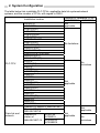
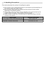
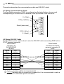
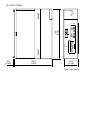
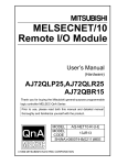
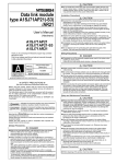
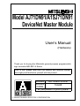
Model AJ71DN91/A1SJ71DN91 DeviceNet Master Module User’s Manual (Hardware) Thank you for buying the Mitsubishi general-purpose programmable logic controller MELSEC-A Series Prior to use, please read both this manual and detailed manual thoroughly and familiarize yourself with the product. MODEL AJ71DN91-U-H-E MODEL 13JL68 CODE IB (NA)-66867-C(0407) MEE 1998 MITSUBISHI ELECTRIC CORPORATION z SAFETY PRECAUTIONS z (Always read before starting use) Before using this product, read this manual and the relevant manuals introduced in this manual carefully and handle the product correctly with full attention to safety. The instructions given this manual are concerned with this product. Refer to the User’s Manual of the CPU module in use for details on the safety instructions for the programmable logic controller system. In this manual, the safety instructions are ranked as "DANGER" and "CAUTION". DANGER Indicates that incorrect handling may cause hazardous conditions, resulting in death or severe injury. CAUTION Indicates that incorrect handling may cause hazardous conditions, resulting in minor or moderate injury or property damage. Depending on circumstances, procedures indicated by CAUTION may also be linked to serious results. In any case, it is important to follow the directions for usage. Store this manual in a safe place so that you can take it out and read it whenever necessary. Always forward it to the end user. [DESIGN PRECAUTIONS] DANGER z If a communications error occurs to a DeviceNetwork, the station in such a communications error will be in a state as follows: (1) The master station (AJ71DN91, A1SJ71DN91) maintains input data which had been received from the slave station before the error occurred. (2) Whether or not the output signal of the slave station to be turned off or maintained is determined by the specification of the slave station or by the parameter settings in the master station. By referring to communications states of the slave station, arrange an interlock circuit in a sequential program and provide safety mechanism externally of the slave station in order the system to operate safely. CAUTION z Do not bundle the control wires and communication cables with the main circuit or power wires, or install them close to each other. They should be installed at least 100 mm (3.94 in.) away from each other. Failure to do so may generate noise that may cause malfunctions. [INSTALLATION PRECAUTIONS] CAUTION z Use the PLC in the operating environment that meets the general specifications given in the user's manual of the CPU module. Using the PLC in any other operating environment may cause an electric shock, fire or malfunction, or may damage or degrade the product. z While pressing the installation lever located at the bottom of module, insert the module fixing tab into the fixing hole in the base unit until it stops. Then, securely mount the module with the fixing hole as a supporting point. If the module is not installed properly, it may cause the module to malfunction, fail or fall off. Secure the module with screws especially when it is used in an environment where constant vibrations or strong impact may be expected. Be sure to tighten the screws using the specified torque. If the screws are loose, it may cause the module to malfunction or fall off. If the screws are tightened excessively, it may damage the screws and/or the module, and cause the module to malfunction or fall off. z Before mounting or dismounting the module, make sure to shut off all phases of the external power supply. Failure to do so may damage the product. z Do not directly touch the conducting parts and electronic parts of the module. This may cause the module to malfunction or fail. [WIRING PRECAUTIONS] DANGER z Make sure to shut off all the phases of the external power supply before starting installation or wiring. Otherwise, the personnel may be subjected to an electric shock or the product to a damage. CAUTION z Always ground the FG terminal for the PLC. There is a risk of malfunction. z Tighten the terminal screws with the specified torque. If the terminal screws are loose, it could result in short circuits or erroneous operation. Tightening the terminal screws too far may cause damages to the screws or the module, resulting in fallout, short circuits, or malfunction. z Make sure that foreign materials such as chips or wire pieces may not be caught inside the module. They could cause a fire, a malfunction, or an operation error. z Make sure to place the communications and power supply cables connected to the module within a duct or clamp them. Unless the cables are placed within a duct or clamped, the module or cables could be broken by swinging or moving of the cables or unintentional pulling to cause an operation error resulting from a contact error. z Do not pull cables by holding them with a hand for removing the communications or power supply cables that are connected to the module. To remove a cable having a connector, hold the connector connected to the module with a hand. To remove a cable not having a connector, loosen the screws fastening to connect the module. The cables being pulled while they are still connected to the module could break the module or cables, or cause an operation error resulting from a contact error. [SETUP AND MAINTENANCE PRECAUTIONS ] CAUTION z Do not touch the terminals while the power is on. Doing so may cause malfunctions. z Make sure to shut off all the phases of the power supply before starting to clean the module or retighten the terminal screws. Otherwise, an operation error could occur. If the screws are loose, it may cause the module to short-circuit, malfunction or fall off. If the screws are tightened excessively, it may damage the screws and cause the module to short circuit, malfunction or fall off. z Do not disassemble or modify the module. Disassembling or modifying the module could cause a failure, an operation error, an injury, or a fire. z Make sure to shut off all the phases of the power supply externally before installing or removing the module. Otherwise, the module could cause a failure or an operation error. z Before handling the module, always touch grounded metal, etc. to discharge static electricity from the human body. Failure to do so can cause the module to fail or malfunction. [DISPOSAL PRECAUTIONS] CAUTION z To dispose of this product, treat it as an industrial waste. About the Manuals The following product are available for this equipment. Refer to the table given below to choose suitable manuals. Detailed Manual Manual name Model AJ71DN91/A1SJ71DN91 DeviceNet Master Module User's Manual Manual No. (Model code) SH-4004 (13JL69) 1. Introduction This manual describes the specifications and part names of Model AJ71DN91/A1SJ71DN91 DeviceNet Master Module (referred to as AJ71DN91,A1SJ71DN91, or DN91, hereafter) which is used in combination with MELSEC-A/QnA Series PLC CPU. DN91 controls DeviceNet devices as the master station for DeviceNet. For specifications of DeviceNet, see DeviceNet Specifications (Release 2.0) Volumes 1 and 2. DeviceNet is a registered trademark of Open DeviceNet Vendor Association, Inc. 2. System Configuration The table below lists installable PLC CPUs, applicable data link systems/network systems, and the number of CPUs, with regard to DN91. Installation location PLC CPU Data link and network A0J2CPU A0J2HCPU A1SCPU(S1) A1SHCPU A1SJCPU(S3) A1SJHCPU A1SCPUC24-R2 A2SCPU(S1) A2SHCPU(S1) A2USCPU(S1) A2USHCPU-S1 A2ASCPU(S1/S30/S60) Q2ASCPU(S1) Q2ASHCPU(S1) A1CPU A2CPU(S1) A3CPU A1NCPU A2NCPU(S1) A3NCPU A3MCPU A3HCPU A2ACPU(S1) A3ACPU A2UCPU(S1) A3UCPU A4UCPU Q2ACPU(S1) Q3ACPU Q4ACPU Q4ARCPU Remote I/O station of MELSECNET Remote I/O station of MELSECNET/B Remote I/O AJ72LP25 station of AJ72BR15 MELSECNET/10 AJ72QLP25 AJ72QBR15 Number of installable CPUs A1SJ71DN91 AJ71DN91 Not applicable No limitations No limitations Not applicable Not applicable Not applicable No limitations 3. Specifications 3.1 Performance specifications The table below lists the performance specifications of DN91.The table below lists the performance specifications of DN91. Item Node type Station numbers which can be set Number of connections which can be generated Specifications Group 2 dedicated client 0 to 63 63 connections for I/O communications 63 connections for message communications Rate of communications data Communications specifications Transmitting I/O communications Receiving 2048 points (256 bytes) *2 Transmitting Message communications Receiving 240 bytes Communications speed Maximum cable length *1 Number of input/output occupied points Internal current consumption (5V DC)(A) Mass(kg) 2048 points (256 bytes) *2 240 bytes One speed can be selected from 125kbps, 250kbps, and 500kbps. Maximum transmitting Length of distance of trunk line drop line Communications Thick Thick and Thick and speed Cable Thin thin cables Maximum Total s Cables coexist 125 156 500m kbaud m See 250 100m Section 6m 250m 78m kbaud 3.1.1 500 100m 39m kbaud Special 32 points 0.24 A1SJ71DN91: 0.23, AJ71DN91: 0.43 *1: The maximum cable length complies with that in the DeviceNet specification (Release 2.0) Volumes 1 and 2. *2: Up to 255 bytes can be transferred per slave station. 3.1.1 Maximum Transmitting Distance when Thick and Thin Cables Coexist The table below lists both the maximum transmitting distance when thick and thin cables coexist. Maximum transmitting distance of trunk line when thick Communications speed and thin cables coexit 125kbaud Thick cable length+5×Thin cable length 500m 250kbaud Thick cable length+2.5×Thin cable length 250m 500kbaud Thick cable length+Thin cable length 100m 4. Part Names 4.1 Part Names This section describes the part names of DN91. AJ71DN91 AJ71DN91 DeviceNet connector RUN L.RUN MS NS DeviceNet RS-232-C RS-232C connector A1SJ71DN91 DeviceNet connector A1SJ71DN91 RUN L.RUN MS NS DeviceNet RS-232-C RS-232C connector 4.1.1 LED Display and Its Details The table below explains LED display and its details. AJ71DN91 RUN L.RUN MS NS LED name RUN Color Red Details Displaying normal operation Illuminating Not illuminating Flickering L.RUN Red Displaying communic ations state A1SJ71DN91 RUN L.RUN MS NS State of LED MS Green (top) Red (bottom) NS Green (top) Displaying module state Displaying module state Displaying network state Illuminating Not illuminating Flickering (periodically) Flickering (random) Illuminating Flickering Unused Illuminating Flickering Red (bottom) Displaying network state Illuminating In normal operation Module error detected Power not supplied Parameter being loaded Module error detected Parameter being loaded In communications Communications stopped Communications ready Communications parameter error DeviceNet interface in normal operation Parameter error In on-line state and communications possible with slave station In on-line state but communications impossible with slave station Duplicated MAC ID error Bus off error occurred. 5. Handling Precautions This section describes the cautions for handling the module. (1) Do not drop or give a hard physical shock to the enclosure and terminal block of the module as they are made of resin. (2) Do not remove the printed circuit board from the enclosure for the module. Removing it could cause a failure. (3) When wiring, make sure that no foreign materials such as wire pieces may be caught inside the module. Remove them if they are caught. (4) Apply a torque as specified in the table below for tightening fitting or terminal screws for the module. Type of screw A1SJ71DN91 Module mounting screw (M4) DeviceNet Connector screw DeviceNet Connector wire screw Tightening torque range 78 to 118 N y cm 35.3 to 48.0 N y cm 60.8 to 82.3 N y cm 6. Wiring This section describes the communications cable and RS-232C cable. 6.1 Wiring Communications Cable The DeviceNet connector of DN91 is configured as illustrated below, where a seal corresponding to its cable color is adhered to the top surface of the connector. V+ (Red) CAN_H (White) Shield (drain wire) CAN_L (blue) V- (black) 6.2 Wiring RS-232C Cable The illustration below explains how to wire the RS-232C cable connecting DN91 with a PC/AT personal computer. Dsub female Dsub female connector for PC/AT connector for personal computer (9 A(15)D530N15 pins) (9 pins) Signal Pin Pin Signal name number number name 1 1 DCD RD 2 2 RxD SD 3 3 TxD DTR 4 4 DTR SG 5 5 GND 6 6 DSR RS 7 7 RTS CS 8 8 CTS 9 9 RI (1) Applying shielded cables are recommended. (2) indicates that no connection is needed but it is recommended to make a connection to eliminate specific orientation. 7. Outside Dimensions (1) AJ71DN91 AJ71DN91 RUN L.RUN MS NS 250 (9.84) DeviceNet 4.2 (0.17) 106 (4.17) RS-232-C 37.5 (1.48) Unit: mm (inch) (2) A1SJ71DN91 A1SJ71DN91 RUN L.RUN MS NS 130 (5.12) DeviceNet RS-232-C 6.5 (0.26) 93.6 (3.69) 34.5 (1.36) Unit : mm (inch) Warranty Mitsubishi will not be held liable for damage caused by factors found not to be the cause of Mitsubishi; machine damage or lost profits caused by faults in the Mitsubishi products; damage, secondary damage, accident compensation caused by special factors unpredictable by Mitsubishi; damages to products other than Mitsubishi products; and to other duties. For safe use y This product has been manufactured as a general-purpose part for general industries, and has not been designed or manufactured to be incorporated in a device or system used in purposes related to human life. y Before using the product for special purposes such as nuclear power, electric power, aerospace, medicine or passenger movement vehicles, consult with Mitsubishi. y This product has been manufactured under strict quality control. However, when installing the product where major accidents or losses could occur if the product fails, install appropriate backup or failsafe functions in the system. Country/Region Sales office/Tel U.S.A Mitsubishi Electric Automation Inc. 500 Corporate Woods Parkway Vernon Hills, IL 60061 Tel : +1-847-478-2100 Brazil MELCO-TEC Rep. Com.e Assessoria Tecnica Ltda. AV. Paulista 1471, Conj. 308, Sao Paulo City, Sao Paulo State, Brazil Tel : +55-11-283-2423 Germany Mitsubishi Electric Europe B.V. German Branch Gothaer Strasse 8 D-40880 Ratingen, GERMANY Tel : +49-2102-486-0 U.K Mitsubishi Electric Europe B.V. UK Branch Travellers Lane, Hatfield, Herts., AL10 8XB,UK Tel : +44-1707-276100 Italy Mitsubishi Electric Europe B.V. Italian Branch Centro Dir. Colleoni, Pal. Perseo-Ingr.2 Via Paracelso 12, 20041 Agrate B., Milano, Italy Tel : +39-039-6053344 Spain Mitsubishi Electric Europe B.V. Spanish Branch Carretera de Rubi 76-80 08190 - Sant Cugat del Valles, Barcelona, Spain Tel : +34-93-565-3131 France Mitsubishi Electric Europe B.V. French Branch 25 Boulevard des Bouvets, F-92741 Nanterre Cedex, France TEL: +33-1-5568-5568 South Africa Circuit Breaker Industries LTD. Tripswitch Drive, Elandsfontein Gauteng, South Africa Tel : +27-11-928-2000 Country/Region Sales office/Tel Hong Kong Ryoden Automation Ltd. 10th Floor, Manulife Tower, 169 Electric Road, North Point, HongKong Tel : +852-2887-8870 China Ryoden Automation Shanghai Ltd. 3F Block5 Building Automation Instrumentation Plaza 103 Cao Bao Rd. Shanghai 200233 China Tel : +86-21-6475-3228 Taiwan Setsuyo Enterprise Co., Ltd. 6F., No.105 Wu-Kung 3rd.RD, Wu-Ku Hsiang, Taipei Hsine, Taiwan Tel : +886-2-2299-2499 Korea HAN NEUNG TECHNO CO.,LTD. 1F Dong Seo Game Channel Bldg., 660-11, Deungchon-dong Kangsec-ku, Seoul, Korea Tel : +82-2-3660-9552 Singapore Mitsubishi Electric Asia Pte, Ltd. 307 ALEXANDRA ROAD #05-01/02, MITSUBISHI ELECTRIC BUILDING SINGAPORE 159943 Tel : +65-6473-2308 Thailand F. A. Tech Co.,Ltd. 898/28,29,30 S.V.City Building,Office Tower 2,Floor 17-18 Rama 3 Road, Bangkpongpang, Yannawa, Bangkok 10120 Tel : +66-2-682-6522 Indonesia P.T. Autoteknindo SUMBER MAKMUR Jl. Muara Karang Selatan Block A Utara No.1 Kav. No.11 Kawasan Industri/ Pergudangan Jakarta - Utara 14440 Tel : +62-21-663-0833 India Messung Systems Put,Ltd. Electronic Sadan NO:111 Unit No15, M.I.D.C BHOSARI,PUNE-411026 Tel : +91-20-712-2807 Australia Mitsubishi Electric Australia Pty. Ltd. 348 Victoria Road, PostalBag, No 2, Rydalmere, N.S.W 2116, Australia Tel : +61-2-9684-7777 HEAD OFFICE : 1-8-12, OFFICE TOWER Z 14F HARUMI CHUO-KU 104-6212, JAPAN NAGOYA WORKS : 1-14, YADA-MINAMI 5-CHOME, HIGASHI-KU, NAGOYA, JAPAN When exported from Japan, this manual does not require application to the Ministry of Economy, Trade and Industry for service transaction permission. Specifications subject to change without notice. Printed in Japan on recycled paper.