1
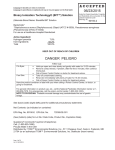
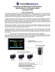
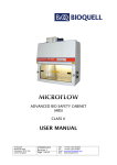
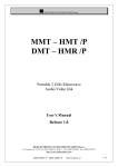
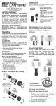
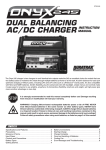
“Walk in”
Modular Material Transfer Chamber
Including Integration of a Bioquell Clarus L2
hydrogen peroxide vapour (HPV) generator
T: +44 (0)1484 354 500
Bradley Junction Ind Est F: +44 (0)1484 354 504
PBSC Ltd
Leeds Road
Huddersfield, HD2 1UR
E: [email protected]
W: www.pbsc.co.uk
Page 1 of 20
Walk in chamber and HPV integrated system - Product
overview.
The Walk in - HPV (Materials Transfer solution) is an integrated through the wall
transfer device for material transfers between different classification rooms where
either an air particulate clean up or material surface bio-decontamination step is
needed before transfer, in either direction.
The Walk in requires a hydrogen peroxide vapour generator attached that can be
connected either room side or in a separate technical area.
Inside view of chamber HPV
Ceiling Mounted Aeration Unit
Air Purge By-pass System (APB)
Stirring Fan (tacho monitoring)
High performance inflatable seal
door
Internal Power Sockets and comms
for Clarus Self Decontamination
Stainless steel bumper rails to
ensure product is 100mm from the
wall for good air flow around the
load.
Overview of integration of the Clarus L2 Hydrogen peroxide
Vapour Generator.
Clarus L2 Hydrogen peroxide vapour Generator used with the Walk-in transfer
chamber must be possible to connect and operate either side of the chamber
(Loading or Unloading side).
Clarus L2 – multi-application H202 Vapour Generator for chambers,
small rooms (up to 75 cu m) and isolators.
T: +44 (0)1484 354 500
Bradley Junction Ind Est F: +44 (0)1484 354 504
PBSC Ltd
Leeds Road
Huddersfield, HD2 1UR
E: [email protected]
W: www.pbsc.co.uk
Page 2 of 20
Overview of HMI integration
•
•
•
•
•
•
The Chamber loading side will carry the master soft touch Siemens HMI
with a slave on the unloading side.
All HMI screens including Clarus L2(1) +Chamber(2) HMI be integrated
into the Chamber master HMI.
At the Master cycle parameters can be changed together with all other
functions.
At the Slave cycles can be selected, run but not modified.
The HMI will replace push button features.
An Emergency override is required in addition to the HMI soft touch screen.
Airflow configuration options – 4 optional configurations will
be required (see walk in chamber system schematic)
1. Recirculation catalyst plus chamber Air Purge Boost system (APB).
2. Recirculation catalyst plus Building HVAC inlet and exhaust.
3. Building HVAC only under control of BMS (signal exchanges required
during HPV cycle).
4. APB only.
Note: Recirculation catalysts to include ceiling mounted aeration unit and the
Bioquell ‘R’ range. Options 3 and 4 have the ability to run a R range aeration
unit.
T: +44 (0)1484 354 500
Bradley Junction Ind Est F: +44 (0)1484 354 504
PBSC Ltd
Leeds Road
Huddersfield, HD2 1UR
E: [email protected]
W: www.pbsc.co.uk
Page 3 of 20
2.0 Process and high level (6log) hydrogen peroxide vapour
(HPV) disinfection requirements overview.
Process and walk in chamber operation overview
The walk in HPV chamber is a transfer device for through the wall material
transfers between different classification rooms.
For GMP applications, transfers can be bi-directional between loading side, GMP
EU Grade D/C and unloading side Grade C/B or the reverse (from the cleaner
production side to the preparation side on the facility).
Interlocking direction/priority is to be selectable. In the case of GMP the priority
is to be from the preparation side (lower classification room) to the production
side (higher classification room), however the decontamination step should be
selectable at the entry or exit side of the chamber.
For BSL/Cat-rooms exit decontamination will be the priority but it will also require
bi-directional decontamination interlocking.
In addition materials can enter and exit from the same side after a disinfection or
air clean up cycle.
The walk in chamber has two principal modes of operation:
1) Air cleanup cycle (Timed particulate clean-up with interlocked doors).
2) Hydrogen peroxide vapour high level disinfection cycle (disinfection of outer
surfaces of materials placed in the walk in chamber for transfer).
The Air clean up cycle provides particulate clean up to EU Grade C/B particle
conditions (as required), via H14 grade inlet HEPA filtration. The particulate clean
up time is a validated time based on clean up from the actual environmental
conditions on the loading or unloading side (as specified).
Walk in chamber doors are required to have an inflatable, interlocked function so
that no two chamber doors are open at the same time. The clean up is
completed after loading before the other side door is provided access for opening.
Each time a chamber door is closed clean up will be completed automatically
before re-entry (door opening) is possible. The chamber HVAC will remain in
operation during standby to maintain room pressure balances.
The hydrogen peroxide vapour high level disinfection cycle
Is an automated cycle for high level disinfection of material outer surfaces,
supported on point contact supports to maximise exposure, before transfer
between rooms.
T: +44 (0)1484 354 500
Bradley Junction Ind Est F: +44 (0)1484 354 504
PBSC Ltd
Leeds Road
Huddersfield, HD2 1UR
E: [email protected]
W: www.pbsc.co.uk
Page 4 of 20
Type of vapour generator used with the walk in chamber.
The hydrogen peroxide vapour generator integrated with the walk in chamber, for
automated disinfection cycles, will be the Bioquell Clarus L2.
When a combined room and chamber function is specified the Clarus L2 and
Chamber PLCs will require communication capability with an interface PLC
controller.
If a Clarus C is required for a larger room suite application combined with a Walk
in Chamber this is a different Chamber product and not covered by this
specification.
T: +44 (0)1484 354 500
Bradley Junction Ind Est F: +44 (0)1484 354 504
PBSC Ltd
Leeds Road
Huddersfield, HD2 1UR
E: [email protected]
W: www.pbsc.co.uk
Page 5 of 20
Overview of walk in chamber – HPV integrated control
systems.
Clarus vapour generators have dedicated siemens S7 PLC programmed for
disinfection cycle control and alarm management of a pre-defined cycle selectable
from stored cycles (up to 99).
The Clarus L2 has an onboard User interface soft touch screen.
The walk in chamber requires a dedicated S7 PLC. Programmed to control and
monitor the chamber configuration and devices. The devices include fans, APB,
valves and pneumatics. The PLC will alarm is the devices are faulty or running
outside of set parameters. Alarms and status functions will be detailed on the
HMI. A HMI will be located beside the load and unload doors.
In addition the walk in chamber temperature will be monitored and is required to
have automatic emergency venting (to cool the chamber/load) in the event of the
maximum temperature alarm limit being reached during the cycle.
The user interface for starting cycles will be via soft touch buttons on the HMI. An
emergency override will be required at each side of the Chamber to abort cycles
in the event of unacceptable deviation. Safe recovery routines will be controlled in
response to alarms or a cycle abort.
An emergency override is required inside the chamber.
The HPV Generator PLC and the walk in chamber PLC are to communicate via a
profibus connection and digital signals.
High level disinfection cycle qualification and control
Outer material surfaces will be decontaminated before transfer via a validated
6log reduction using a hydrogen peroxide vapour sporicidal disinfection cycle.
Each HPV cycle will be developed based on defined load patterns and qualified
with biological indicator challenges of Geobacillus stearothermophilus, highly
resistant spore form inoculation on stainless steel carriers presented in a Tyvek
primary pack.
Gassing cycle development protocols are specified to complement installations at
defined sites.
T: +44 (0)1484 354 500
Bradley Junction Ind Est F: +44 (0)1484 354 504
PBSC Ltd
Leeds Road
Huddersfield, HD2 1UR
E: [email protected]
W: www.pbsc.co.uk
Page 6 of 20
Process and walk in chamber operation overview
The high level disinfection process phases controlled by the Clarus L2 include the
following steps:
1. Conditioning phase: reduction in relative humidity (limited impact
on process in small chambers) and temperature conditioning of the
vapour delivery system.
2. Gassing: to process lethal conditions – achieving saturated vapour
conditions, past dew point, where hydrogen peroxide molecules are
delivered to surfaces (in a micron layer) starting the oxidation
process and free radical release to affect bio-decontamination.
3. Gassing Dwell: contact time of decontamination agent for sporicidal
activity. This phase may include further hydrogen peroxide
injection, if required, otherwise the injected peroxide will maintain
in circulation.
4. Aeration: re-evaporation of micron-layer of decontamination agent
removal of gas residuals for a residue free process. This is a joint
phase with gas residual removal by the vapour generator catalyst
(20-30 cubic metres per hour flow rate) and a recirculation catalyst
device i.e. a ceiling mounted aeration unit (2000 cubic metres per
hour flow rate) or the R range aeration units in conjunction with
the APB (300 cubic metres per hour) or building HVAC. The
chamber exhaust vent system may also include a catalyst filter if
there is a restriction or safety case not to vent peroxide outside.
T: +44 (0)1484 354 500
Bradley Junction Ind Est F: +44 (0)1484 354 504
PBSC Ltd
Leeds Road
Huddersfield, HD2 1UR
E: [email protected]
W: www.pbsc.co.uk
Page 7 of 20
Chamber pressure regulation and maintenance of room to
room pressure differentials, during material transfers.
The APB will be running continuously with flow regulated by a local constant
velocity damper. Interconnection to the chamber exhaust duct may be rigid or
flexible connection (As required). The inlet air fan will have a speed control facility
for adjustment during set up to establish chamber pressure neutral relative to the
defined reference, loading side. During gassing phases the APB will be diverted to
‘By-pass’ via a change over valve system.
Pressure regulation of the chamber through consequential pressure changes, due
to temperature variation through the disinfection process, is maintained by use of
a Catalyst –Hepa pressure balance filter. This filter permits safe pressure release
(via a catalyst/Hepa) or pressure make up via a Hepa filter so that pressure in
the chamber stays neutral with respect to the reference side of the chamber
(typically the lower classification loading side). The pressure balance filter (one
single unit) will have facility of connecting the pressure reference line to either
side of the chamber (specified for the defined application).
There is no automated Leak test required for Walk-in chambers, hence no valve
on the pressure balance filter. However installation and re-qualification leak tests
will be required and for these applications a manual valve is provided to close the
leak path.
T: +44 (0)1484 354 500
Bradley Junction Ind Est F: +44 (0)1484 354 504
PBSC Ltd
Leeds Road
Huddersfield, HD2 1UR
E: [email protected]
W: www.pbsc.co.uk
Page 8 of 20
Leakage management from the chamber
Key safety considerations are that the chamber is always operated at neutral
pressure with respect to the loading side and a very low passive pressure with
respect to the unloading room side. In addition door seals are inflatable with
continuous integrity monitoring required.
Therefore there is very limited motive force for leakage. In the event of
unexpected leakage into either of the much larger volume, adjacent ventilated
rooms it should be possible to support by risk assessment and calculation that the
Operator Exposure Limit (OEL =1ppm) will not be compromised in operation.
Door and valve configurations are to be monitored via positional sensors to
assure HPV gas containment in cycle.
Based on safety considerations together with the fact that hydrogen peroxide
molecules are subject to hydrogen bonding (‘sticky molecules’) hence the vapour
is poor at passive diffusion a pre-gassing leak tests are not used at each cycle run.
Leak testing is completed as an operational qualification at installation and during
routine environmental monitoring programmes.
A qualification leak test cycle is possible via the Clarus L2 controller. The onboard
pressure transducer of the Clarus L2 is used for the leak test control. In this case
the balance Filter sealing plates are fitted and a Leak test only cycle program
used in the Clarus L2, from stored cycles.
T: +44 (0)1484 354 500
Bradley Junction Ind Est F: +44 (0)1484 354 504
PBSC Ltd
Leeds Road
Huddersfield, HD2 1UR
E: [email protected]
W: www.pbsc.co.uk
Page 9 of 20
Walk in Chamber system schematic
Options** Independent AHU:
1. CV / HEPA and extract
fan.
2. CV/HEPA + Catalyst and
extract fan.
Airflow configurations include:
1. Combined recirculation
catalyst, Aeration 2000 +
‘R’ range, and APB
2. Combined recirculation
catalyst plus building
HVAC.
3. Building HVAC only.
4. APB and R range aeration
units
Air supply from
room:
1. Via
chamber
Hepa.
Aeration 2000
1-out
1-in
Walk In Transfer Chamber
Inflatable sealed
and interlocked
doo
s
A Catalyst
unit run output
signal is required from the
Chamber control Tower.
Tower of Power
Gas mixing
Fans (2)
2. Bypass.
2
Pressure
balance
Hepa-Cat
Sensors;
• Temp/RH
•
H2O2
HMI
H2O2 sensor
Material
transfer
Cart
T: +44 (0)1484 354 500
Bradley Junction Ind Est F: +44 (0)1484 354 504
PBSC Ltd
Leeds Road
Huddersfield, HD2 1UR
E: [email protected]
W: www.pbsc.co.uk
Clarus
L2
Vapour
Gen.
Page 10 of 20
Chamber – HPV system functionality and control logic.
HPV Standby - overview
In standby with both transfer doors closed, with the APB unit air into the chamber
is routed from the lower classification loading side through a H14 grade HEPA
filter into the enclosure and around the chamber. Chamber air is then extracted
to the outside via a dedicated air handling unit. Door open availability is indicated
by an illuminated ‘Green’ Door open push button on the soft touch screen. The
chamber status indicator on the soft touch screen is not illuminated in stand by.
HPV Disinfection cycle overview
In HPV mode entry access to the opposite barrier side transfer door is only
possible after successful completion of an automated HPV cycle.
HPV - Disinfection operation will be selected by way of a password protected
setup screen on the user screen.
The required Clarus L2 cycle can be selected from ‘stored cycles’ and advanced on
the Clarus HMI screen to ‘waiting for remote input’.
If both doors are locked and there are no alarms the HPV disinfection cycle can
then be started by pressing the Chamber cycle start push button (the push button
will be illuminated green). Door access will be disabled. The chamber display
indicator will illuminate amber. The inlet air valves and extract valves will close
isolating the chamber for receiving Hydrogen peroxide vapour. The chamber air
inlet fan will remain in operation with air re-routed to extract via the by-pass.
Gas mixing fans inside the chamber will be turned on. Gas mixing fans require
rotation monitoring in operation.
The vapour generator automatically progresses the disinfection cycle through the
conditioning and gassing phases.
Over pressure in the chamber (not expected due to pressure balance HEPA –
Catalyst) will be monitored and if out of specification limits are reached the HPV
cycle will be aborted and emergency aeration started.
Self disinfection of the Clarus L2.
A function is required for self disinfection of the Clarus L2.
As the L2 can be used for other room disinfections the L2 may need transfer into
the clean room or containment room suite. In the case the disinfection cycle is
completed with the L2 inside the chamber with all HPV and control connections
required inside whilst maintaining cycle control from the chamber HMIs.
T: +44 (0)1484 354 500
Bradley Junction Ind Est F: +44 (0)1484 354 504
PBSC Ltd
Leeds Road
Huddersfield, HD2 1UR
E: [email protected]
W: www.pbsc.co.uk
Page 11 of 20
Chamber – HPV system functionality and control logic.
HPV Disinfection cycle overview
At the arrival of the aeration phase there is an operational change to combined
system aeration. Aeration (gas residual removal) is completed by a combination
of the APB or building HVAC. A recalculating aeration unit (Ceiling mounted
aeration unit or the R range aerators) may be used.
At the completion of the timed aeration phase, reaching 1ppm or lower residual
gas concentration, the operator is requested to acknowledge the end of cycle. To
indicate an action is required by the operator the chamber status indicators on
the touch screen flash amber and the cycle end acknowledge illuminates amber.
Transfer Mode –After an HPV Disinfection cycle.
On pressing the cycle end acknowledgement button on the touch screen the
indicator light goes out and the vapour generator unit is automatically switched
off. The chamber status indicator on the touch screen illuminates green and both
door open access indicator lights are illuminated (green). The chamber ventilation
will be running, with the extract route through the chamber.
When a door is requested to be opened the chamber ventilation switches to bypass.
If the unloading door is open there is no possible air exchange between the
loading side and the unloading (GMP)/Production or BSL side.
The unloading side door can be opened and closed as many times as required. If
the loading side door is opened a disinfection cycle must be repeated before the
unloading side door can be opened. The chamber display indicator on the soft
touch screen is to illuminate red if a chamber door is left open for longer than a
preset access time.
T: +44 (0)1484 354 500
Bradley Junction Ind Est F: +44 (0)1484 354 504
PBSC Ltd
Leeds Road
Huddersfield, HD2 1UR
E: [email protected]
W: www.pbsc.co.uk
Page 12 of 20
Monitoring and HPV cycle deviation control.
HPV cycle – critical parameter/ condition monitoring.
The chamber PLC controller is required to control and monitor all associated
devices including, fans, valves, door interlocks, seal inflation and sensors
including hydrogen peroxide vapour gas concentration, flow and temperature.
The vapour generator PLC controls and monitors all critical control points of the
disinfection cycle including monitoring (only) chamber pressure within set limits.
If any critical parameter or condition reaches alarm limits or settings during the
HPV cycle then the cycle will automatically abort (generator goes to Off mode).
At HPV cycle abort the chamber will be required to indicate alarm status.
Depending at what point in the HPV cycle abort occurred the chamber status
must be controlled for safe recovery to either hydrogen peroxide vapour
clearance or a restart of a HPV cycle with successful completion.
HPV cycle abort (generator goes to Off mode) control responses:
1. Cycle abort once cycle started at Conditioning phase:
•
•
Chamber remains in set configuration with both doors locked and in
alarm indication.
To clear the cycle either a cycle end signal is provided by completing a
valid Aeration only or HPV cycle selected from the HPV generator and
re-run or by emergency aeration via the chamber HVAC (selected from
the chamber HMI).
A chamber emergency aeration function will be available for selection at the
chamber. Emergency aeration, via the chamber extract air handling unit (only),
is direct venting of HPV to the outside environment for dilution and natural
breakdown to water and oxygen). The emergency aeration time is validated and
pre-set as a default value.
Alarm messages relating to the HPV generator will be printed with time/date on
the vapour generator printer. During operation event messages will also be
required to be displayed on the vapour generator HMI.
Alarm messages relating to the chamber devices position, On-Off status and
conditions of flow and temperature will require display on the chamber HMI.
There will be no print out of chamber alarm events.
Refer to independent data logging option for temperature and Hydrogen peroxide
vapour gas concentration via Yokagawa data logger.
T: +44 (0)1484 354 500
Bradley Junction Ind Est F: +44 (0)1484 354 504
PBSC Ltd
Leeds Road
Huddersfield, HD2 1UR
E: [email protected]
W: www.pbsc.co.uk
Page 13 of 20
HPV cycle abort by emergency override.
Operators can abort a HPV disinfection cycle by actuation of an emergency
override button (one each side of the Chamber) or by activation of the abort
button on the Clarus L2 HMI.
Room HPV environmental monitor interface.
ATI room monitors (monitoring for leakage at 1ppm) can be interfaced with the
vapour generator via a BMS (building management system). If activated this will
abort the HPV disinfection cycle.
Cycle End following Emergency Aeration
Following emergency aeration the operator will be prompted to take a gas
concentration sample at a sample port provided on the chamber (sample taken
with an independent hand held gas sensor instrument / device suitable for low
level gas concentration measurement e.g. Portasens or drager peroxide tubes).
Following confirmation the chamber concentration is at or below the operator
exposure limit of 1ppm (one part per million for a time weighted average of 8
hours) then acknowledging cycle end (via push button – Green light) will advance
the chamber status to open door access of the loading side only.
Maintenance / repair may be needed before continued use.
Chamber fault conditions and recovery.
Gas mixing fans in the chamber have taco monitoring with failure an alarm
condition that will abort the HPV cycle. Maintenance / repair may be needed
before continued use.
Any flow fault of the chamber aeration support systems, Aeraflow or HVAC
extract, will be alarmed via flow failure as the vapour generator aeration phase
time will not be valid. In this event the vapour generator HPV cycle will be
aborted with the vapour generator advancing to Off mode.
Maintenance / repair may be needed before continued use.
T: +44 (0)1484 354 500
Bradley Junction Ind Est F: +44 (0)1484 354 504
PBSC Ltd
Leeds Road
Huddersfield, HD2 1UR
E: [email protected]
W: www.pbsc.co.uk
Page 14 of 20
HPV cycle print record.
At each cycle phase transition, key control parameters will be printed on the
Clarus L2 printer. Refer to the Clarus L2 User manual.
As standard the hydrogen peroxide gas concentration in the chamber will be
measured and recorded on the Vapour Generator cycle print-out. Gas
concentrations will be printed at phase transitions of:
•
•
•
•
•
•
•
•
•
Cycle start at Conditioning phase
Start of Gassing phase
Peak concentration in Gassing phase.
Start of Gassing Dwell phase.
Peak concentration in Gassing Dwell phase.
Start of Aeration Phase.
Peak concentration in Aeration phase.
At Aeration completion.
At cycle end acknowledgement.
Clarus L2 location and print records.
The Clarus L2 must to be possible to install and operate from a remote location
from the chamber (within specified restrictions).
A remote printer option is not required. All print records will be generated at the
Clarus L2.
It is likely to maintain control of the critical print records the Clarus L2 will not be
installed in an uncontrolled technical area (plant room) but will be installed in the
locality of the chamber.
Chamber – HPV cycle temperature monitoring and control logic for out of
specification deviations.
Temperature monitoring
The vapour generator has temperatures that are controlled monitored and
alarmed in the event of deviation during the HPV cycle. Temperature control and
monitoring includes the vaporiser, refrigeration dryer and re-heater temperatures
and if outside set limits the HPV cycle will be aborted.
The chamber is fitted with a temperature sensor with default set point at 30
degrees C. At arrival of the Max temperature set point during the HPV
disinfection cycle the chamber PLC will monitor this condition for a set length of
time (0 to set hold time).
In the event of the maximum temperature (or above) maintaining for the set
time this becomes an alarm condition with an automatic abort of the vapour
disinfection cycle and start up of Emergency Aeration. The chamber APB will be
automatically changed from by-pass mode to aeration mode to reduce the
chamber temperature. The vapour generator will be aborted to Off mode.
Chamber pressure monitoring in the HPV cycle.
T: +44 (0)1484 354 500
Bradley Junction Ind Est F: +44 (0)1484 354 504
PBSC Ltd
Leeds Road
Huddersfield, HD2 1UR
E: [email protected]
W: www.pbsc.co.uk
Page 15 of 20
The vapour generator has a pressure sensor transducer and will monitor and
record chamber pressures through the HPV cycle. In the event of low or high
pressure alarms (not expected) the disinfection cycle will automatically abort.
Auxiliary power supplies inside the chamber.
During the HPV cycle process equipment may be part of the decontamination load.
In this case the process equipment may require power supplies (single phase) to
run internal fan or ventilation systems to assure full decontamination. Auxiliary
power supplies are required from the Chamber control tower.
T: +44 (0)1484 354 500
Bradley Junction Ind Est F: +44 (0)1484 354 504
PBSC Ltd
Leeds Road
Huddersfield, HD2 1UR
E: [email protected]
W: www.pbsc.co.uk
Page 16 of 20
Optional independent temperature data logging.
The standard chamber system will include a facility for independent data logging
of the chamber temperature with a 2-10 volt output signal for the purpose of
independent data logging on a client supply data logger.
Optional independent hydrogen peroxide vapour gas concentration data
logging.
The standard chamber system will include a facility for independent data logging
of the chamber hydrogen peroxide vapour gas concentration with a 2-10 volt
output signal for the purpose of independent data logging on a client supply data
logger.
Recommended independent Data logger.
Data loggers are not included as part of the chamber package but a ‘Paperless’
Yokohama DX100P is recommended.
BMS pressure monitoring port
In some cases pressure differential monitoring of the Chamber in respect to
adjacent rooms will be required. Such monitoring will be the function of the BMS
and not included in the chamber control system. A pressure connection port is
required in the chamber design in preparation for monitoring via the BMS, if
specified.
Air Clean cycle overview
The Clean air cycle is a dedicated Air particulate clean up cycle only. Chamber
doors are interlocked to ensure the opposite side barrier door can not be opened
until a valid air clean up cycle is completed (expected to be just a few minutes –
specific times validated and set at time of installation).
Air Clean mode operation will be selected by way of a password protected setup
screen on the user screen.
On closure of the selected door the validated air clean up Air purge will be
automatically completed before permitting further opening access to either door.
When a door is requested to be opened the chamber ventilation switches to bypass.
The Chamber Display indicator is to illuminate Red if a chamber door is left open
for longer than a preset access time.
T: +44 (0)1484 354 500
Bradley Junction Ind Est F: +44 (0)1484 354 504
PBSC Ltd
Leeds Road
Huddersfield, HD2 1UR
E: [email protected]
W: www.pbsc.co.uk
Page 17 of 20
Signal exchange summary table of signals between chamber
PLC and vapour generator PLC.
Digital Input and Output to Isolator PLC – Digital Signal exchanges
Mode
Phase
Disinfection
Mode
selection
cycle start,
progressing
to:
Conditioning
phase.
Gassing
phase start
and Run
Aeration
phase
Aeration
complete
and cycle
complete
acknowledge
Cycle End:
Clean door
access
provided
Walk in - Chamber PLC
Vapour Generator PLC
On disinfection selection,
configuration verification the
Disinfection mode is set and a
Disinfection Start signal is
provided to Vapour Generator.
1.
Vapour Generator prepared for
disinfection and cycle status
advanced at Vapour Generator
UMI to ‘Waiting for remote input’
On receipt of Start disinfection
signal the Disinfection cycle
advances to the first stage of
Conditioning of Temperature
and Relative humidity.
Following completion of
Conditioning phase the Vapour
Generator automatically
advances in Gassing phase.
At arrival of Gassing phase the
Vapour Generator provides a
Gassing signal to the Walk in
PLC.
At Gassing signal from Vapour
Generator the GAS PRESENT
display on the Walk in
interface panel is illuminated Amber.
On receipt of Aeration signal
the Air make up and exhaust
valves, V1/V3 are opened with
supply / exhaust fans switched
on followed the bypass valve
V2 closed.
2.
At arrival of Aeration phase
Vapour Generator provides
Aeration signal to Walk in PLC.
3
On receipt of cycle complete
signal Walk in PLC verifies
exhaust flow status as alarm
free and requests for operator
acknowledgement of cycle end.
Following the cycle end
acknowledgement key
operation a Cycle end signal is
provided to the Vapour
Generator.
5
At cycle complete (time
controlled by Vapour Generator
PLC) signal provided to Walk in
PLC to acknowledge cycle End.
4
On receipt of cycle end signal
Vapour Gen goes to Off mode.
After minimum of (10) seconds
remove Disinfection Start
signal
6
Vapour Generator proceeds to
Off mode waiting for further HPV
cycles (as required).
T: +44 (0)1484 354 500
Bradley Junction Ind Est F: +44 (0)1484 354 504
PBSC Ltd
Leeds Road
Huddersfield, HD2 1UR
E: [email protected]
W: www.pbsc.co.uk
Page 18 of 20
Material Airlock (MAL) to HVAC interfacing.
‘Start disinfection (in cycle)’ signal - Output from chamber
‘Alarm Signal’ – Output from chamber
‘Ready for disinfection’ signal – Output from HVAC
‘Start Aeration’ signal – Output from chamber
Note: All signals are volt-free contacts.
In cycle logic will be as follows:
Mal signals ready to ‘Start disinfection’ and waits for ‘Ready for
disinfection’ signal from HVAC.
On Receipt of the ‘Ready for disinfection’ signal the VHP Generator will
transition through its cycle.
When the Aeration phase of the cycle is reached the Mal signals ‘Start
Aeration’ to the HVAC. On completion of the Aeration phase the ‘Start
Aeration’ signal is reset.
When the VHP cycle completes the ‘Start disinfection’ signal is reset.
Reset the ‘Ready for disinfection’ signal.
Alarm Logic will be follows.
HVAC:
MAL
Loss of ‘Start disinfection (in cycle)’ signal and ‘Start Aeration’ signal not
received.
Loss of ‘Start disinfection (in cycle)’ signal less than 2 seconds after the
‘Start Aeration’ signal is reset.
Timeout waiting for ‘Start Aeration’ signal.
An alarm signal will be sent to the building HVAC in an event of a chamber
or vapour generator critical alarm.
Loss of ‘Ready for disinfection’ signal and cycle not complete.
Timeout waiting for ‘Ready for disinfection’ signal.
T: +44 (0)1484 354 500
Bradley Junction Ind Est F: +44 (0)1484 354 504
PBSC Ltd
Leeds Road
Huddersfield, HD2 1UR
E: [email protected]
W: www.pbsc.co.uk
Page 19 of 20
Related Documentation either PBSC or BIOQUELL document formats (as
stated).
Specifications.
1. Walk in FRS / Functional requirement specification – This document.
2. Walk in product specification – hardware – PBSC document.
Factory testing documents
1. SAT- Site acceptance test – PBSC document
Site testing documents
1. IQOQ Clarus L2 – Bioquell document
2. Chamber Mechanical Build sign off document – PBSC document.
3. Chamber electrical test sign off document – PBSC document.
4. Chamber commissioning document – PBSC document.
5. Gassing cycle PQ - Performance Qualification – Bioquell document.
6. Summary Qualification report – Bioquell document.
Manuals
1. Walk in user manual – PBSC/Bioquell document.
2. Clarus L2 user manuals – Bioquell documents.
T: +44 (0)1484 354 500
Bradley Junction Ind Est F: +44 (0)1484 354 504
PBSC Ltd
Leeds Road
Huddersfield, HD2 1UR
E: [email protected]
W: www.pbsc.co.uk
Page 20 of 20