1
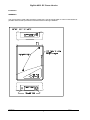
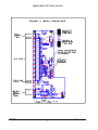
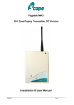
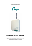
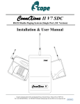
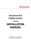
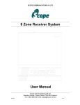
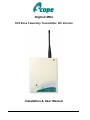
Digilink MK2
10/5 Zone Telemetry Transmitter, DC Version
Installation & User Manual
DLINKMK2DC
Issue 1
Digilink MK2 DC Power Version
PREFACE
Important Installation Information
It is the purchasers’ responsibility to determine the suitability of this equipment and its derivatives for any
given application, Scope cannot give specific advice in this manual, as each use will require independent
evaluation.
Scope has, wherever possible, employed extra safeguards to monitor the system’s performance. Certain
system installations, operational requirements or budgets may, however, limit the effectiveness of these
safeguards. Again, the suitability of the system for any given application must therefore be decided by the
installer and their customer, relative to the application and risk.
Good working practice dictates that a suitable system installation log must be generated, together with a
record of the dates when the system has been manually checked, (with the aid of signal strength meters
etc.) enabling the system performance to be compared with the original installation data.
Scope has no control of the use and application of the frequencies issued by OFCOM. Some equipment
that is licensed may have greater protection than other equipment which is operated on a WT Act License
Exempt basis.
The supply of this equipment is governed by our standard terms and conditions of sale, which can be
found on the reverse of all order acknowledgements*, proforma invoices*, delivery notes, price lists and
invoices. Alternatively, these can be provided on request.
* Faxed proforma invoices and quotations refer to “conditions available upon request”.
Important Safety Information
Scope products are designed to operate safely when installed and used according to general safety
practices. The following requirements should be observed at all times.
Do NOT subject this equipment to:
Mechanical shock
Excessive humidity or moisture
Extremes of temperature
Corrosive liquids
This equipment is designed for indoor use, unless expressly stated otherwise, and must not be used in
classified Hazardous Areas, including areas containing explosive or flammable vapours, unless express
authorisation has been given in writing by the manufacturer. If in doubt, consult your local product dealer
for further information.
Do not obstruct any slots or openings in the product. These are provided for ventilation to ensure reliable
operation of the product and to protect it from overheating.
Only use a damp cloth for cleaning (not liquid or aerosol based cleaners), and ensure that any power is
removed from the unit prior to beginning the cleaning operation.
DLINKMK2DC
Issue 1
2
Digilink MK2 DC Power Version
Preface
Important Safety Information
Removal of covers from the equipment must only be undertaken by authorised service personnel, who
must ensure that power is isolated prior to removal.
Installation
Installation must only be undertaken by an Approved contractor, who shall ensure that all work is carried
out in compliance with IEE Wiring Regulations. For mains powered equipment, a readily accessible
isolating fuse or switched socket must be located within 1 metre of the equipment.
No User Serviceable Parts
Alteration or modification to any part of this equipment, without the prior written consent of the
manufacturer, will invalidate all Approvals and Warranties attaching to the equipment. Further liability for
the operation of the equipment, under the applicable law, will pass to the user, who will absolve the
manufacturer of any further responsibility for it’s correct operation and use.
This product complies with the essential requirements of the R&TTE Directive 1999/5/EC
Copies of the Declaration of Conformity covering this product can be obtained from Scope at:
Quantum House, Steamer Quay, Totnes TQ9 5AL United Kingdom.
Do not discard. At end of life this equipment must be sent to an authorised waste treatment centre.
Contact Scope at the above address for further details.
© Scope Communications UK Ltd, 2011 All Rights Reserved
********************************************************************************
DLINKMK2DC
Issue 1
3
Digilink MK2 DC Power Version
System Overview
The Scope Digilink MK2 DL1012V and DL512V are 12V dc* powered, programmable Short Range Device
(SRD) radio systems which can be used to transmit data to fixed base stations and/or portable receivers.
The unit is supplied with either 5 or 10 inputs, which can be hardware configured to accept either dry
contact (no voltage) or voltage (5-18V dc) triggers. Each input is pre-programmed as either N/O (Normally
Open), N/C (Normally Closed) or C/S (Change of State). Triggering any of the inputs (zones) will result in
pre-programmed data (including up to 80 characters of text message) being transmitted to the selected
receiver or group of receivers.
*24V dc input units also available, model codes DL1024V and DL524V. Consult our Sales team for further details.
The unit can be programmed to repeat transmit (1-5 repeat transmissions or until reset) if required. In
addition, the trigger filter time can be defined between 100 milliseconds and 25 seconds (period for which
the zone must remain in the active state before triggering). One input (IN9) can be configured as a Reset
to clear any current transmission cycles. This can also be used as an “Arm/Disarm” facility for the alarm
inputs. Various other parameters can be programmed to suit specific user requirements.
The Configuration Data sheets accompanying your system will detail how all the various parameters have
been set. It is vital that you retain this information in a safe place as you will need to quote the unit’s serial
number in the unlikely event that you experience any problems. You will also need this information to
order more pagers (these must be matched to the identity of your system).
For advanced users who wish to program the unit themselves, a Programming Kit must be purchased.
This provides a Windows based application running on a PC's USB port, allowing all functions to be
programmed and stored in the system’s secure non-volatile memory. Full details can be found in the
PT10 Pro Configuration Utility provided on CD with the Programming Kit.
Section 1: Installation
The information contained in this Section is intended for authorised system installation engineers
only. Other personnel should not undertake installation of this equipment under any
circumstances.
Siting of the hardware
Before locating the hardware in any given location, it is important to take into account the range of
operation that you require. The standard transmitter can quite easily provide ranges of up to a mile or
more, covering a considerable area with just a quarter wave antenna connected directly to the unit.
For coverage of very large sites, or where exceptionally difficult operating conditions exist, it may be
advantageous to install an external antenna. Installing the transmitter on the second or third floor of a
building will more often than not boost overall range. However, horizontal range is not always required as
much as propagation through a multi-storey building. Here it may be more useful to use a small external
antenna mounted externally at half the building height. Sometimes range is required more in one direction
than in the other: moving the aerial to one side of the building can provide a bias in the required direction,
which may overcome the range difficulties. (See section: Other Antennas).
Important: coaxial feeds which are longer than 5 metres must employ low loss 50 ohm coax. We
normally do not recommend feeds of more than 15 metres for standard applications. If in doubt, contact
our technical department for further advice.
A further consideration is the length and location of the input cables. To avoid interference and possible
false triggering, cable runs should be kept to a minimum (ideally less than 10 metres) and should be
isolated from other cabling (e.g. mains, telecoms. PC networks, etc).
DLINKMK2DC
Issue 1
4
Digilink MK2 DC Power Version
Some major points to consider when installing equipment:
1
Never install antennas near or adjacent to telephone, public address or data
communication lines or overhead power cables.
2
Avoid, where ever possible, running antenna coax alongside other cables.
3
Avoid mounting the transmitter in the immediate vicinity of telephone exchanges or
computer equipment.
4
Always use 50 ohm coaxial cable between the antenna and the transmitter. If cable
runs exceed 5 metres, always use low loss 50 ohm cable such as RG213 or UR67.
Coaxial cable intended for TV, Satellite or CCTV installations is normally 75 OHM and
therefore totally unsuitable for any transmitter installation manufactured by Scope.
5
Also remember that the performance of the system will be affected by the type of
material the unit is mounted on and its surroundings.
The following is a list of materials that this transmitter will be adversely affected by if
mounted on or if mounted in close proximity to:
a)
b)
c)
d)
Foil back plasterboard
Metal mesh or wire reinforced glass
Metal sheeting, large mirrors or suspended ceilings
Lift shafts
All of the above can reflect radio waves and thereby reduce the capability of the
transmitter to perform its desired functions.
6
The circuit boards within this equipment may be harmed by Electrostatic Discharge
(ESD). Installers should ensure that both themselves and the system’s chassis
are grounded before beginning any installation, and should ensure that
adequate anti-static procedures are adhered to at all times.
7
Warning! Never transmit without an aerial attached to the transmitter
8
Warning! Carefully check the Installation section in this manual covering terminal
connections prior to installation. Damage caused by incorrect connection is the
responsibility of the installer!
Installation
The following procedure must be adhered to when installing the Digilink system. Ensure you have taken
into consideration all of the above information before selecting the location for your transmitter. If in
doubt, call our technical helpline on 01803 860710.
1
Remove the cover from the Digilink transmitter unit by slackening the four Pozi head screws
located at the top and bottom of the unit (see Diagram 1).
2
Carefully lift off the cover and set aside.
3
The transmitter should be fixed to an even wall surface using suitable screws fitted through the
three holes provided in the chassis plate. Hold the chassis up to the chosen location and with the
aid of a pencil mark the position of the mounting holes.
DLINKMK2DC
Issue 1
5
Digilink MK2 DC Power Version
Warning: Do not use the chassis plate as a template for drilling the holes into the wall. Hammer drills
vibrating through the chassis may irreparably damage the quartz crystals on the printed circuit boards.
4
Place the Digilink transmitter over the mounting holes and secure the unit with suitable screws.
Check that the chassis plate does not bend and that the screws do not snag or pinch any of the
internal cables.
5
Connect the antenna to the unit via the BNC connector located at the top of the housing. If
the antenna is an external antenna, or an antenna which is separate from the transmitter unit
itself, ensure that the previous criteria covered under the section headed Siting of the
Hardware, have been strictly adhered to (also see section headed Other Antennas).
6
Connect the input cables to the zone terminals. Unless the unit has been specifically configured
for voltage input, these should be simple “dry” (no voltage) contacts only (i.e. isolated switch or
relay contacts).
If configured for voltage input (5-18V dc), the jumper link beside the relevant terminal must be
positioned nearest the “V” symbol marked on the circuit board (see Diagram 2).
If in doubt, check with Scope before proceeding; incorrect connection may cause
permanent damage.
7
For continuous DC power (i.e. derived from mains power), connect the DC power input leads to
the +/– terminals of J1 (Diagram 2). Input Voltage: 12 to 13.8V dc @ 500 mA regulated.
8
For battery-derived DC power systems, connect the DC input leads to the "BATT" connector
CN17. The red Power indicator lead from the front cover of the unit should also be unplugged
from CN2 (PWR LED) and plugged into CN4 (BAT LED). This will flash every 10 seconds to
conserve power, rather than staying on all the time.
9
A relay output is provided to indicate loss of external DC power (only where input power is
connected to J1). If required, connection can be made to J14 terminal block (see Diagram 2),
using either N/O or N/C terminal and the Common terminal. The relay is energised when
external supply is present and drops out when external power is lost. Relay max contact rating
is 1A @ 60V dc and must not be exceeded.
10
Replace the cover and re-tighten the four retaining screws.
11
With power correctly applied, the red Power indicator on the front panel will light (or flash if
configured for battery power) and a "Digilink Reset" message will be sent to the receiver and/or
pager(s) to indicate successful initialisation.
12
The system is now active and will transmit the pre-programmed message for each of the zones
when triggered. Repeat transmissions and other programmed parameters (e.g. battery low
message) will be identified on the Configuration Data sheet(s) supplied with the system. Low
battery voltage is set at 10.5V by default.
DLINKMK2DC
Issue 1
6
Digilink MK2 DC Power Version
Installation
WARNING !
The circuit boards contain static sensitive components. Care should be taken to avoid contact wherever
possible and anti-static precautions should be observed during installation.
DLINKMK2DC
Issue 1
7
Digilink MK2 DC Power Version
DLINKMK2DC
Issue 1
8
Digilink MK2 DC Power Version
Section 2: System Operation
Confirmation of power connection is by way of the red PWR indicator on the front panel.
Confirmation of transmit is by way of the momentary green TX indicator on the front panel.
When any zone is changed to it’s active state, the pre-programmed message for that zone will be
transmitted to the receiver(s). Repeat transmissions can be programmed for added security, these will
be detailed on the Configuration Data sheets provided with your system.
Where the system has been configured for voltage input:
volts present = an open input, no volts = a closed input.
The siren output is an “open collector” type switching to ground. It may be used to switch up to 24V dc
@ 1A max. Note that if it is used to switch a relay, a suitable diode must be connected across the relay
coil (stripe towards positive side of coil).
Problems and Fault Finding.
1
Check that the input cables are connected to the active zones. For a 5 zone unit,
these are the lowermost terminal blocks on the main PCB (see Diagram 2).
2
Check the Configuration Data sheet supplied with the system to confirm the active
(trigger) state of each input i.e. Normally Open, Normally Closed or Change of State.
3
If your system has been configured for Dry Contact operation, ensure that no voltage
is present on the input cables. Also check that cable runs are not excessive
(preferably less than 10 metres) and are not in close proximity to other mains or
telecoms cabling.
4
Check that the receivers are at least 3 metres from the transmitter and aerial.
Under certain conditions it is possible to flood the receivers and corrupt the
data received.
5
Check that any portable receivers have the battery installed with the correct polarity
and are correctly powered up.
6
Check that the red power indicator is lit (or flashing if configured as a battery
powered system). If check the external power supply and input lead.
7
Check that the green TX indicator lights for the duration of the transmission. If not,
go back to the cabling and re-check the terminal connections.
8
Check that the aerial is correctly installed.
DLINKMK2DC
Issue 1
9
Digilink MK2 DC Power Version
Other Antennas
The range and performance of this equipment can be improved by the addition of more efficient
antennas*. These can be installed either inside or outside the building and are connected to the
transmitter with 50 OHM coaxial cable.
The centre fed half wave dipole antenna, measuring approximately 12 inches from tip to tip, will
provide excellent all round local signalling. This can be mounted either inside or outside a building.
Two versions are available:
1) a light duty antenna suitable for sheltered environments/internal installation (LUHFDP).
2) a heavy duty stainless unit with optional mounting hardware for more arduous applications
(UHFDP).
Pre-terminated coaxial feeder cables are available for 5, 10 or 15 metre requirements.
Note ! High frequencies can equate to high power losses. Always use quality cable. RG58 is only
acceptable on cable runs of up to 5 metres. We recommend RG213, or equivalent, on greater lengths.
If in doubt consult your dealer.
*subject to license conditions, specifically, mounting height and Effective Radiated Power (ERP).
Service Information
For all Service enquiries, call (01803) 860740.
Record your system details here for quick reference:Date supplied____/____/____ Serial Number of the base console_________
Transmitter frequency ____Mhz
Number of pagers supplied with the system _______
System base ID number__________
Transmitter baud rate ______________
For information on individual pager types, refer to the appropriate pager manual
DLINKMK2DC
Issue 1
10
Digilink MK2 DC Power Version
System Specification
Input Voltage:
12 to 13.8V dc
System Power Consumption:
less than 300uA (micro Amp) standby, 300mA transmit.
Transmitter:
Power output:
500mW max
Frequency Range:
450-470 MHz
Channel Spacing:
12.5KHz
Adjacent Channel:
better than 200nW @ 4.5 KHz deviation
TX Baud Rate:
512 or 1200
Radio Standards:
ETS EN 300 220
Notified Body No.
0891
EMC Standards:
ETS EN 301 489
General:
Ports:
5 or 10 dry contact/voltage inputs (configurable)
Open Collector (siren) output: 1A max
Relay output for Power Fail indication
USB port for programming function only
Footprint (mm):
184
(L) x 138 (W) x 45 (D) max
excluding aerial
Scope’s policy is one of continuous development and specifications are subject to change without prior notice
DLINKMK2DC
Issue 1
11