1
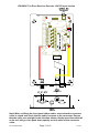
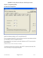
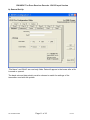
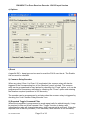
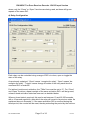
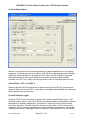
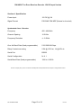
RX10SDC
Ten Zone Receiver Decoder
12V DC Input Version
User Manual
Scope Communications UK Ltd
Quantum House, Totnes, Devon TQ9 5AL England.
Tel: 01803 860700 Email: [email protected]
Ref: RX10SDCUSER
Issue 2
RX10SDC Ten Zone Receiver Decoder 12V DC Input Version
PREFACE
Important Installation Information
It is the purchasers’ responsibility to determine the suitability of this equipment and its
derivatives for any given application, Scope cannot give specific advice in this manual, as
each use will require independent evaluation.
Scope has, wherever possible, employed extra safeguards to monitor the system’s
performance. Certain system installations, operational requirements or budgets may,
however, limit the effectiveness of these safeguards. Again, the suitability of the system for
any given application must therefore be decided by the installer and their customer, relative
to the application and risk.
Good working practice dictates that a suitable system installation log must be generated,
together with a record of the dates when the system has been manually checked, (with the
aid of signal strength meters etc.) enabling the system performance to be compared with the
original installation data.
For UK equipment, Scope has no control of the use and application of the frequencies
issued by OFCOM. Some equipment that is licensed may have greater protection than other
equipment which is operated on a WT Act License Exempt basis.
The supply of this equipment is governed by our standard terms and conditions of sale,
which can be found on the reverse of all order acknowledgements*, proforma invoices*,
delivery notes, price lists and invoices. Alternatively, these can be provided on request.
* Faxed proforma invoices and quotations refer to “conditions available upon request”.
Important Safety Information
Scope products are designed to operate safely when installed and used according to
general safety practices. The following requirements should be observed at all times.
Do NOT subject this equipment to:
Mechanical shock
Excessive humidity or moisture
Extremes of temperature
Corrosive liquids
This equipment is designed for indoor use, unless expressly stated otherwise, and must not
be used in classified Hazardous Areas, including areas containing explosive or flammable
vapours, unless express authorisation has been given in writing by the manufacturer. If in
doubt, consult your local product dealer for further information.
Do not obstruct any slots or openings in the product. These are provided for ventilation to
ensure reliable operation of the product and to protect it from overheating. Only use a damp
cloth for cleaning (not liquid or aerosol based cleaners), and ensure that any power is
removed from the unit prior to beginning the cleaning operation.
Removal of covers from the equipment must only be undertaken by authorised service
personnel, who must ensure that power is isolated prior to removal.
Ref: RX10SDCUSER
Page 2 of 16
Issue 2
RX10SDC Ten Zone Receiver Decoder 12V DC Input Version
Installation
Installation must only be undertaken by an Approved contractor, who shall ensure that all
work is carried out in compliance with National Wiring Regulations. For mains powered
equipment, a readily accessible isolating fuse or switched socket must be located within 1
metre of the equipment.
No User Serviceable Parts
Alteration or modification to any part of this equipment, without the prior written consent of
the manufacturer, will invalidate all Approvals and Warranties attaching to the equipment.
Further liability for the operation of the equipment, under the applicable law, will pass to the
user, who will absolve the manufacturer of any further responsibility for it’s correct operation
and use.
Liability
Scope does not accept liability for any damage or injury, howsoever caused as the result of
misuse of this equipment. It is the responsibility of the user to ensure that the equipment is
operated in the manner for which it was intended and that it is the correct item of equipment
for the required task.
Warranty
This product is warranted as free from defects of workmanship and materials for a period of
one year from the original purchase date. During this time, if there is a defect or malfunction
of this product, Scope will, with proof of purchase, repair or replace at it’s discretion any
defective parts, free of charge. This does not include where the adjustments, parts and
repair are necessary due to circumstances beyond the control of Scope, including but not
limited to fire or other casualty, accident, neglect, abuse, abnormal use or battery leakage
damage.
WARNING ! No User Serviceable Parts
Celui-ci ne contient aucune piece pouvant etre reparee par l’utilisateur
Alteration or modification to any part of this equipment, without the prior written consent of the
manufacturer, will invalidate all manufacturer approvals and warranties. No adjustments can be
undertaken except by qualified and licensed persons as authorised by Scope.
This product complies with the essential requirements of the R&TTE Directive 1999/5/EC.
Copies of the Declaration of Conformity covering this product can be obtained from Scope at:
Quantum House, Steamer Quay, Totnes TQ9 5AL United Kingdom.
Do not discard. At end of life this equipment must be sent to an authorised waste treatment centre.
Contact Scope at the above address for further details.
© Scope Communications UK Ltd, 2005 All Rights Reserved
Ref: RX10SDCUSER
Page 3 of 16
Issue 2
RX10SDC Ten Zone Receiver Decoder 12V DC Input Version
Overview
The RX10SDC is a 12V DC powered POCSAG receiver decoder equipped with 10
individually switchable relays, a Common relay and an RS232 serial port.
A full function PC programming utility allows each relay to be configured to respond
to a transmitted RIC (receiver identity code) or a range of RIC’s. This will allow the
user to independently energise (Close), de-energise (Open) or alternate (Toggle)
the state of each relay by transmitting specified RIC’s or ranges of RIC’s*.
Additionally, the user can Close or Toggle each relay for a defined time period (1065,350 seconds). Sending repeat transmissions during the set time period will reset
the timer, which allows a relay to be used as an “in service” monitor, i.e. so long as
the unit keeps seeing the repeat transmissions within the set time period, the relay
will remain latched. If a transmission fails to be received within the set window, the
relay will drop out at the end of the set time period.
All relays have N/O, N/C and Common connections available on screw terminal
blocks located on the main circuit board (see diagram 1). The maximum contact
rating of each relay is 0.5A @ 125V ac, 1A @ 60V dc.
A Common relay can be programmed to latch when any of the 10 zone relays is
triggered. This can also be programmed to activate an internal sounder.
The unit can be reset by using either the key operated switch on the end panel of
the RX10SDC, or by transmitting a programmed RIC. This will de-energise all relays
and return the system to its initial power up state.
An RS232 serial port provides a data logging or repeater function. This can be
programmed to send transmitted messages to the serial port when either two
individual RIC’s are specified, or when a range of RIC’s is specified. Additionally, the
unit can be configured to send Scope protocol for onward transmission (using a
Scope transmitter on a different frequency).
Front panel LED’s indicate when each relay is energised and a flashing LED advises
when transmitted data is received. A ten LED signal strength indicator is also
provided and a cool blue power LED completes the picture.
Power input requirement is 12V DC @ 2A via the inlet provided.
* Each RIC must be a seven digit number in the range 0000008-2097151, excluding ranges
2007664-2007671 and 2045056-2045063.
Ref: RX10SDCUSER
Page 4 of 16
Issue 2
RX10SDC Ten Zone Receiver Decoder 12V DC Input Version
Section 1: Installation
Certain precautions in siting of the unit apply. As with all radio equipment, attention
must be given to the aerial selected and where the unit is mounted in relation to the
transmitter being monitored. If the unit is to be used with a second transmitter, it
should be sited as centrally as possible within the secondary area to be covered,
although it must of course, be within adequate distance of the originating transmitter.
It is therefore essential that adequate signal reception is checked before fitting the
unit in the desired location. Using the front panel ten LED signal strength array, a
signal strength of 5 or greater is deemed to be sufficient to provide a reliable
consistent link. Readings below this level may lead to poor reception in adverse
atmospheric conditions.
Ranges of up to 1 mile can be achieved quite easily except where the conditions are
such that signal paths are severely obstructed due to reflections or physical
obstacles placed in the way. Such conditions may be experienced where there are
a large number of metallic structures around the site, or where the receiver is sited
in a hollow, i.e. below the level of the transmitter or it’s aerial.
To mount the unit on the wall, slacken the two screws at each end of the case and
separate the cover from the baseplate, taking care not to stress the ribbon cable
which connects the front panel indicators to the main circuit board.
For ease of installation, the ribbon cable can be removed from the main board by
lifting the collar either side of the connector (see diagram 1). This will release the
locking mechanism and the cable can be withdrawn.
The RX10 baseplate should be fixed to an even wall surface using suitable screws
fitted through the 4.75 mm holes provided in the chassis plate. Hold the chassis up
to the chosen location and with the aid of a pencil mark the position of the mounting
holes.
Warning: Do not use the chassis plate as a template for drilling the holes into the
wall. Hammer drills vibrating through the chassis may irreparably damage the quartz
crystals on the printed circuit boards.
Place the baseplate over the mounting holes and fit the fixing screws. Check that
the chassis plate does not bend and that the screws do not snag or pinch any
internal cables.
Connect the antenna to the unit via the BNC connector located at the top of the
housing. If the antenna is an external type, or an antenna which is separate from
the RX10 unit itself, care should be taken to ensure that certain installation criteria
are met, as detailed below.
Ref: RX10SDCUSER
Page 5 of 16
Issue 2
RX10SDC Ten Zone Receiver Decoder 12V DC Input Version
Some major points to consider when installing equipment:
1
Never install antennas near or adjacent to telephone, public address or data
communication lines or overhead power cables.
2
Avoid, where ever possible, running antenna coax alongside other cables and
avoid kinks and coils. Pre-terminated cable should not be altered.
3
Avoid mounting the receiver in the immediate vicinity of telephone exchanges
or computer equipment.
4
Always use 50 ohm coaxial cable between the antenna and the receiver. If
cable runs exceed 5 metres, always use low loss 50 ohm cable such as
RG213 or UR67 to a maximum of 15 metres.
Coaxial cable intended for TV, Satellite or CCTV installations is normally
75 OHM and therefore totally unsuitable for any receiver installation
manufactured by Scope.
5
Also remember that the performance of the system will be affected by the
type of material the unit is mounted on and its surroundings.
The following is a list of materials that this receiver will be adversely affected
by if mounted on or if mounted in close proximity to:
a)
b)
c)
d)
Foil back plasterboard
Metal mesh or wire reinforced glass
Metal sheeting, large mirrors or suspended ceilings
Lift shafts
All of the above can reflect radio waves and thereby reduce the capability of
the receiver to perform its desired functions.
6
The circuit boards within this equipment may be harmed by Electrostatic
Discharge (ESD). Installers should ensure that both themselves and the
system’s chassis are grounded before beginning any installation, and should
ensure that adequate anti-static procedures are adhered to at all times.
Fit the required switch cables to the appropriate relays. These are labelled Zone 1 to
Zone 10 and Common (the Common relay operates when any zone is triggered).
Terminals are available on each relay for Normally Open, Normally closed and
Common.
Finally, refit the cover and connect the DC supply.
To program and configure the unit, the 9 way D connector must be connected to a
COM port on a PC using a standard 9 way serial cable (see Section 3, Programming
Utility). This port can also be used to connect the unit to a serial printer or PC for
data logging purposes, or to a Scope transmitter for repeater application.
Ref: RX10SDCUSER
Page 6 of 16
Issue 2
+
-
RX10SDC Ten Zone Receiver Decoder 12V DC Input Version
Note! When re-fitting the front panel ribbon cable, ensure that the connector
collar is raised and check that the cable is square to the connector. Ensure
that the cable runs straight in the direction shown. Gently insert the cable tail
as far as it will go, then push down equally on both sides of the connector
collar.
Ref: RX10SDCUSER
Page 7 of 16
Issue 2
RX10SDC Ten Zone Receiver Decoder 12V DC Input Version
Section 2: System Operation
The RX10 can be used to remotely switch up to 10 different circuits. This can be
achieved by independently programming each zone with simple Close and Open
latching commands. Zones can also be programmed for momentary operation, and
if required, a single command can be used to toggle the state of each zone. A Reset
function returns all zones to their initial state. This can be activated either over the
air (by transmitting the programmed command) or by operation of the front panel
keyswitch. A Common relay will latch when any zone is active. This can also be
programmed to operate an internal sounder. The relay can be used for connection
to an external sounder or light, providing a remote indication of system activity.
Both the configuration and uses of the RX10 are limited only by the user’s
imagination, so here we will provide just a few examples of how it’s functionality can
be utilised.
Example 1: you want to use Zone 1 to switch on a light when you transmit a
command. You then want to switch the light off by transmitting a different command.
To do this, connect your switch wires to the N/O and Common terminals of Zone 1.
In the RX10 Pro Configuration utility, click on the Chan 1 tab. In the “Close” section,
enable the tick box then enter the chosen RIC (or range of RIC’s) for switching the
light on. In the “Open” section, enable the tick box and enter your chosen RIC (or
range of RIC’s) for switching the light off (for a fuller explanation of programming the
RX10, see Section 3).
When you transmit the “Close” RIC stored in Chan 1, the relay contacts will close,
completing the circuit. The Zone 1 LED on the main board and on the front panel will
light. The Common relay will also operate and the Common LED on the main board
and front panel will also light. When you transmit the “Open” RIC stored for Zone 1,
the relay contacts will open, breaking the circuit. The Zone 1 LED’s will extinguish,
the Common relay contacts will open and the Common LED’s will extinguish.
Example 2: you want to use a single command on Zone 3 to switch a motor both On
and Off for a 10 second period. To do this, connect your switch wires as in Example
1 if you require the motor to be in the Off state when the RX10 is initially powered up
or reset. If you require it to be ON in this state, connect the wires to the N/C and
Common terminals. In the RX10 Pro Configuration utility, click on the Zone 3 tab,
then set the “Tmax” value to 10 (seconds). Now enter your command RIC (or range
of RIC’s) in the “Toggle” section and enable the tick box.
When you transmit the stored “Toggle” RIC, the motor will run for 10 seconds, then
stop. Transmit again to run the motor for a further 10 seconds. If you transmit the
RIC whilst the motor is running (i.e. during the set time period of 10 seconds), it will
stop. Transmit again to run the motor for a further 10 second period.
Example 3: you have a “supervised” system where the transmitter sends out test
calls at timed intervals. If the receiver fails to receive any test calls, you want to
signal this by opening a pair of contacts.
To do this, in the RX10 Pro Configuration utility choose a zone (Chan) and set the
Tmax value to a period greater than your transmitter’s test call period. Enable the
“Close” function and enter your test call RIC. Wire the signal cables to the N/O and
Common terminals of the selected Zone.
Ref: RX10SDCUSER
Page 8 of 16
Issue 2
RX10SDC Ten Zone Receiver Decoder 12V DC Input Version
Note that the relay contacts will be open until the first test call is received, when they
will close for the set time. Because the test call interval is shorter than the set time,
the timer is reset with every successfully received call, so the relay contacts remain
closed until a call is missed, when they will open until a call is successfully received.
Because both N/O and N/C terminals are available for each relay, this can cause
confusion when deciding on whether to select the “Close” and “Open” functions. To
avoid confusion, the “Close” function for each relay can be best described as “when
the relay is energised”, and the “Open” function as “when the relay is de-energised”.
For example, if the N/C terminal configuration is used, when the “Close” command
RIC is transmitted, the relay will energise and the contacts will go open. After this, if
the “Open” command RIC is sent, the relay will de-energise and the contacts will
close. Similarly, if the N/O terminal configuration is used, when the “Close”
command RIC is transmitted, the relay will energise and the contacts will close. After
this, if the “Open” command RIC is sent, the relay will de-energise and the contacts
will open.
Ref: RX10SDCUSER
Page 9 of 16
Issue 2
RX10SDC Ten Zone Receiver Decoder 12V DC Input Version
Section 3: Programming Utility
a) Comm Port Configuration
Install the software provided on a PC running Windows XP.
Prior to programming the RX10, enter the Com port and the comms baud rate which
you are using on your PC to program the RX10.
Fit a standard 9 pin “null modem” serial cable* between your PC Com port and the
RX10 serial port.
[*available from Scope, contact our sales dept. for full details]
To check the set baud rate of the RX10, select “GET” to read the stored data. The
unit is now ready to accept programming data.
Ref: RX10SDCUSER
Page 10 of 16
Issue 2
RX10SDC Ten Zone Receiver Decoder 12V DC Input Version
b) General Set Up
“File Name” and “Build” are read only fields. Data will appear in the boxes after a file
is saved or opened.
The baud rate and data polarity must be chosen to match the settings of the
transmitter used with the system.
Ref: RX10SDCUSER
Page 11 of 16
Issue 2
RX10SDC Ten Zone Receiver Decoder 12V DC Input Version
c) Options
i) Reset
A specific RIC + beep type can be used to reset the RX10 over the air. The Enable
tick box must be checked.
ii) Common Relay/Sounder
When any relay (Chan 1 to Chan 10) is activated, the common relay will also be
triggered if the corresponding box in the “Monitors” panel is ticked. The common
relay can be programmed to stay latched by checking the “Fixed” option, or it can be
programmed for momentary activation by checking the “Timed” option and entering
the duration required (maximum is 255 seconds).
The sounder can be programmed to activate when the common relay is triggered by
checking the “Link Common Relay/Sounder” box.
iii) Repeated Toggle Command Filter
Where the transmitter is programmed to send repeat calls for added integrity, it may
be required to filter out these repeats if the “Toggle” function is being used
(otherwise the relay will change state every time a repeat call is received). Enter the
required time in the box provided (1-255 seconds). Note that this is not necessary
Ref: RX10SDCUSER
Page 12 of 16
Issue 2
RX10SDC Ten Zone Receiver Decoder 12V DC Input Version
where only the “Close” or “Open” functions are being used, as these will ignore
repeats of the same RIC.
d) Relay Configuration
Each relay can be controlled using a range of RIC’s to close, open or toggle the
state of the relay.
As previously explained, “Close” means “energise the relay”, “Open” means “deenergise the relay”. “Toggle” means change the state of the relay each time the
command RIC is received.
For latched (continuous) activation, the “TMax” box must be set to “0”. For “Close”
and “Open” functions, repeat receipts of the same activation RIC’s will be ignored,
unless a timed activation state has been set, as detailed below.
Where a timed state is required, this can be set between 10 and 65,350 seconds,
with a 10 second resolution, after which the relay will revert to its previous state. As
explained above in Example 3, if the same activation RIC is received during the
timed period, the counter will be reset, thereby extending the period by the set time.
Ref: RX10SDCUSER
Page 13 of 16
Issue 2
RX10SDC Ten Zone Receiver Decoder 12V DC Input Version
e) Serial Data Output
Where it is required to send message data for onward transmission or for logging
purposes, the serial port can be enabled. The RX10 can be programmed to accept
either two individual RIC’s or a range of RIC’s. Note: the RX10 does not provide
time/date stamping, although this function could be facilitated using suitable
software on a PC, or by using a POS style printer with an onboard real time clock.
i) Serial Data – RIC 1 and RIC 2
Where individual RIC’s are selected, a specific beep type (A,B,C,D) must also be
entered. When the chosen RIC + beep type + message is transmitted, the message
will be passed to the serial port.
ii) Serial Output Logger
A range of RIC’s can be entered, together with either a specific beep type or “All”,
where any beep type is valid. If the serial port is being used to pass data to a Scope
transmitter (a repeater application), the tick box “Scope Protocol Output Format”
should be checked. This will output the Scope control codes + RIC in front of the
message. Where numeric messages are sent for onward transmission, the tick box
“Interpret as numeric messages” must be checked. See Appendix A for full details.
Ref: RX10SDCUSER
Page 14 of 16
Issue 2
RX10SDC Ten Zone Receiver Decoder 12V DC Input Version
Section 4: Specification
Power Input:
12V DC @ 2A
Signal Format
POCSAG FSK NRZ (Normal or Inverted)
Synthesized Class 1 Receiver
Frequency
450 –464 MHz
Channel Spacing
12.5 KHz
Frequency Deviation
+/- 2.5KHz
Over Air Baud Rate (fixed programmable)
512/1200/2400 bps
Relay Contact max rating
0.5A @ 125V ac, 1A @ 60V dc
Serial Port
RS232
Serial Configuration
N, 8, 1
Serial Baud Rate (fixed programmable)
1200 to 115200
E & OE. Scope’s policy is one of continuous development and specifications are subject to change without notice
Ref: RX10SDCUSER
Page 15 of 16
Issue 2
RX10SDC Ten Zone Receiver Decoder 12V DC Input Version
Appendix A
Serial Output Options
(Applicable to: DC, SDC & SAC models)
The serial port on the RX10 outputs alphanumeric and numeric message data1. This data
can be sent onwards to a suitable Scope transmitter, third party device, or data acquisition
software package.
The format of the data is dependent on how the RX10 has been programmed, using the
RX10 Pro Configuration Utility V3.1
There are four selectable options contained within the Serial Data Tab:
a.
b.
c.
d.
Serial Data – Feed to Serial Sign (1)
Serial Data – Feed to Serial Sign (2)
Serial Output – Alpha Messages
Serial Output – Numeric
a & b) The Serial Data – Feed to Sign (1) and (2) options will each accept a single RIC2
with a fixed Beep3 type. This will output the printable ASCII data that is contained within the
received message, along with a <CR> through the serial port.
c) The Serial Output – Alpha messages option will accept a single RIC as above, and also
a range of RICs, together with options for accepting all beep types, or filtering to allow only
a fixed single beep type.
There are also options for prefixing any ASCII data with standard Scope protocol4, and for
substituting any incoming RIC and Beep types with an alternative fixed version before the
printable ASCII data, along with a <CR> is sent through the serial port.
d) The Serial Output – Numeric messages option is the same as above, but for numeric
messages only. You can select both the alpha and numeric Serial Output options together,
but the RIC ranges must not overlap.
Examples
In each of the examples below, the string received from the transmitter is:
A0100008ATEST<CR>.
RX10 Serial Data Option
RX10 serial output (shown in Bold)
Serial Data – Feed to Sign
The Serial Output – Alpha messages
With Scope protocol
With sub address set as 0200800, beep D
TEST <CR>
TEST <CR>
A0100008ATEST<CR>
A0200800DTEST<CR>
1
After receipt of correctly encoded data from a Scope transmitter.
Radio Identity Code, sometimes called a Capcode, ID or address. This is the unique address sent from the
transmitter.
3
Beep types are a suffix to the RIC code. In the Scope protocol they are A, B, C & D. Designed to invoke a
different audible beep pattern in a radio pager, they can also be used as a control character to increase the
number of useable addresses.
4
Scope protocol comprises of a prefix character either A or N (designating alpha or numeric), followed by a 7
digit RIC, then beep type, then message. Sometimes a baud rate character will be inserted between the A or N
and the RIC, this will be N for 512Hz and F for 1200. Examples of these Scope protocol strings would be
A0100000Dtest<CR> and AF0100000Dtest<CR>.
2
Ref: RX10SDCUSER
Page 16 of 16
Issue 2