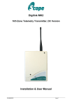
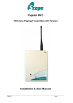
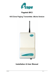
Download PAGETEK PRO MK2 User Manual
Transcript
SCOPE COMMUNICATIONS UK LTD
PAGETEK PRO MK2 USER MANUAL
PAGETEK PRO MK2
Fire & Security Paging System
User Manual
Ref: PTPROMK2USER1
Page 0 of 11
Issue 1
SCOPE COMMUNICATIONS UK LTD
PAGETEK PRO MK2 USER MANUAL
PREFACE
Important Safety Information
Scope products are designed to operate safely when installed and used according to
general safety practices. The following requirements should be observed at all times.
Do NOT subject this equipment to:
Severe Mechanical shock
Excessive humidity or moisture
Extremes of temperature
Corrosive liquids
This equipment is designed for indoor use, unless expressly stated otherwise, and must not
be used in classified Hazardous Areas, including areas containing explosive or flammable
vapours, unless express authorisation has been given in writing by the manufacturer. If in
doubt, consult your local product dealer for further information.
Only use a damp cloth for cleaning (not liquid or aerosol based cleaners), and ensure that
any power is removed from the unit prior to beginning the cleaning operation.
It is important that a system log is maintained and that any faults or alarm conditions are
recorded, together with the date and time of the occurrence and the resulting remedial
activity performed by the authorised maintenance engineer.
A suitable System Event log is contained in Annex A of this booklet. All installation and
scheduled maintenance activities should be recorded in the log, together with any reported
malfunctions or alarm activity.
After installation of the Pagetek Pro system, the purchaser should be given a completed
Design certificate, Installation certificate and Acceptance Certificate by the Installer
Company. It is important that these documents are retained in a safe place for future
reference.
Warning!
Opening of access doors and removal of covers from the equipment must only be
undertaken by authorised service personnel, who should ensure that power is isolated prior
to commencing any maintenance work.
Ref: PTPROMK2USER1
Page 1 of 11
Issue 1
SCOPE COMMUNICATIONS UK LTD
PAGETEK PRO MK2 USER MANUAL
PREFACE
Liability
Scope does not accept liability for any damage or injury, howsoever caused as the result of
misuse of this equipment. It is the responsibility of the user to ensure that the equipment is
operated in the manner for which it was intended and that it is the correct item of
equipment for the required task.
Warranty
This product is warranted as free from defects of workmanship and materials for a period of
one year from the original purchase date. During this time, if there is a defect or
malfunction of this product, Scope will, with proof of purchase, repair or replace at it’s
discretion any defective parts, free of charge. This does not include where the adjustments,
parts and repair are necessary due to circumstances beyond the control of Scope,
including but not limited to fire or other casualty, accident, neglect, abuse, abnormal use or
battery leakage damage.
WARNING ! No User Serviceable Parts
Caution ! Risk of electric shock, do not open.
Alteration or modification to any part of this equipment, without the prior written consent of
the manufacturer, will invalidate all manufacturer approvals and warranties. No
adjustments can be undertaken except by qualified and licensed persons as authorised by
Scope.
This product complies with the essential requirements of the R&TTE Directive 1999/5/EC
Copies of the Declaration of Conformity covering this product can be obtained from Scope at: Quantum
House, Steamer Quay, Totnes TQ9 5AL United Kingdom.
Do not discard. At end of life this equipment must be sent to an authorised waste treatment centre. Contact
Scope at the above address for further details.
© Scope Communications UK Ltd, 2014 All Rights Reserved
Ref: PTPROMK2USER1
Page 2 of 11
Issue 1
SCOPE COMMUNICATIONS UK LTD
PAGETEK PRO MK2 USER MANUAL
1) Pagetek Pro MK2 System Overview
The Pagetek Pro MK2 is an industrial paging system intended for use with professional Fire
and Security systems installed in commercial/industrial premises. The system is primarily
designed to alert the hearing impaired in the event of a fire or other emergency where an
audible sounder is the normal means of indication. Typical users include factories, offices,
universities, schools, hospitals, hotels and public buildings.
The Pagetek Pro MK2 has been designed to comply with the recommendations detailed in
BS 5839-1: 2013, Section 18 and Annex C, for alerting the hearing impaired to the
activation of a fire alarm. The system can also be pre-configured for use with a security
alarm panel to alert guards who might be located remote from the main premises.
A key operated System Test facility is provided for routine confidence checking. When
activated, the display will read “SYSTEM TEST” and this message will also be transmitted
to all pagers. If a Fire input is activated during the test, this will over-ride the Test message
at all times.
Upon activation of any Fire Zone input, the Pagetek Pro MK2 system will enter the fire alert
condition, prioritising and transmitting the Fire message to all pagers. The transmissions
will be repeated until the fire condition is reset using the front panel keyswitch or by autoreset from the fire panel (see section 4). The system can also be used to transmit other
paging messages via an RS232 serial port and/or an optional ethernet port.
Special format Scope pagers ensure that users are alerted by distinct vibrate patterns and
clear text messages. This includes distinct vibrate alerts for emergency messages, a
vibrating out of range indicator which also displays “No Service” on the pager if the radio
link is lost, and a vibrating low battery indicator.
A Sounder Mute button is provided on the front panel to suppress the Pagetek Pro’s
internal sounder during a fault or fire event.
Compliant pagers for use with this system are: GEON8T, GEO N8S, GEO N9S (numeric
with pre-stored text messages), GEO 40A8 and GEO 40A9 (2 line alphanumeric) and GEO
84Z and GEO 85Z (4/8 line alphanumeric). Please contact our Sales team for further details.
Brochures for these pagers are also available for download at www.scope-uk.com
2) Conformity
CE marked and compliant with the R&TTE Directive 1999/5/EC.
Standards applied: EN 300 224 (On-Site Radio Paging), EN 60950 (Safety),
EN 301 489 (EMC) and the additional EMC requirements of BS 5839-1: 2013.
Compliant with BS 5839-1: 2013, para. 18 and Annex C.
Ref: PTPROMK2USER1
Page 3 of 11
Issue 1
SCOPE COMMUNICATIONS UK LTD
PAGETEK PRO MK2 USER MANUAL
3) System Operation
3.1 System Standby
a) The Pagetek Pro MK2 system is instructed directly by your Fire Alarm and is therefore
fully automatic in operation.
b) There is a key-operated function switch on the front panel which provides a system
Reset facility and a System Test function for routine confidence checking (see Sections 4 &
5).
c) The display advises of current system status. A summary of the available messages and
their meaning is detailed in section 3.3 below. Note that all fault messages must be
reported to your system maintenance provider and should be recorded in the System Log
located at the back of this manual (Annex A).
ON
RESET
SYSTEM TEST
d) In normal standby mode, the green mains power light is on, the display states “SYSTEM
HEALTH OK” and the system icon blinks. At regular intervals (default is 50 seconds) the
bottom line of the display briefly states “TX IN SERVICE”, this is the monitoring signal sent
to the pagers for range verification.
e) In the unlikely event that the system icon remains off or frozen on for more than 1
minute, this would indicate a system software malfunction and the maintenance engineer
should be called to check and Reset the system using the front panel keyswitch (see
Section 4).
3.2 Fire Alert Condition
a) In the event of a fire, the host Fire Panel will trigger the Pagetek Pro MK2, which will
transmit repeated Fire messages to all the pagers on the system. The front panel display
will indicate the applicable Fire Zone. This message will also be transmitted to all the
pagers. Once it has entered the Fire Alert mode, the system can only be reset by either the
front
Ref: PTPROMK2USER1
Page 4 of 11
Issue 1
SCOPE COMMUNICATIONS UK LTD
PAGETEK PRO MK2 USER MANUAL
panel keyswitch (see section 4) or a reset command from the fire panel (where system has
been configured for this option).
3.3 Fault Monitoring
a) The Pagetek Pro MK2 monitors its own system health and reports various faults as
shown below. In all cases, the event must be written into the System Log (see Annex A)
and the maintenance engineer called to attend to the problem.
b) Rectification of the fault will clear the fault condition and the display will return to the
standby condition as in Section 3.1 (d) above.
c) All these events will also be notified to the host Fire panel as a “common fault”, and
where an engineering pager has been provided, will be transmitted to that pager wherever
possible. A full description of the fault conditions is contained in Section 8 of the Installation
Manual.
Ref: PTPROMK2USER1
Page 5 of 11
Issue 1
SCOPE COMMUNICATIONS UK LTD
PAGETEK PRO MK2 USER MANUAL
Ref: PTPROMK2USER1
Page 6 of 11
Issue 1
SCOPE COMMUNICATIONS UK LTD
PAGETEK PRO MK2 USER MANUAL
d) All fault conditions will trigger the Pagetek Pro’s internal sounder, which will beep until
the fault condition is rectified, or until the Sounder Mute button on the front panel is
pressed.
4) System Reset
a) After a Fire Alert condition, the system must be *manually reset to cancel the alarm.
This task must only be performed by an authorised person who has received adequate
training in the safe operation of the system.
*[unless the system is auto-reset by the Fire panel using the Reset input]
b) Using the front panel keyswitch, insert the key and turn it anti-clockwise to initiate a
Reset and cancel the Fire Alert condition. This will silence the sounder, extinguish the red
LED and the display will revert to “SYSTEM HEALTH OK”
d) Now turn the key clockwise back to the “ON” position and remove it. Note the activity in
the System Log.
Note: if any Fire input stays active, the system will revert to the Fire Alert condition
after the Reset. Always return the key to the “ON” position before removal.
ON
RESET
SYSTEM TEST
5) System Test
a) To check the functionality of the system and the integrity of the radio link, a key-operated
Test function is provided on the system front panel.
b) Inserting and turning the key a quarter turn clockwise will initiate the Test mode, which
will send one transmission of the message “SYSTEM TEST” to all pagers present on the
system.
Ref: PTPROMK2USER1
Page 7 of 11
Issue 1
SCOPE COMMUNICATIONS UK LTD
PAGETEK PRO MK2 USER MANUAL
c) Whilst in the Test mode, the display will state “SYSTEM TEST” and the yellow fault LED
will be lit. The warning sounder will beep every second as a reminder.
d) If the system receives a valid Fire trigger whilst in Test mode, the Fire signal will override the Test message at all times.
e) Always return the key to the ON position before removal. A spare key is also provided.
ON
RESET
SYSTEM TEST
Note: whilst in Test mode, the “TX IN SERVICE” transmissions to the pagers are
suppressed. If the system is left in the Test mode for more than two minutes, the
pagers will display “NO SERVICE” until the Test mode is disabled (whereupon the In
Service transmissions will resume). This acts as an additional safety feature to
ensure that the Test condition is switched off after use.
6) Sounder Mute Facility
During fault or fire indication, the Pagetek Pro’s internal sounder may be silenced by
pressing the Sounder Mute button on the front panel. If a new fault or fire condition arises,
the sounder will re-activate.
7) Pagers
7.1 In Range Indicator
a) All applicable Scope pagers are equipped with an In Range indicator function, consisting
of an antenna icon on the display, which will extinguish if the pager fails to detect test calls
sent by the Pagetek Pro MK2 within a preset time (default is 4 minutes).
Ref: PTPROMK2USER1
Page 8 of 11
Issue 1
SCOPE COMMUNICATIONS UK LTD
PAGETEK PRO MK2 USER MANUAL
b) When used with the Pagetek Pro MK2 system, an additional text message and tactile
alert feature is pre-programmed into the pager. If the pager fails to receive a test call within
a 4 minute period (test calls are sent every 50 seconds as a default), the pager will display
“NO SERVICE” and vibrate until acknowledged by the user. After acknowledgement, the
“NO SERVICE” message will remain on the pager until it comes back into the service area.
c) If the pager remains outside the coverage area, after 15 minutes it will provide a
vibrating reminder alert (2-3 seconds), repeated every 15 minutes until back in coverage.
d) Note that this function will be enabled for any Scope pagers supplied with or for a
Pagetek Pro system.
7.2 Low Battery Indicator
a) All applicable Scope pagers are equipped with a Low Battery indicator function,
consisting of a part-empty battery icon on the display, which will appear when the battery
needs replacing.
b) When used with the Pagetek Pro MK2, an additional text message and tactile alert
feature is pre-programmed into the pager. This will display “LO CELL” or “LOW BATTERY”
and vibrate (distinct pattern) for 3 seconds, repeated every 15 minutes until the battery is
replaced (or becomes exhausted).
7.3 Vibrate alerts
a) All applicable Scope pagers are equipped with distinct vibrate alerts, so that a LOW
BATTERY or NO SERVICE type call can be differentiated from a FIRE type call. In all
cases, distinct messages are displayed on the pager’s screen. Contact our technical sales
team on 01803 860720 for further details and advice on selecting the most appropriate
pager for your requirements.
Ref: PTPROMK2USER1
Page 9 of 11
Issue 1
SCOPE COMMUNICATIONS UK LTD
PAGETEK PRO MK2 USER MANUAL
System Specification
Mains Input:
90-230V ac @ 50-60 Hz
Mains Power Consumption:
10W max
System Operating Voltage:
14.2V dc
System Power Consumption:
less than 70mA standby, 1.2A transmit.
Transmitter:
Power output:
Not exceeding 2W
Frequency Range:
459.050, 459.100, 459.225, 459.275 MHz
Channel Spacing:
12.5 or 25 KHz
Adjacent Channel:
better than 200nW @ 4.5 KHz deviation
TX Baud Rate:
512 (default) or 1200 baud
Type Approval to:
EN 300 224
Type Approval No.
SYNLINK
Notified Body No:
0891
General:
Ports:
4 x dry contact n/c inputs (3 x Fire, 1 x Fault)
1 x Common Fault n/o relay contact output
COM1: RS232 serial port
Battery Backup Supply:
12V 18Ah sealed lead acid battery (not supplied)
[internal mounting kit, cable assembly and fuse is supplied fitted]
System Conformity:
R&TTE Directive 1999/5/EC.
EN 300 224 (On-Site Radio Paging)
EN 60950 (Safety)
EN 301 489 (EMC)
Additional EMC requirements of BS 5839-1: 2013.
Compliant with BS 5839-1: 2013, para. 18 and Annex C
Footprint:
Wall mounting centres:
(H) 380* x (W) 320 x (D) 110 mm
(H) 344 x (W) 220 mm. Hole Dia. 4.75mm
[*840 mm with 3/4UHF antenna]
Scope’s policy is one of continuous development and specifications are subject to change without prior notice. E & OE.
Ref: PTPROMK2USER1
Page 10 of 11
Issue 1
SCOPE COMMUNICATIONS UK LTD
PAGETEK PRO MK2 USER MANUAL
Annex A
System Event Log
Address of protected premises: …………………………………………………………………....
Responsible person: …………………………………………………………………………………
Installed & commissioned by ……………………………………………………………………….
Maintained under contract by: …………………………………………………..until: ……………
Tel: ……………………………… Normal max. attendance time for a technician: …………….
System battery (type: sealed lead acid 12V 18Ah) replacement period:……………………….
Events other than false alarms or maintenance work
Date
Time
Event (e.g. Test, valid fire alarm, valid
fault signal)
Zone/Location
Date
completed
Action required
(where applicable)
Signed
False Alarms
Date
Time
Zone
Maintenance
Visit
required
Cause
(if known)
Technicians
Report
Signed
Maintenance Work (inc. range tests)
Date
Time
Ref: PTPROMK2USER1
Reason & nature of work
Page 11 of 11
Location
Signal
Strength
Issue 1
Signed


