1
Embedded Control PC
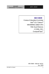
AEC-6820B
AEC-6820B
Fanless Embedded Control PC
VIA Eden 677MHz/ C3 1GHz
CPU With 2 PCMCIA slots,
Ethernet, 2 COMs, Audio,
CompactFlash™
AEC-6820B Manual 1st Ed.
July 2005
AEC-6820B User Manual
1
Embedded Control PC
AEC-6820B
Copyright Notice
This document is copyrighted, 2005. All rights are reserved.
The original manufacturer reserves the right to make
improvements to the products described in this manual at any
time without notice.
No part of this manual may be reproduced, copied, translated,
or transmitted in any form or by any means without the prior
written permission of the original manufacturer. Information
provided in this manual is intended to be accurate and reliable.
However, the original manufacturer assumes no responsibility
for its use, or for any infringements upon the rights of third
parties that may result from its use.
The material in this document is for product information only
and is subject to change without notice. While reasonable
efforts have been made in the preparation of this document to
assure its accuracy, AAEON assumes no liabilities resulting
from errors or omissions in this document, or from the use of
the information contained herein.
AAEON reserves the right to make changes in the product
design without notice to its users.
AEC-6820B User Manual
2
Embedded Control PC
AEC-6820B
Acknowledgments
All other products’ name or trademarks are properties of their
respective owners.
•
Award is a trademark of Award Software International, Inc.
•
CompactFlash™ is a trademark of the Compact Flash
Association.
•
VIA Eden™ is a trademark of VIA Technology Inc.
•
Microsoft Windows is a registered trademark of Microsoft
Corp.
•
PC/AT, PS/2, and VGA are trademarks of International
Business Machines Corporation.
®
Please be notified that all other products’ name or trademarks not
be mentioned above are properties of their respective owners.
AEC-6820B User Manual
3
Embedded Control PC
AEC-6820B
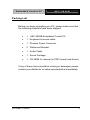
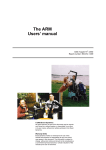
Packing List
Before you begin operating your PC, please make sure that
the following materials have been shipped:
•
1
•
1 Keyboard & mouse cable
•
1 Phoenix Power Connector
•
2 Wallmount Bracket
•
1 Audio Cable
•
1 Screw Package
•
1 CD-ROM for manual (in PDF format) and drivers
AEC-6820B Embedded Control PC
If any of these items should be missing or damaged, please
contact your distributor or sales representative immediately.
AEC-6820B User Manual
4
Embedded Control PC
AEC-6820B
Safety & Warranty
1. Read these safety instructions carefully.
2. Keep this user's manual for later reference.
3. Disconnect this equipment from any AC outlet before cleaning.
Do not user liquid or spray detergents for cleaning. User a
damp cloth.
4. For a pluggable equipment, the power outlet must be installed
near the equipment and must be easily accessible.
5. Keep this equipment away from humidity.
6. Put this equipment on a reliable surface during installation.
Dropping it or letting it fall could cause damage.
7. The openings on the enclosure are for air convection. Protect
the equipment from overheating. DO NOT COVER THE
OPENINGS.
8. Make sure the voltage of the power source is correct before
connecting the equipment to the power outlet.
9. Position the power cord so that people cannot step on it. Do not
place anything over the power cord.
10. All cautions and warnings on the equipment should be noted.
11. If the equipment is not used for a long time, disconnect it from
the power source to avoid damage by transient over-voltage.
12. Never pour any liquid into an opening. This could cause fire or
electrical shock.
13. Never open the equipment. For safety reasons, only qualified
service personnel should open the equipment.
14. If any of the following situations arises, get the equipment
checked by service personnel:
AEC-6820B User Manual
5
Embedded Control PC
AEC-6820B
a. The power cord or plug is damaged.
b. Liquid has penetrated into the equipment.
c.
The equipment has been exposed to moisture.
d. The equipment does not work well, or you cannot get it
to work according to the users manual.
e. The equipment has been dropped and damaged.
f.
The equipment has obvious signs of breakage.
15. DO NOT LEAVE THIS EQUIPMENT IN AN ENVIRONMENT
WHERE THE STORAGE TEMPERATURE IS BELOW -20°C
(-4°F) OR ABOVE 60°C (140°F). IT MAY DAMAGE THE
EQUIPMENT.
FCC Safety
This device complies with Part 15 FCC Rules.
Operation is subject to the following two
conditions: (1) this device may not cause
harmful interference, and (2) this device must
accept any interference received including
interference that may cause undesired
operation.
Caution:
It may cause danger of explosion if battery is incorrectly replaced.
Replace only with the same or equivalent type recommended by
the manufacturer. Dispose of used batteries according to the
manufacturer’s instructions.
AEC-6820B User Manual
6
Embedded Control PC
AEC-6820B
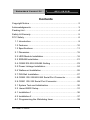
Contents
Copyright Notice ..............................................................................2
Acknowledgments............................................................................3
Packing List .....................................................................................4
Safety & Warranty............................................................................5
FCC Safety ......................................................................................6
1.1 Introduction............................................................................9
1.2 Features ..............................................................................10
1.3 Specifications ...................................................................... 11
2.1 Dimension ...........................................................................15
2.2 HDD Module Installation......................................................16
2.3 SDRAM Installation .............................................................21
2.4 COM2 RS-232/422/485 Setting ..........................................23
2.5 Power Linkage Installation ..................................................24
2.6 Wallmount Installation .........................................................26
2.7 DIN Rail Installation.............................................................27
2.8 COM2 RS-232/422/485 Serial Port Connector ..................28
2.9 COM1 RS-232 Serial Port Connector ................................28
3.1 System Test and Initialization ..............................................30
3.2 Award BIOS Setup .............................................................31
4.1 Installation 1 ........................................................................36
4.2 Installation 2 ........................................................................37
A.1 Programming the Watchdog timer ......................................39
AEC-6820B User Manual
7
Embedded Control PC
AEC-6820B
Chapter
1
General
Information
AEC-6820B User Manual
8
Embedded Control PC
AEC-6820B
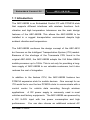
1.1 Introduction
The AEC-6820B is an Embedded Control PC with PCMCIA slots
that supports different interfaces with wireless functions. Antivibration and high temperature tolerances are the main design
features of the AEC-6820B. This allows the AEC-6820B to be
installed in a rugged transportation environment despite high
ambient vibration and temperature.
The AEC-6820B continues the design concept of the AEC-6810
but focuses on the Intelligent Transportation System (ITS) market.
Because of the shortage of the Transmeta CPU found in the
original AEC-6820, the AEC-6820B adopts the VIA Eden EBGA
mobile processor up to 1GHz. This is not only for providing a longterm supply of AEC-6820B to our valuable customers, but it also
reduces the cost of integration.
In addition to the fanless CPU, the AEC-6820B features two
PCMCIA expansion slots for mobile devices. One concept for an
ITS would be to use the two PCMCIA slots to communicate with a
control center for vehicle data recording through wireless
applications.
A DC power supply is commonly used in most
vehicles and factory equipments. The AEC-6820B can powered by
a DC 9~30V input with low power consumption and high
performance.
You can also choose an additional external AC
AEC-6820B User Manual
9
Embedded Control PC
AEC-6820B
power adapter for power redundancy purposes. AAEON provides
flexible power choices for customers who choose the AEC-6820B.
Transportation has become part of most people’s life and forms a
necessary part of their lifestyle. From cars to trains to ships and
airplanes, we rely on those tools a lot.
The AEC-6820B is
designed to improve transportation control and enhance the quality
of our lives.
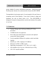
1.2 Features
•
Fanless Design with VIA Eden 667MHz/C3 1GHz
processor
•
2 PCMCIA slots for expansion
•
DC 9~30V input with Phoenix connector and optional
external AC power adapter
•
Front accessible USB port for system control and data
transfer
•
WinCE.net / CFD / Optional 2.5” HDD kit
•
Ethernet /2 COM / 4 USB / Audio
•
Operating Temperature: -15°C ~65°C (-5°F~149°F)
•
Anti-vibration up to 6 g rms / Anti-shock up to 100g
•
CE / FCC class B certified
AEC-6820B User Manual
10
Embedded Control PC
AEC-6820B
1.3 Specifications
System
•
CPU:
VIA Eden 667MHz / C3 1GHz
•
Memory:
SDRAM SODIMM x 1, Max.
512MB
•
Expansion:
PCMCIA x 2
•
VGA:
D-sub 15 VGA Connector
•
Keyboard/Mouse: PS/2 Keyboard & Mouse
•
Ethernet:
10/100Base-TX Ethernet RJ-45
connector x 1
•
SSD:
•
Hard Disk Storage: Optional 2.5” Slim HDD Module
•
Serial Port:
1 x RS-232, 1 x RS-232/422/485
•
Audio:
Mic-in / Line-in / Line-out, by
Type II CompactFlash™ slot
extension cable
•
USB:
4 USB 1.1 Ports
•
Parallel Port:
1 Parallel Port
•
Watchdog Timer:
Generates a time-out system reset
•
Power Supply:
DC Input: 9V DC~30V DC
AC Input: External Power Adapter
(Optional)
•
System Control:
Power on / off switch x 1;Reset
button x 1
•
Indicator:
AEC-6820B User Manual
Power LED x 1
11
Embedded Control PC
AEC-6820B
HDD active LED x 1
Mechanical and Environmental
•
Construction:
Aluminum Alloy chassis
•
Color:
Dark Blue
•
Mounting:
Wallmount (Default), DIN-Rail
•
Dimension:
8.35” (W) x 2.53” (H) x 4.21” (D)
212.15mm x 64.2mm x 107mm
•
Net Weight:
4.75lb (2.16kg)
•
Gross Weight:
8.36lb (3.8kg)
•
Operation Temperature:
5°F ~ 149°F (-15°C ~ 65°C)(CFD)
•
Operation Humidity: 5~95%@40°C, non-condensing
•
Vibration:
6 g rms / 5~500Hz / random
operation (Without HDD Module)
1 g / 5~500Hz / random operation
(With HDD Module)
•
Shock:
100g peak acceleration (11 msec.
duration)
•
EMC:
AEC-6820B User Manual
CE/FCC class B
12
Embedded Control PC
AEC-6820B
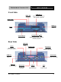
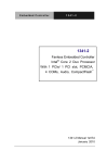
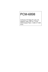
Front Side
PCMCIA x 2
HDD LED
With lockable design for
anti-vibration purpose
Power LED
USB Port
Reset
USB 1.1
Power Switch
CompactFlash™ Slot
With lockable design for antivibration purpose
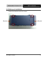
Rear Side
USB Port
USB 1.1
Audio
Parallel Port
Serial Port
Mini-DIN 9-pin
Line-out/In, MIC-in
D-sub 25-pin
D-sub 9-pin
RS-232/422/485
USB Port
Power Inlet
USB 1.1
Phoenix connector
Ethernet
RJ-45, 10/100
Serial Port
KB/MS
VGA
D-sub 9-pin
RS-232
Mini-DIN 6-pin
D-sub 15-pin
AEC-6820B User Manual
13
Embedded Control PC
AEC-6820B
Chapter
2
Hardware
Installation
AEC-6820B User Manual
14
Embedded Control PC
AEC-6820B
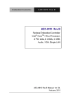
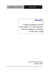
2.1 Dimension
240.0
222.0
212.2
AEC-6820B
107.0
85.0
5
R2.
64.9
70.9
Units:mm
DC-IN
A EC-6820
Reset
HDD
SYS
PCMCIA
USB
USB
AUDIO
USB
PRINTER
COM2
GND
Vin
Power
LAN
10.0
COM1
KB/MS
VGA
107.0
130.0
AEC-6820B User Manual
15
Embedded Control PC
AEC-6820B
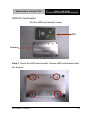
2.2 HDD Module Installation
Cable Insertion
Step 1: Open the HDD cover by loosening the screws on the
bottom of the chassis.
AEC-6820B User Manual
16
Embedded Control PC
AEC-6820B
Step 2: Insert the Cable to the bottom of the chassis as the
illustration below.
PIN 1
AEC-6820B User Manual
17
Embedded Control PC
AEC-6820B
HDD Kit Combination
Get the HDD and bracket ready.
HDD
Bracket
Step 1: Stack the HDD and bracket. Fasten HDD and bracket with
the screws.
AEC-6820B User Manual
18
Embedded Control PC
AEC-6820B
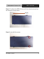
Step 2: Fasten the HDD module into the HDD kit house.
Step 3: Insert the other side of the cable to the HDD module.
AEC-6820B User Manual
19
Embedded Control PC
AEC-6820B
Step 3: Combine the HDD kit house with the chassis and push as
the illustration shown below.
Push
Step 4: Lock with the screws.
AEC-6820B User Manual
20
Embedded Control PC
AEC-6820B
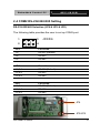
2.3 SDRAM Installation
Step 1: Screw the lid off the chassis.
AEC-6820B User Manual
21
Embedded Control PC
AEC-6820B
Step 2: Remove the lid and insert the SDRAM SODIMM module
into the slot.
SDRAM
SODIMM
module
AEC-6820B User Manual
22
Embedded Control PC
AEC-6820B
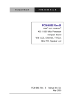
2.4 COM2 RS-232/422/485 Setting
RS-232/422/485 Selection (JP4 & JP5 & JP6)
The following table provides the user to set up COM2 port.
1
5
2
6
JP4
JP4/5/6
Function
1-2
RS-232 (Default)
3-4
RS-422
5-6
RS-485
JP5
Function
1-3,2-4
RS-232 (Default)
3-5,4-6
RS-422
3-5,4-6
RS-485
JP6
Function
1-3,2-4
RS-232 (Default)
3-5,4-6
RS-422
3-5,4-6
RS-485
JP4
JP5/JP6
AEC-6820B User Manual
23
Embedded Control PC
AEC-6820B
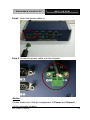
2.5 Power Linkage Installation
Step 1: Get the cable and connector ready
Step2: Fix the connector to the cable with the screws.
AEC-6820B User Manual
24
Embedded Control PC
AEC-6820B
Step3: Insert the power cable in.
Step 4: Screw the power cable into the chassis.
Notice:
Please make sure that pin assignment of Power and Ground
on the accurate location.
AEC-6820B User Manual
25
Embedded Control PC
AEC-6820B
2.6 Wallmount Installation
Fasten the brackets with the screws.
Bracket
AEC-6820B User Manual
Bracket
26
Embedded Control PC
AEC-6820B
2.7 DIN Rail Installation
Step 1: Fix the DIN Rail kit with the screws on the chassis as the
illustration shown.
DIN Rail Kit
Step 2: Press the DIN Rail on the DIN Rail kit to fix it.
DIN Rail
AEC-6820B User Manual
27
Embedded Control PC
AEC-6820B
2.8 COM2 RS-232/422/485 Serial Port Connector
Different devices implement the RS-232/422/485 standard in
different ways. If you are having problems with a serial device, be
sure to check the pin assignments below for the connector.
4
2
5
1
6
9
7
8
Pin
Signal
Pin
Signal
1
DCD (422TXD-/485DATA-)
2
RXD (422RXD+)
3
TXD (422TXD+/485DATA+)
4
DTR (422RXD-)
5
GND
6
DSR
7
RTS
8
CTS
9
RI
10
N.C.
2.9 COM1 RS-232 Serial Port Connector
Pin
Signal
Pin
Signal
1
DCD
2
RXD
3
TXD
4
DTR
5
GND
6
DSR
7
RTS
8
CTS
9
RI
10
N.C.
AEC-6820B User Manual
28
Embedded Control PC
AEC-6820B
Chapter
3
Award BIOS
Setup
AEC-6820B User Manual
29
Embedded Control PC
AEC-6820B
3.1 System Test and Initialization
These routines test and initialize board hardware. If the
routines encounter an error during the tests, you will either
hear a few short beeps or see an error message on the
screen. There are two kinds of errors: fatal and non-fatal.
The system can usually continue the boot up sequence with
non-fatal errors. Non-fatal error messages usually appear on
the screen along with the following instructions:
Press <F1> to RESUME
Write down the message and press the F1 key to continue
the boot up sequence.
System configuration verification
These routines check the current system configuration
against the values stored in the CMOS memory. If they do
not match, the program outputs an error message. You will
then need to run the BIOS setup program to set the
configuration information in memory.
There are three situations in which you will need to change
the CMOS settings:
1. You are starting your system for the first time
2. You have changed the hardware attached to your
system
3. The CMOS memory has lost power and the configuration
information has been erased.
The AEC-6820B CMOS memory has an integral lithium
battery backup for data retention. However, you will need to
replace the complete unit when it finally runs down.
AEC-6820B User Manual
30
Embedded Control PC
AEC-6820B
3.2 Award BIOS Setup
Awards BIOS ROM has a built-in Setup program that allows
users to modify the basic system configuration. This type of
information is stored in battery-backed CMOS RAM so that it
retains the Setup information when the power is turned off.
Entering Setup
Power on the computer and press <Del> immediately. This
will allow you to enter Setup.
Standard CMOS Features
Use this menu for basic system configuration. (Date, time,
IDE, etc.)
Advanced BIOS Features
Use this menu to set the advanced features available on
your system.
AEC-6820B User Manual
31
Embedded Control PC
AEC-6820B
Advanced Chipset Features
Use this menu to change the values in the chipset registers
and optimize your system performance.
Integrated Peripherals
Use this menu to specify your settings for integrated
peripherals. (Primary slave, secondary slave, keyboard,
mouse etc.)
Power Management Setup
Use this menu to specify your settings for power
management. (HDD power down, power on by ring, KB
wake up, etc.)
PnP/PCI Configurations
This entry appears if your system supports PnP/PCI.
PC Health Status
This menu allows you to set the shutdown temperature for
your system.
Frequency/Voltage Control
Use this menu to specify your settings for auto detect
DIMM/PCI clock and spread spectrum.
Load Fail-Safe Defaults
Use this menu to load the BIOS default values for the
minimal/stable performance for your system to operate.
Load Optimized Defaults
AEC-6820B User Manual
32
Embedded Control PC
AEC-6820B
Use this menu to load the BIOS default values that are
factory settings for optimal performance system operations.
While AWARD has designated the custom BIOS to
maximize performance, the factory has the right to change
these defaults to meet their needs.
Set Supervisor/User Password
Use this menu to set Supervisor/User Passwords.
Save and Exit Setup
Save CMOS value changes to CMOS and exit setup.
Exit Without Saving
Abandon all CMOS value changes and exit setup.
You can refer to the "AAEON BIOS Item Description.pdf"
file in the CD for the meaning of each setting in this
chapter.
AEC-6820B User Manual
33
Embedded Control PC
AEC-6820B
Chapter
4
Driver
Installation
AEC-6820B User Manual
34
Embedded Control PC
AEC-6820B
The AEC-6820B comes with a CD-ROM which contains most
of drivers and utilities of your needs.
There are several installation ways depending on the driver
package under different Operating System application.
If you utilize Windows NT series OS, you are strongly
recommended to download the latest version Windows NT
Service Pack from Microsoft website and install it before
installing any driver.
Please follow the sequence below to install the
drivers:
Step 1 – Install System Driver
Step 2 – Install VGA Driver
Step 3 – Install Audio Driver
Step 4 – Install LAN Driver
For installation procedures of each driver, you may refer to
section 4.1 to 4.2.
AEC-6820B User Manual
35
Embedded Control PC
AEC-6820B
4.1 Installation 1
Applicable for Windows 2000/98/ME/XP
1. Insert the AEC-6820B CD-ROM into the CD-ROM Drive.
2. From the CD-ROM, select the desired component Driver
folder, and then select the desired Operation System
folder to double click on the Setup.exe icon. A driver
installation screen will appear.
Notice:
Take VGA driver installation under Windows 98 for example,
choose the corresponding folder depending on your OS.
3. A driver installation screen will appear, please follow the
onscreen instructions to install the driver in sequence
and click on the Next button.
Notice:
In some cases the system will ask you to insert Windows 98
CD ROM and key in its path. Then click on the OK button to
key in path.
4. Click on the Finish button to finish installation process.
And allow the system to reboot.
AEC-6820B User Manual
36
Embedded Control PC
AEC-6820B
4.2 Installation 2
Applicable for Windows 2000/ 98/ME/XP
1. Insert the AEC-6820B CD-ROM into the CD-ROM Drive.
2. Click on Start button, select the Settings, and then click
on the Control Panel icon.
3. Double click on the Add/Remove Hardware icon and
Add New Hardware Wizard will appear. Click on the
Next button.
4. Select Search for the best driver for your device
(Recommended) and click on the Next button.
5. Select Specify a location, click on Have Disk button
then key in the CD-ROM path and specify component
drivers and OS folders. Then click on the Next button.
6. The Wizard shows that Windows driver file search for the
device. Click on the Next button.
7. The system will ask you to insert Windows 98 CD ROM.
Click on the OK button to insert CD-ROM and key in
path.
8. Click on the OK button.
9. Click on the Finish button to finish installation process.
And allow the system to reboot.
AEC-6820B User Manual
37
Embedded Control PC
AEC-6820B
Appendix
A
Programming the
Watchdog Timer
AEC-6820B User Manual
38
Embedded Control PC
AEC-6820B
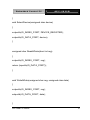
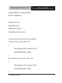
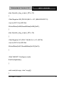
A.1 Programming the Watchdog timer
AEC-6820B contains a watchdog timer reset pin. (GP16)
All reference material can be found on the following pages.
==================================================*
*
** Title : WatchDog Timer Setup Utility (for W83977 GP16)
** Company : AAEON Technology Inc.
** Compiler : Borland C ++ Version 3.0
**
**
**
**=================================================
=============*/
#include <dos.h>
#include <io.h>
#include <bios.h>
#include <stdio.h>
#include <stdlib.h>
#include <conio.h>
/* Set I/O Address : 370/371 or 3F0/3F1 */
AEC-6820B User Manual
39
Embedded Control PC
#define IO_INDEX_PORT
0x370
#define IO_DATA_PORT
0x371
AEC-6820B
/* Set Watchdog reset pin : 12/13/16 */
#define watch_dog_output_GP 16
#define UNLOCK_DATA
#define LOCK_DATA
0x87
0xAA
#define DEVICE_REGISTER 0x07
void EnterConfigMode()
{
outportb(IO_INDEX_PORT, UNLOCK_DATA);
outportb(IO_INDEX_PORT, UNLOCK_DATA);
}
void ExitConfigMode()
{
outportb(IO_INDEX_PORT, LOCK_DATA);
AEC-6820B User Manual
40
Embedded Control PC
AEC-6820B
}
void SelectDevice(unsigned char device)
{
outportb(IO_INDEX_PORT, DEVICE_REGISTER);
outportb(IO_DATA_PORT, device);
}
unsigned char ReadAData(short int reg)
{
outportb(IO_INDEX_PORT, reg);
return (inportb(IO_DATA_PORT));
}
void WriteAData(unsigned char reg, unsigned char data)
{
outportb(IO_INDEX_PORT, reg);
outportb(IO_DATA_PORT, data);
}
AEC-6820B User Manual
41
Embedded Control PC
AEC-6820B
void SetWatchDogTime(unsigned char time_val)
{
EnterConfigMode();
SelectDevice(8);
//Set Register F2
//Set Watch-Dog Timer 1~ 256
WriteAData(0xF2, time_val);
// set counter counts in second (or minute)
// Register F4 Bit 6 = 0/1 (minutes/seconds)
// For w83977EF only
WriteAData(0xF4, 0x40);
ExitConfigMode();
}
void init_w83977tf_aw_watchdog()
{
short int value;
AEC-6820B User Manual
42
Embedded Control PC
AEC-6820B
//Enter W83977 Configure Mode
EnterConfigMode();
//Select Device 7
SelectDevice(7);
//Set Device Active
WriteAData(0x30, 0x01);
//caution:skip this step will be a mistake!!
if (watch_dog_output_GP==12)
{
//Set Register E2 to define GP12
WriteAData(0xE2, 0x0A);
}
else if(watch_dog_output_GP==13)
{
//Set Register E3 to define GP13
WriteAData(0xE3, 0x0A);
}
AEC-6820B User Manual
43
Embedded Control PC
AEC-6820B
else if(watch_dog_output_GP==16)
{
//Set Register E6 to define GP16
WriteAData(0xE6, 0x0A);
}
//Select Device 8
SelectDevice(8);
//Set Register F3
//keyboard and mouse interrupt reset Enable
//When Watch-Dog Time-out occurs,Enable POWER LED output
WriteAData(0xF3, 0x0E);
//caution:skip this step will be a mistake!!
if (watch_dog_output_GP==12)
{
//Set Register 2A (PIN 57) Bit 7 = 0/1 (KBLOCK/GP12)
//set to GP12 for WD Rst
WriteAData(0x2A,ReadAData(0x2A)|0x80);
}
AEC-6820B User Manual
44
Embedded Control PC
AEC-6820B
else if(watch_dog_output_GP==13)
{
//Set Register 2B (PIN 58) Bit 0 = 0/1 (KBLOCK/GP13)
//set to GP13 for WD Rst
WriteAData(0x2B,ReadAData(0x2B)|0x01);
}
else if(watch_dog_output_GP==16)
{
//Set Register 2C (PIN 119) Bit 5-4 = 01 (GP16)
//set to GP16 for WD Rst
WriteAData(0x2C,ReadAData(0x2C)|0x10);
}
//Exit W83977 Configure mode
ExitConfigMode();
}
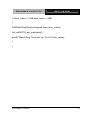
void main(int argc, char* argv[])
{
AEC-6820B User Manual
45
Embedded Control PC
AEC-6820B
int time_value=0;
char *ptr;
printf(“winBond 83977 WatchDog Timer Setup Utility Version 1.0
\n" );
printf(“Ccopyright (c) 2000 AAEON Technology Inc.\n");
printf(“Tthis version only for W83977 that using GP%d to Reset
System.\n",watch_dog_output_GP);
if (argc == 1)
{
printf(“\n Syntax: WATCHDOG [time] \n" );
printf(" time range : 1 ~ 256 \n\n" );
return ;
}
if (argc > 1)
{
ptr = argv[1];
time_value = atoi(ptr);
}
AEC-6820B User Manual
46
Embedded Control PC
AEC-6820B
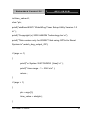
if (time_value > 0 && time_value < 256)
{
SetWatchDogTime((unsigned char) time_value);
init_w83977tf_aw_watchdog();
printf(“Watch Dog Timer set up : %d \n",time_value);
}
}
AEC-6820B User Manual
47