1
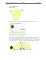
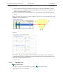
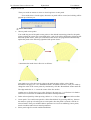
SESAM
USER MANUAL
HYDROMESH
User controlled free surface meshing
for HydroD
DET NORSKE VERITAS
SESAM
User Manual
HydroMesh
User controlled free
surface meshing
1 June 2010
Valid for HydroMesh version 2.0
Developed and Marketed by
DET NORSKE VERITAS
Copyright © 2010 Det Norske Veritas
All rights reserved. No part of this book may be reproduced, in any form or by any means,
without permission in writing from the publisher.
Published by:
Det Norske Veritas Software
Veritasveien 1
N-1322 HØVIK
Norway
Telephone: +47 67 57 99 00
Facsimile: +47 67 57 72 72
E-mail, sales: [email protected]
E-mail, support: [email protected]
Website: www.dnvsoftware.com
If any person suffers loss or damage which is proved to have been caused by any negligent act or omission of Det Norske Veritas, then Det Norske Veritas
shall pay compensation to such person for his proved direct loss or damage. However, the compensation shall not exceed an amount equal to ten times the
fee charged for the service in question, provided that the maximum compensation shall never exceed USD 2 millions. In this provision “Det Norske Veritas”
shall mean the Foundation Det Norske Veritas as well as all its subsidiaries, directors, officers, employees, agents and any other acting on behalf of Det
Norske Veritas.
DET NORSKE VERITAS SOFTWARE
Program version 2.0
HydroMesh
User Manual
1
1 June 2010
HydroMesh User Manual
Table of Contents
INTRODUCTION............................................................................................................................................................. 2
1.1
1.2
1.3
OVERVIEW ...................................................................................................................................................................................... 2
HYDROMESH IN THE SESAM SYSTEM .............................................................................................................................................. 2
TERMINOLOGY AND NOTATION ....................................................................................................................................................... 2
2.
HYDROMESH APPLICATION ............................................................................................................................ 3
2.1
2.2
INTRODUCTION ............................................................................................................................................................................... 3
COMMAND LINE ARGUMENTS .......................................................................................................................................................... 3
3.
HYDROMESHSETUP APPLICATION ............................................................................................................... 4
3.1
3.2
3.3
3.4
INTRODUCTION ............................................................................................................................................................................... 4
COMMAND LINE ARGUMENTS .......................................................................................................................................................... 4
APPLICATION WINDOW ................................................................................................................................................................... 4
USER INTERFACE............................................................................................................................................................................. 5
3.4.1
Menu Items & Tool Bar Buttons........................................................................................................................ 5
Menu Items............................................................................................................................................................. 5
Tool Bar Buttons.................................................................................................................................................... 5
3.4.2 Control panel..................................................................................................................................................... 6
•
Surface boundary shape ........................................................................................................................................ 6
•
Total surface size (vessel lengths).......................................................................................................................... 6
•
Channel Mesh Resolution. ..................................................................................................................................... 7
3.4.3 Properties Editing Area..................................................................................................................................... 8
•
Split line properties editor ..................................................................................................................................... 8
•
Patch Properties Editor ......................................................................................................................................... 9
3.4.4 Operating Area................................................................................................................................................ 11
3.4.5 Status Bar Area ............................................................................................................................................... 14
•
•
3.5
•
•
3.6
INTEGRATION WITH HYDROD........................................................................................................................................................ 15
Alternative 1......................................................................................................................................................... 15
Alternative 2......................................................................................................................................................... 15
DATA ORGANIZATION.................................................................................................................................................................... 15
3.6.1
3.6.2
HydroMeshSetup input/output files ................................................................................................................. 15
HydroMesh input/output files .......................................................................................................................... 15
DET NORSKE VERITAS SOFTWARE
Program version 2.0
HydroMesh
User Manual
2
1 June 2010
INTRODUCTION
1.1
Overview
HydroMesh is an alternative application to wasim_mesh, the mesh generating program for Wasim. The
HydroMesh application computes both the model and free surface mesh. A graphical user interface called
HydroMeshSetup is used to define/generate free surface mesh.
1.2
HydroMesh in the Sesam System
HydroMesh is integrated into the HydroD/SESAM system, it can also be run as a stand along program
using input files created by Wasim or an XML file (free surface settings file) generated by
HydroMeshSetup.
1.3
Terminology and Notation
LMB:
RMB:
PLN:
SSG:
GEO:
FEM:
XML:
HydroMeshSetup:
Left mouse button
Right mouse button
File format for sectional hull geometry
File format for meshes
File format for irregular meshes
General SIF file format (irregular meshes)
File format for free surface mesh settings (waterline/split line coordinates, meshresolution etc.)
User interface for HydroMesh for generating and editing free surface mesh
configuration file.
DET NORSKE VERITAS SOFTWARE
Program version 2.0
HydroMesh
User Manual
3
1 June 2010
2. HYDROMESH APPLICATION
This chapter provides an overview of the HydroMesh application.
2.1
Introduction
The idea about HydroMesh is to generate a free surface mesh for a section model, where the mesh
parameters are controlled by the user. After reading in the waterline from an SSG file, automatically
generated by wasim_mesh or HydroMesh, the free surface will be cut into user defined mesh patches.
SSG/GEO/FEM/XML files will be used to store the final mesh data.
2.2
Command line arguments
HydroMesh execution:
HydroMesh.exe “filename”_fs.xml
This should generate the free surface and hull mesh files (SSG, GEO, FEM).
DET NORSKE VERITAS SOFTWARE
Program version 2.0
HydroMesh
User Manual
4
1 June 2010
3. HYDROMESHSETUP APPLICATION
3.1
Introduction
HydroMeshSetup is used to read in waterline coordinates, divide the free surface into user defined
patches and finally store the result in an XML file. This XML file could be read into HydroMeshSetup
again for further editing.
3.2
Command line arguments
HydroMeshSetup execution:
HydroMeshSetup.exe “filename”_dry.ssg “filename”_fs.xml
If the surface settings file exists, the settings will be imported, otherwise the file will be created.
3.3
Application Window
DET NORSKE VERITAS SOFTWARE
HydroMesh
User Manual
5
1 June 2010
Program version 2.0
3.4
User interface
3.4.1
•
Menu Items & Tool Bar Buttons
Menu Items
1. “Open …” menu item
When choose “Open…” a file open dialog will appear, in which the file type is fixed.
Fixed file types
2. “Save” menu item
Save the free surface setting into xml configuration file, the file name is ended with *_fs.xml.
3. “Exit” menu item
Exit the HydroMeshSetup.exe.
•
Tool Bar Buttons
Open file button. Shortcut: Ctrl + O
Save file button, available only when changing has been made. Shortcut: Ctrl + S
Select split line mode, click to select split line to edit its properties. Shortcut: S
Select patch mode, click to select a patch to edit its properties. Shortcut: P
DET NORSKE VERITAS SOFTWARE
HydroMesh
User Manual
6
1 June 2010
Program version 2.0
Draw lines mode button, click in operating area to draw a split line. Shortcut: D
Create patch mode button, click in closed region to create a mesh patch. Shortcut: C
Delete mode button. Delete selected patch or split line. Shortcut: E
Scale content to window button, click to zoom the free surface to fit the window. Shortcut: F
Mirror the model button, available only when the model is not symmetric. Shortcut: M
Clear mesh button, remove all user defined patches and split lines. Shortcut: L
3.4.2
•
Control panel
Surface boundary shape
Select the shape of the free surface boundary condition shape, you could choose either circular
or rectangular boundary shape.
•
Aspect Ratio Check
You could check the aspect ratio of the free surface patch as follows:
When you press the “Check” button, any invalid patch whose aspect ratio is less than the
value specified in the above TextBox will be highlighted in red color.
•
Total surface size (vessel lengths)
The surface size value decides the size of the free surface, by default the radius is 5 vessel
lengths, the width is 10, and the height is 5, the depth is 5.
DET NORSKE VERITAS SOFTWARE
HydroMesh
User Manual
7
1 June 2010
Program version 2.0
•
Channel Mesh Resolution.
This could change the mesh resolution for the both sides of channel at the girth wise and
longitudinal direction, you could only examine the mesh resolution visually from HydroD:
1. Mesh Resolution Setting from HydroMesh
2. 3D Mesh Visualization in HydroD
DET NORSKE VERITAS SOFTWARE
Program version 2.0
3.4.3
HydroMesh
User Manual
8
1 June 2010
Properties Editing Area
The properties editing area contains two editors: Split line properties editor and Patch properties
editor.
•
Split line properties editor
Select a split line (high lighted in yellow), the editor will shows in the properties editing area.
The coordinates of any point could be changed manually, simply by clicking the point on the
list then enter the new coordinates in the textboxes.
Click the point
Change the coordinates
The point’s location can be changed by dragging it as well.
Select the point and drag
DET NORSKE VERITAS SOFTWARE
Program version 2.0
•
HydroMesh
User Manual
9
1 June 2010
Patch Properties Editor
Patch Resolution
When a patch is selected in the operating area, the patch properties editor will shows up.
Mesh resolution can be changed by input new values in the textbox as shown in the picture
above. The corner points’ group box shows corner points coordinates (not editable).
It’s highly recommended that the corner order of the currently edited patch in the operating
area matches exactly as the corner order displayed in the Patch Resolution tab as follows:
DET NORSKE VERITAS SOFTWARE
Program version 2.0
HydroMesh
User Manual
10
1 June 2010
As above pictures shows, the edge marked from 0 – 1 for each four patches in four different
quadrants are near the centre of the free surface physical domain.
In order to achieve this, you could click the “RotatePatch” button; it will rotate the corner 900
around the counter clockwise direction for each click as follows:
00
900
1800
2700
The edges tab page shows how many points are from waterline on each edge.
Stretch Condition
“Stretch Condition” tab page could define the point distribution (stretching) for a specified
edge. The stretch function HydroMesh uses is:
[
]
tanh Q(1 − η * )
s = Pη + (1 − P)(1 −
)
tanh Q
*
The following is the definition for each column:
Edge: List the four edges which you could define stretch condition for.
P: This parameter controls the slope of the distribution, usually you could choose a value
between 2 ~ 5 inclusive.
DET NORSKE VERITAS SOFTWARE
HydroMesh
User Manual
11
1 June 2010
Program version 2.0
Q: This parameter controls the departure from linearity, by default, HydroMesh use linear
spline interpolation to equally divide the patch edge based on the mesh resolution you set
from the “Mesh Resolution” tab page.
Reverse Orientation: This could which direction / orientation the point distribution should
follow.
When you select edge from the “Stretch Condition” tab page, the corresponding edge will be
highlighted in the operating area:
Poisson
In “Poisson” tab page, you could control the interior mesh orientation both at radial and
circumferential direction, HydroMesh uses the following Poisson control function for both
radial and circumferential mesh control:
P = Q = −ae − c
3.4.4
Operating Area
Draw Lines mode
You can go to the “Draw Line Mode” by press the
•
Draw split line (see 3.4.1 Button bar)
button in the toolbar.
DET NORSKE VERITAS SOFTWARE
Program version 2.0
HydroMesh
User Manual
12
1 June 2010
* Split line shows in red when creating, and will not take effort before “Enter” or
“whitespace” key is pressed.
•
Draw orthogonal (horizontal or vertical) split lines by pressing shift key when moving the
mouse to draw the lines as follows:
•
The program will automatically snap to the intersecting points when you move the mouse near
those points as follows:
* The red circle will be displayed when point are snapped.
Select Split Line Mode
You can go to the “Select Split Line Mode” by press the
button in the toolbar.
•
Move split line nodes (see 3.4.3 Split line properties editor)
•
Select split line using mouse
•
Delete selected split line[s] by either pressing “delete” or “e” key or press
toolbar.
•
Multi select split lines by pressing “shift” key, then subsequently use mouse to select lines.
button in the
Create Patch Mode
You could go to the “Create Patch Mode” by clicking the button in the toolbar.
DET NORSKE VERITAS SOFTWARE
Program version 2.0
HydroMesh
User Manual
13
1 June 2010
Then you could use mouse to select to closed regions to create patch.
* You could select a closed region; otherwise no patch will be created, and a dialog will be
popped up to inform you:
Select Patch Mode
•
Moves patch corner points.
You could drag one of the patch corner points to the desired intersecting points for the patch,
when you drag the corner near a specified point, a red circle will be displayed as following left
hand side picture shows, when you could release the mouse, the program will automatically
update the patch as the following right hand side picture shows:
* Sometimes the mesh doesn’t like nice as follows:
One simply way to fix this issue is going to the patch property editor, select “Mesh
Resolution” tab page (see 3.4.3 “Patch Resolution” for further reference). Then you could try
change the order of the corner points by continuously click the “RotatePatch” button until the
The edge marked as 0 – 1 is near the centre of the free surface.
Another way to fix this issue is go to the “Poisson” tab page (see “3.4.3 Poisson” for further
reference) to control the circumferential and radial control parameters.
•
Delete selected patch by either pressing “delete” or “e” key or press
•
Create patch. You could create patch in “Select Patch Mode” by pressing shift key, then use
the mouse to pick up a closed region to create patch, after the patch is created, it will be in
selected mode. Then you could do further operations on it such as redefining corner points,
stretch condition and Poisson control parameters.
•
Select patch edge for stretch condition definition.
button in the toolbar.
DET NORSKE VERITAS SOFTWARE
Program version 2.0
HydroMesh
User Manual
14
1 June 2010
When a patch is selected, you could move the cursor near one of its patch edge to select the
edge, then the “Stretch Condition” tab page will be displayed, the subsequent operation is the
same as specified in 3.4.3 “Stretch Condition”.
•
Copy & Paste patch properties.
If you want to share patch property settings across different patches, you could select a source
patch first, then press CTRL + C to copy those patch properties into clipboard, then select
another patch, press CTRL+ V to paste the patch properties to the destination patch, then the
two patches will share the same patch property settings.
Show Mirrored Mesh (only when section model is symmetric, see 3.4.1 Button bar)
* The mirrored patches are displayed in white colour.
3.4.5
Status Bar Area
•
The left hand side of the status bar shows the “helper message” telling you the different
operations you could perform in each mode, “Draw Split Lines” mode, “Create Patch” mode
etc.
•
The right hand side of the status bar displays the coordinates of cursor position.
DET NORSKE VERITAS SOFTWARE
Program version 2.0
3.5
HydroMesh
User Manual
15
1 June 2010
Integration with HydroD
•
Alternative 1
The “Settings…” button starts the HydroMeshSetup application, and generate “filename”_fs.xml
file after quit, then HydroMesh will read the XML file and generates data files (see section 3.6).
•
Alternative 2
An existing SectionMesh can also be edited by selecting the “Edit surface mesh settings...” item
on the right click menu. This will start the HydroMeshSetup program, and regenerate the mesh
when the program finishes.
3.6
Data organization
3.6.1
•
HydroMeshSetup input/output files
Input
“filename”_dry.ssg: dry hull mesh file.
“filename”_fs.xml: user defined free surface mesh setting file.
•
Output
“filename”_fs.xml: user defined free surface mesh setting file.
3.6.2
•
HydroMesh input/output files
Input
“filename”.pln: section model hull geometry file.
“filename”_fs.xml: user defined free surface mesh setting file.
DET NORSKE VERITAS SOFTWARE
Program version 2.0
•
HydroMesh
User Manual
16
1 June 2010
Output
Dry hull mesh file: “filename”_dry.ssg and “filename”_dry.geo (irregular mesh file)
Wet hull mesh file: “filename”_wet:ssg and “filename”_wet.geo (irregular mesh file)
Free surface mesh file: “filename”_fs.ssg and “filename”_fs.geo (irregular mesh file)
Combined mesh file (free surface & wet hull)
“filename”.ssg and “filename”.geo (irregular mesh file)
Files using SIF file format:
T7301.FEM (Dry hull)
T7302.FEM (Wet hull)
T7303.FEM (Free surface)
T7310.FEM (T7301 + T7302 + T7303) + mirror images in the case of symmetry
T7320.FEM (TT7301 + T7302)
T7373.FEM (Mesh of free surface in global coordinates system)
T7374.FEM (Symmetric free surface mesh, it will be generated only when the model is
symmetric)