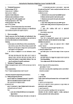
1
PL-1, Pocket Logger 1 2 PL-1 .......................................................................................................... 2 Wiring ....................................................................................................... 3 2.1.1 Single Innovate Device Relay Wiring Instructions ..................... 3 3 Mounting .................................................................................................. 4 4 Connecting the PL-1 to the MTS serial chain .......................................... 4 5 Recording ................................................................................................. 5 6 LogWorks ................................................................................................. 6 6.1 MTS channel setup ........................................................................... 6 6.2 Import Log File .................................................................................. 6 6.3 Erasing the Log from the memory card ............................................ 7 7 Error Codes (Status light blink sequences) ............................................. 7 Appendix A: Limited Warranty ........................................................................ 8 11-0135B 1 PL-1 The PL-1 is designed to be easily integrated with the rest of your Innovate Motorsports MTS (Modular Tuning System) devices for easy data logging. The unit records up to 32 channels of information while only utilizing 1mb of memory per 17 minutes data. The following screens will help you get familiar with the unit. Record Trigger/ Status Light Used to start and stop a record session. Button illuminates to display unit’s status. SD Memory Card Slot MTS Input Connection from the MTS OUT of the last MTS device is feed into this input. Remote Record Trigger Input for optional cable used to trigger the start and stop of a record session remotely. Power Switched 12V and ground input. 2 2 Wiring 1. Connect the RED wire from the power cable to a switched 12V source. A switched 12V source comes ON as soon as the ignition on the car is keyed on. Make sure the connection is fused with a minimum fuse size of 1A. Circuits that share power with the vehicle’s stereo, ignition system, ECU, lighting, or fuel pump should not be used. When in doubt, create an additional circuit using an automotive relay available at any automotive parts supplier. See the next section for a relay installation diagram. 2. Connect the BLACK wire from the power cable to a ground source. Ideally, all Innovate Motorsports MTS devices should share the same ground source. Avoid noisy ground sources, such as grounds used for the radio and/or ignition. 3. Connect the power cable to the port on the back of the PL-1 labeled “Power”. 2.1.1 Single Innovate Device Relay Wiring Instructions 3 3 Mounting The Pl-1 can be mounted upside down, vertically, and right-side up without any ill effect. Double-sided mounting tape works best. Special consideration should given to the amount of vibration on the mounting surface and the proximity to devices with the potential to throw RF (ignition, radio, etc). Lastly, allow enough slack on the connected cables so that there be no strain on the PL-1’s connectors. 4 Connecting the PL-1 to the MTS serial chain The PL-1 can be added to any Innovate Motorsports’ MTS log chain. Below are some examples: The Innovate Motorsports’ MTS (Modular Tuning System) allows you to daisy chain multiple devices (gauges or sensor input boxes) to form one single synchronous log. MTS chains can consist of a single unit connected directly to a laptop, two units, or multiple devices connected together, up to 32 channels. 4 Innovate Motorsports’ MTS devices have two types of serial interface connectors, the legacy 2.5mm stereo and the 4 pin Molex. The following patch cables are available to interface your devices together: 4 Pin Molex to 4 Pin Molex - 4ft p/n 3846 2.5mm to 2.5mm Stereo - 4ft p/n 3760 2.5mm to 2.5mm Stereo - 6in p/n 3789 4 Pin Molex to 2.5mm Stereo - 4ft p/n 3812 Each MTS device has a Serial IN and a Serial OUT port. To create an MTS chain, make sure power is OFF to all devices. Connect the serial OUT of the first device (device all the way to the left using the examples above) to the serial IN of the second device in the serial chain. Continue chaining the serial OUT to the serial IN until all devices are married together. In the case of the PL-1, you will only find one MTS port (serial IN) since data from the MTS chain does not need to travel out. If either the LC-1, LMA-3, or DL-32 are the first device in the MTS chain, a terminator plug should be inserted to the serial IN. All other devices should have nothing connected to the serial IN if they are first in the MTS chain. Avoid connecting or disconnecting any of the MTS ports labeled IN or OUT while the unit is powered ON. 5 Recording Once the PL-1 has been connected to the MTS chain, insert the memory card included with your kit into the SD memory card slot in the PL-1. Power ON the PL-1 along with the other MTS devices. When the PL-1 is first powered ON, it will give you a series of quick flashes indicating it is ON. The unit will then initialize the memory card, during this time the status light will not be lit. Once the memory card is initialized successfully, the status light will light up and remain solid. The PL-1 is now ready to record. Pressing the Record button (or on the optional record trigger) will start a record session. The status light will display a steady fast blink. Press the Record button a second time to stop the record session. Even though the PL-1 can recover from power interruption, it is best to press the record button to stop recording BEFORE power is interrupted. If power is interrupted you may lose the active recording session and/or corrupt the log. DO NOT REMOVE THE MEMORY CARD WHILE A RECORD SESSION IS IN PROGRESS. DOING SO MIGHT CORRUPT THE 5 FILE SYSTEM ON THE MEMORY CARD AND CAUSE ALL THE DATA TO BE LOST. THE MEMORY CARD WILL ALSO NEED TO BE REFORMATTED TO WORK AGAIN. If the status light starts blinking a sequence (blink sequence followed by a pause) refer to the Error Code chapter. If there is no memory card inserted in the PL-1, the unit will not light up the status light. You will only see the initial series of quick flashes when the unit is first powered ON. 6 LogWorks Before your first recording, it is advisable to first setup and configure your MTS chain in LogWorks. Connecting the MTS chain to LogWorks will allow the software to identity which devices are in the MTS chain. Once LogWorks is configured, data from the memory card will correctly represented as it was configured. 6.1 MTS channel setup 1. The PL-1 does not have a MTS out, necessary to connect the MTS chain to a computer, so it must first be removed from the MTS chain. Connect the second to-last device in the MTS chain to the computer (the device that was previously connected to the PL-1.) 2. Launch LogWorks and power up all the devices in the MTS chain. 3. In the LogWorks software, click File/Connect. A “Serial Connection” dialog box will appear and allow you to select the right COM port. Click Connect. 4. LogWorks will now identify the products connected to the MTS chain. 5. Configure your individual inputs to match each device’s function. Refer to the LogWorks manual for more details. 6. Once the inputs have been configured you may optionally save your input description by going to File/Save Input Description. 7. You can now import your log file. 6.2 1. 2. 3. 4. Import Log File Remove the memory card from the PL-1’s SD memory card slot. Connect the SD card reader to a USB port on your Windows machine. Insert the memory card into the SD card reader. Windows will usually pop up a windows with the contents of the memory card, if this does not happen you can go directly to the drive under “My Computer.” 5. In the memory card you will find a file named “Log.d32”. Double-click on this file and LogWorks will automatically open it. Please note that the single log file can contain multiple sessions. Every time a record session is triggered a new session is amended to the log file. 6 6.3 1. 2. 3. 4. Erasing the Log from the memory card Remove the memory card from the PL-1’s SD memory card slot. Connect the SD card reader to a USB port on your Windows machine. Insert the memory card into the SD card reader. Windows will usually pop up a windows with the contents of the memory card, if this does not happen you can go directly to the drive under “My Computer.” 5. In the memory card you will find a file named “Log.d32”. Select this file and click the delete button on your keyboard. If prompted, confirm that you want to delete the file. 7 Error Codes (Status light blink sequences) Blink Sequence 2 3 4 Error Code SD Card - File system initiation and function failed. SD Card - Write Protect is switched ON MTS Data Error - MTS serial communication error. Solution 5 MTS Data Error – Iinitialization error 6 SD Card – Write Error 7 MTS Data Error 8 SD Card – could not open log file for writing Missing or Corrupt Firmware 9 7 Card not formatted Memory card failure Memory card incompatible Move the write protect switch to the OFF position Power OFF all MTS devices and verify that all serial connections are fully seated. Connect MTS devices individually to LogWorks software and verify serial communication. Verify that total number of channels on the MTS serial chain does not surpass 32. Card not formatted Memory card full Memory card failure Memory card failure Verify number of channels is no more 32 Card not formatted Memory card failure Contact Innovate Motorsports Support Appendix A: Limited Warranty LIMITED WARRANTY Innovate stands behind the quality of its products. Innovate makes the following warranty to purchasers of its products: All new Innovate products carry a one year warranty from the date of purchase. If proof of purchase cannot be provided, warranty will be determined by date of manufacture. When Warranty Void This warranty shall terminate and Innovate shall have no obligation pursuant to it if (i) your Innovate product has been modified or repaired in a manner not previously authorized by Innovate in writing, (ii) the identification markings on your Innovate product have been removed, defaced, or altered; (iii) your Innovate product was subjected to accident, abuse, shipping damage, or improper use; (iv) your Innovate product was not used or configured as specified in the product manual; or (v) your Innovate product was subjected to operating conditions more severe than those specified in the product manual. Repairs Under This Warranty In the unlikely event that your Innovate hardware product should prove defective during the warranty period, contact Innovate Customer Support for a return material authorization (RMA) at (800) 348 3037. Products returned for service must be securely packed to prevent damage and shipped charges pre paid, along with proof of purchase and the return material authorization form, to the Innovate repair location as instructed by Customer Service. Innovate within a reasonable amount of time from its receipt of your product so shipped, will ship to you, at its option, the repaired product or a new or reconditioned product of comparable or greater specified functionality. All repaired or replacement products shall be warranted for the remainder of the original product warranty. Disclaimer INNOVATE MAKES NO OTHER EXPRESS OR IMPLIED WARRANTY WITH RESPECT TO YOUR INNOVATE PRODUCT OTHER THAN THE LIMITED WARRANTY SET FORTH ABOVE. No Innovate dealer, agent, or employee is authorized to make any modification, extension, or addition to this warranty, unless enforceable or unlawful under applicable law, INNOVATE DISCLAIMS ALL IMPLIED WARRANTIES, INCLUDING THE IMPLIED WARRANTIES OF MERCHANTABILITY, NONINFRINGEMENT, AND FITNESS FOR A PARTICULAR PURPOSE, AND THE LIABILITY OF INNOVATE, IF ANY, FOR DAMAGES RELATING TO ANY ALLEGEDLY DEFECTIVE PRODUCT SHALL UNDER ANY TORT, CONTRACT, OR OTHER LEGAL THEORY BE LIMITED TO THE ACTUAL PRICE PAID FOR SUCH PRODUCT AND SHALL IN NO EVENT INCLUDE INCIDENTAL, CONSEQUENTIAL, SPECIAL, OR INDIRECT DAMAGES OF ANY KIND EVEN IF INNOVATE IS AWARE OF THE POSSIBILITY OF SUCH DAMAGES. Some states do not allow limitations on how long an implied warranty lasts or the exclusion or limitation of incidental or consequential damages, so the above limitations or exclusions may not apply to you. 8