1
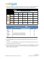
PART #: NETB12WR
User Manual and Installation Guide
The WireRat™ (Part # NETB12WR) is designed for the monitoring of electrically driven pivots
only. For hydraulically driven pivots, please refer to the user manual and installation guide
for part # NETB12TL.
Copyright © 2012 Net Irrigate, LLC. All rights
reserved.
This publication may not be
reproduced in part, without prior written
consent from Net Irrigate, LLC. Net Irrigate, LLC
makes no representations or warranties with
respect to the contents hereof and specifically
disclaim any implied warranties or merchantability for any particular purpose. Net Irrigate, LLC reserves
the right to revise this publication and to make changes from time to time in the content hereof without
obligation to notify any person or organization of such changes.
NetIrrigate®, WireRat™ and its associated logos are registered trademarks of Net Irrigate, LLC. Other
trademarks, trade names, and logos published in this manual belong to their respective owners.
Revision History
Rev
Date
Description
A
November 6th, 2012
Initial release of manual.
B
December 10th, 2012
Updated wiring diagrams.
Customer Support:
Email: [email protected]
Phone: (800) 961-9549 x2
www.netirrigate.com
Business Address:
Net Irrigate, LLC
4201 E 3RD ST
Bloomington, IN 47401
STANDARD HARDWARE & SOFTWARE TERMS AND CONDITIONS
1.
Grant of License. Subject to Customer paying all amounts payable hereunder, Net Irrigate, LLC ("Net Irrigate") grants to Customer a
non-exclusive, nontransferable license during the term hereof to use the software embedded in NetIrrigate® branded products (the "NETB12s")
for irrigation systems owned by Customer (the “Licensed Software”) for Customer's internal monitoring and data processing needs.
2.
Ownership of the Licensed Software. Net Irrigate shall retain title to and ownership of the Licensed Software. Net Irrigate reserves
all rights not expressly granted herein. The Licensed Software may not be used beyond the scope of the license expressly granted herein.
Customer shall keep the Licensed Software confidential. Customer may not alter, modify, or adapt the Licensed Software or documentation,
including, but not limited to, translating, reverse engineering, decompiling, disassembling, or creating derivative works. Customer shall
promptly report any infringement of the Licensed Software of which it becomes aware, and shall cooperate with Net Irrigate in protecting Net
Irrigate’s proprietary rights in the Licensed Software.
3.
Term and Termination. This Agreement shall take effect upon the delivery of the NETB12s to the Customer, and shall terminate 99
(ninety-nine) years from therefrom.
4.
Warranties and Liability. CUSTOMER ACKNOWLEDGES AND AGREES THAT NET IRRIGATE SHALL HAVE NO LIABILITY ARISING FROM
THE OPERATION OR USE OF THE NETB12s FOR SPECIAL, INDIRECT, CONSEQUENTIAL, EXEMPLARY, PUNITIVE, OR INCIDENTAL DAMAGES
(INCLUDING LOSS OF DATA, REVENUE, PROFITS, CROPS OR OTHER ECONOMIC ADVANTAGE), EVEN IF IT HAS BEEN ADVISED OF THE POSSIBILITY
OF SUCH DAMAGES, AND EVEN IF SUCH DAMAGES ARE DIRECTLY OR INDIRECTLY CAUSED BY NEGLIGENCE OR A TORT COMMITTED BY NET
IRRIGATE, ITS AGENTS, OR ITS ASSIGNS. THE MAXIMUM LIABILITY OF NET IRRIGATE TO ANY PERSON, FIRM OR CORPORATION WHATSOEVER
ARISING OUT OF OR IN THE CONNECTION WITH ANY LICENSE, USE OR OTHER EMPLOYMENT OF THE NETB12S, WHETHER SUCH LIABILITY
ARISES FROM ANY CLAIM BASED ON BREACH OR REPUDIATION OF CONTRACT, BREACH OF WARRANTY, TORT, OR OTHERWISE, SHALL IN NO
CASE EXCEED THE EQUIVALENT OF THE PRICE PAID BY THE CUSTOMER FOR THE NETB12S. THE ESSENTIAL PURPOSE OF THIS PROVISION IS TO
LIMIT THE POTENTIAL LIABILITY OF THE PARTIES ARISING FROM THIS AGREEMENT. THE PARTIES ACKNOWLEDGE THAT THE LIMITATIONS SET
FORTH IN THIS SECTION 4 ARE INTEGRAL TO THE AMOUNT OF CONSIDERATION LEVIED IN CONNECTION WITH THE LICENSE OF THE SERVICE
AND THAT, WERE NET IRRIGATE TO ASSUME ANY FURTHER LIABILITY OTHER THAN AS SET FORTH HEREIN, SUCH CONSIDERATION WOULD OF
NECESSITY BE SET SUBSTANTIALLY HIGHER. CERTAIN STATES AND/OR JURISDICTIONS DO NOT ALLOW THE EXCLUSION OF IMPLIED
WARRANTIES OR LIMITATIONS OF LIABILITY FOR INCIDENTAL OR CONSEQUENTIAL DAMAGES, SO THE EXCLUSIONS SET FORTH ABOVE MAY NOT
APPLY TO YOU.
5.
Government Rights. The Licensed Software is Commercial Computer Software under Federal Government Acquisition Regulations
and agency supplements to them. If the Licensed Software is provided to the Federal Government and/or its agencies, it is provided only under
the Restricted Rights Provision of the Federal Acquisition Regulations applicable to Commercial Computer Software developed at private
expense and not in the public domain. The use, duplication, or disclosure by the Federal Government and/or its agencies is subject to
restrictions as set forth in subdivision (c)(ii) of the Rights and Technical Data and Computer Software clause at DFARS 252.227-7013 and FAR
52.227-19(c).
6.
Export Controls. Customer acknowledges that the licensing and distribution of the Licensed Software is subject to the export control
laws and regulations of the United States of America, and any amendments thereof, which restrict exports and re-exports of software, technical
data, and direct products of technical data. Customer agrees that it will not export or re-export any Licensed Software, or any information or
documentation related thereto, directly or indirectly, without first obtaining permission to do so as required from the United States of America
Department of Commerce’s Bureau of Export Administration, or other appropriate governmental agencies, to any countries, end-users, or for
any end uses that are restricted by U.S. export laws and regulations, and any amendments thereof.
Miscellaneous. Customer may not assign, transfer, or delegate any of its rights, duties or obligations hereunder, in whole or in part,
without the prior written consent of Net Irrigate. Customer shall not disclose the terms and conditions of this Agreement, except as may be
required to implement and enforce the terms of this Agreement, or as may be required by legal procedures or by law. In all matters relating to
this Agreement, Customer and Net Irrigate shall act as independent contractors. This Agreement shall be governed, construed, and interpreted
under the laws of the State of Indiana, to the exclusion of any conflict of law or choice of law rule or principle that might refer construction or
interpretation of this Agreement to the substantive law of another jurisdiction. Any action to enforce this Agreement or for breach of this
Agreement shall be brought in a state or federal court situated in Marion County, Indiana, and each of the parties hereby consents to personal
jurisdiction of and venue in such courts, and waives any future right to object to this designation of jurisdiction and venue. The waiver or
failure of any party to exercise in any respect any right provided for under this Agreement shall not be deemed a waiver of any future right
hereunder. This Agreement shall bind the parties, their permitted successors, heirs, and assigns. No provision of this Agreement which may be
found to be unenforceable shall in any way invalidate any other provision or provisions of this Agreement, all of which shall remain in full force
and effect. Any ambiguities in this Agreement shall not be strictly construed against the drafter of the language concerned but shall be
resolved by applying the most reasonable interpretation under the circumstances, giving full consideration to the intentions of the parties at
the time of contracting. There are no representations, promises, warranties or understandings relied upon by Customer which are not
contained herein. Customer shall be responsible for any and all taxes applicable to this Agreement, excluding taxes on the income of Net
Irrigate. In any collection action or litigation relating to this Agreement, Net Irrigate shall be entitled to recover its costs of collection or
litigation, including reasonable attorney’s fees. This Agreement and the Net Irrigate User Agreement constitute the entire understanding
between the parties with respect to the subject matter hereof, and cancels, terminates, and supersedes any prior agreement or understanding
relating to the subject matter hereof between Net Irrigate and Customer. Any modifications to this Agreement must be in writing and signed
by both parties.
7.
NET12WR User Manual and Installation Guide (Rev. B)
Page 2 of 21
Copyright 2012 © Net Irrigate, LLC
Contents
Applications................................................................................................................................................... 4
Getting Started.............................................................................................................................................. 5
Identifying the Device Id ........................................................................................................................... 5
Package Contents...................................................................................................................................... 5
Bench Testing ............................................................................................................................................ 6
Customer, Site, and Notification Recipient Setup .................................................................................... 6
Functional Principles ..................................................................................................................................... 7
Battery Backup .......................................................................................................................................... 7
Span Cable Theft Detection ...................................................................................................................... 7
Safety Stop Alerts ...................................................................................................................................... 7
Remote Shutdown .................................................................................................................................... 7
GPS Monitoring ......................................................................................................................................... 8
Pivot Heading ........................................................................................................................................ 8
Virtual Stop-In-Slots .............................................................................................................................. 8
Installation .................................................................................................................................................... 9
Checking the Pivot .................................................................................................................................... 9
Mounting and Wiring the NETB12WR ...................................................................................................... 9
Testing Procedures ..................................................................................................................................... 11
Simulating Span Cable Cuts..................................................................................................................... 11
Primary Method .................................................................................................................................. 11
Alternative Method............................................................................................................................. 12
Testing Safety Stop Notifications ............................................................................................................ 13
Testing Remote Shutdown...................................................................................................................... 13
Testing GPS ............................................................................................................................................. 14
Appendix A – Valley Branded Pivots Wiring Diagram ................................................................................. 15
Appendix B – Zimmatic Branded Pivots Wiring Diagram ............................................................................ 16
Appendix C – Reinke Branded Pivots Wiring Diagram ................................................................................ 17
Appendix D – Lockwood Pivots Wiring Diagram ......................................................................................... 18
Appendix E – Pierce Branded Pivots Wiring Diagram ................................................................................. 19
Appendix F – Common Causes of Low Ground Resistance......................................................................... 20
Appendix G – Troubleshooting False Alarms .............................................................................................. 21
Applications
Part # NETB12WR (branded the WireRat™) is specifically designed to be mounted on the end tower of
any brand of electrically driven center pivot. Once installed and properly configured, the NETB12WR
provides the following remote monitoring functions:
Span Cable Theft
Notifications
The NETB12WR is the only copper theft alarm product that works seamlessly with all
brands of pivots and requires no external power. The NETB12WR utilizes a patentpending supervisory circuit that works strictly on lithium battery power for 3 to 5
years. When a pivot’s span cable is cut or tampered with, the NETB12WR sends
instant text, voice, or email notifications that a possible theft is occurring.
Pivot Safety Stop
Notifications
When a pivot transitions from walking to stopped, the NETB12WR can send text, voice,
or email notifications that the pivot’s safety circuit has opened.
Remote Shutdown
The NETB12WR contains a normally closed relay which can be wired in series with the
pivot’s safety circuit. Once configured, the normally closed relay can be actuated via a
phone call to our interactive voice response system by calling 800-961-9549x7.
GPS Monitoring and
Virtual Stop-In-Slot
Notifications
The NETB12WR facilitates graphically monitoring the heading of a center pivot via a
website. In addition, the NETB12WR can be used to provide virtual stop-in-slot alerts
such that text, voice, email notifications, or remote shutdown commands are sent
when a pivot reaches desired field headings.
Example: The
NETB12WR can send
notifications or stop the
pivot when the heading
is at 270 degrees.
NET12WR User Manual and Installation Guide (Rev. B)
Page 4 of 21
Copyright 2012 © Net Irrigate, LLC
Getting Started
Identifying the Device Id
All NETB12 products are uniquely identified by a 6 digit serial number which is barcoded on both the
packaging carton and the physical unit. Net Irrigate refers to this number as the “Device Id”.
Package Contents
All NETB12WR units ship with:
1.
2.
3.
4.
5.
A ½” NPT Cord Grip to be used with the knock out on the pivot’s end tower box.
Magnetic mounts which come pre-installed on the enclosure.
A 24” heavy duty UV resistant nylon cable tie for safety-securing the unit.
A wire nut which may need to be used if wiring the NETB12WR up for remote shutdown purposes.
An extra Device Id bar code sticker which can be placed on the panel of the center pivot so the
associated Device Id can be identified at the pivot pad.
NET12WR User Manual and Installation Guide (Rev. B)
Page 5 of 21
Copyright 2012 © Net Irrigate, LLC
Bench Testing
The NETB12WR should be bench tested before being installed on an actual pivot. A simple bench
testing procedure ensures a properly functioning unit and adequate wireless coverage. Bench testing
involves the following procedure:
1. Identify the Device Id of the NETB12WR. Recall that the serial number is barcoded on the bottom of
the unit to the right of the cord grip.
2. Use your cell phone to text the phrase “TEST XXXXXX” to 317-602-1732. Where XXXXXX is the serial
number of the unit. Example “TEST 333001”.
3. You should receive a text message back from our server within 60 seconds that says: “333001 is
ready for bench testing. Hold White and GND wire together and then break bond. You will be
notified in three minutes when test completes.”
4. Follow the instructions texted to you by holding the White and GND (green) wires together and then
breaking the circuit. This action will initiate a diagnostic test on the unit and will text you when
complete. The entire test should take about 3 minutes.
5. Within 3 minutes, you should receive the text message: “Bench test successful. Device 333001 is
functioning properly and registered on the NetIrrigate network.”
6. If you receive an error message from our server or do not receive a text message indicating success
within 3 minutes, please contact customer support at (800) 961-9549 x2.
Customer, Site, and Notification Recipient Setup
Before mounting the NETB12WR on an actual pivot, it is best to setup the customer information, the
irrigation site details, and the intended notification recipients in the NetIrrigate™ system. Additionally,
you will need to link this information to the Device Id you intent to mount. Setup is fast and easy and
can be accomplished through one of three possible ways:
1. Login to www.netirrigate.com. If you do not yet have a username and password for your dealership,
please contact customer support at (800) 961-9549 or email [email protected]. For details
on how to utilize the dealer portal on www.netirrigate.com, please review the document entitled
“Web Portal User Guide”.
2. Login to the WireRat™ iPhone App. WireRat™ is available in the App Store. You may use the same
login information as you would use to login to www.netirrigate.com. For information on how to use
the iPhone app, please review the document entitled “WireRat™ iPhone App User Guide”.
3. If you do not have access to a computer or the WireRat™ iPhone App, just contact customer support
at (800) 961-9549 and an agent will setup the customer, site, and notification recipients for you.
“Notification recipients” are the people who are contacted (either via voice call, text message, or email)
when cable cut, safety-stop, or virtual stop-in-slot events occur at the pivot. Up to ten notification
recipients can be configured per pivot. Notification recipients can be easily enabled or disabled by using
the web portal, iPhone app, or simply by calling customer support at (800) 961-9549.
NET12WR User Manual and Installation Guide (Rev. B)
Page 6 of 21
Copyright 2012 © Net Irrigate, LLC
Functional Principles
Battery Backup
The NETB12WR utilizes a custom designed lithium battery pack which is designed to operate the interval
cellular radio modem for at least three years. Expected battery life could be as long as five years
depending on environmental conditions and frequency of pivot operation. A working battery is
imperative for proper functionality. The battery can be tested by following the bench testing
procedures of the previous page.
Span Cable Theft Detection
The NETB12WR checks for cut wire by sending a small supervisory current through the neutral and
ground conductors of the pivot’s span cable. When this supervisory current is interrupted, an alarm
code is triggered. The supervisory current is generated by the internal NETB12WR batteries and works
seamlessly with normal pivot operation. For the span cable alarm to properly arm itself, at least 50,000
ohms of resistance must exist between the ground and neutral conductors when separated at the
control transformer or outgoing side of the collector ring.
Safety Stop Alerts
The NETB12WR transmits safety stop notifications when it detects a closed-to-open transition in a
pivot’s 120VAC safety circuit. The NETB12WR must see the circuit open for at least 40 seconds before
transmitting a wireless notification that the circuit transitioned from closed-to-open. The time delay is
to prevent false alarms due to loose wires, pivot jogging, and auto-reverse functionality. On nonstandard pivots, paralleling off of any 120VAC control circuit that is hot when the pivot is running (in
both forward and reverse) will suffice in monitoring for safety stops.
Remote Shutdown
If the NETB12WR is wired correctly, it may be used to remotely stop a center pivot. Each NETB12WR is
equipped with a normally closed control relay. When a remote shutdown call is initiated, the coil on this
control relay is wirelessly picked up, thereby interrupting the normally closed safety circuit. When the
NETB12WR senses the 120VAC supplied by the pivot panel has dropped out, the coil of the relay deenergizes, and the contact closes again thereby allowing the pivot to restart.
For remote shutdown functionality to properly work, the NETB12WR must remain ON until the pivot
completely drops out. The NETB12WR must still receive 120VAC from the main pivot panel until the
delay timer in the pivot drops out.
The remote-shutdown functionality utilizes the red wire in the NETB12WR connection cord. If wiring for
remote shutdown is not desired, tape off the red wire and do not put the safety circuit in series with the
NETB12WR. Instead, just parallel the black wire in the NETB12WR connection cord to the appropriate
120VAC safety circuit OR connect the black and blue wires to the respective forward and reverse
terminals of the pivot. To avoid shorts, be sure to properly tape or cap off the red wire on the NETB12WR if
the unit is not being wired for remote shutdown purposes.
NET12WR User Manual and Installation Guide (Rev. B)
Page 7 of 21
Copyright 2012 © Net Irrigate, LLC
GPS Monitoring
Pivot Heading
The NETB12WR sends longitude and latitude coordinates to the NetIrrigate® servers every 15 minutes.
If the longitude and latitude coordinates of the pivot pad are properly entered as part of the site details,
the software on the server will use basic trigonometry to determine the angle or “heading” of the pivot.
Determining the longitude and latitude coordinates of the pivot pad can be accomplishes with several
smart phone apps, most consumer GPS devices, or even the WireRat™ iPhone app. Alternatively, you
may contact customer support at (800) 961-9549 and an agent will attempt to locate the pad of the
pivot using Google Earth.
Virtual Stop-In-Slots
Because the NetIrrigate® servers are monitoring the heading of the pivot, notifications can be
configured when the pivot reaches a desired a heading. Likewise, the pivot can be configured to
automatically shut down when a desired heading is met. Up to 16 different virtual stop-in-slot points
can be configured. Virtual stop-in-slot points can be configured via the NetIrrigate® web portal or by
calling customer support at (800) 961-9549.
Sample Virtual Stop-In-Slot Configuration Screen on netirrigate.com
NET12WR User Manual and Installation Guide (Rev. B)
Page 8 of 21
Copyright 2012 © Net Irrigate, LLC
Installation
Checking the Pivot
If the span cable theft alarm function of the NETB12WR will be utilized, it is best to confirm the
resistance between the ground and neutral conductors on the pivot. Recall that the span cable alarm is
activated when the bond between the neutral control circuit conductor and the equipment grounding
conductor is broken.
1. Locate the control transformer in the pivot control panel. Remove the
bonding wire (green) from terminal X2 on the control transformer.
Re-tighten the terminal screw to hold the remaining neutral wires
(white) in place on X2.
2. If the pivot is equipped with a modern relay board, disconnect the clip
to the relay board that contains ground and neutral conductors.
3. Using an analog ohmmeter, measure the resistance between the
bonding wire (green) and terminal X2 (white) on the control
transformer. The measured resistance should be greater than 50k
(50,000) ohms. If the measured resistance is greater than 50k ohms,
replace the bonding wire (green) on terminal X2 of the control
transformer and proceed to mounting the NETB12WR on the end
tower of the pivot. If the measured resistance is less than 50k ohms
see Appendix F entitled “Common Causes of Low Ground Resistance”.
Mounting and Wiring the NETB12WR
Ideally, the NETTB11 should be mounted on the end tower of a pivot. This provides for greatest
accuracy when utilizing GPS services. Likewise, mounting on the end tower provides for maximum
protection against span cable theft.
1. Ensure power to the pivot is completely off and the control panel is locked.
2. Climb the tower of the pivot and allow the powerful magnets on the back of the NETB12WR to
adhere to the angle iron of the pivot. The NETB12WR should be
positioned vertically.
3. Remove the cover from the tower electrical box.
4. If the bottom of the tower box is not equipped with a standard ½”
NPT knock-out, drill an appropriate hole to fit the black ½” NPT cord
grip which is included in the NETB12WR packaging.
5. Install the supplied cord grip and lock nut.
6. Run the tray cable from the NETB12WR through the cord grip and into the tower box.
NET12WR User Manual and Installation Guide (Rev. B)
Page 9 of 21
Copyright 2012 © Net Irrigate, LLC
7. Follow the appropriate wiring diagram depending on the brand of pivot. Refer to the tables below.
If installing on a pivot brand not listed, please contact customer support at (800) 961-9549.
For setups WITHOUT implementation of remote-shutdown functionality
NETB12WR Wire Color
Black
(120VAC In)
Blue
(120VAC In)
Red (NC Relay
Out – 120VAC)
White (Neutral)
Green (GND)
Yellow-Red
Unused
(Tape Off)
Unused
(Tape Off)
White
Grounding Bar
Zimmatic
Brown
Unused
(Tape Off)
Unused
(Tape Off)
White
Grounding Bar
Reinke
Purple
Pink
Unused
(Tape Off)
White
Grounding Bar
Lockwood
Yellow
Orange
Unused
(Tape Off)
White
Grounding Bar
Pierce
Yellow
Unused
Unused
(Tape Off)
White
Grounding Bar
Pivot Brand
Wire Color
Valley
For setups in which remote-shutdown functionality WILL be implemented, see wiring
diagram in the respective Appendix listed below
Pivot Brand
Additional Relays Needed?
Appendix Page #
Valley
No
A
15
Zimmatic
No
B
16
Reinke
Yes (only required for remote shutdown)
C
17
Lockwood
Yes (only required for remote shutdown)
D
18
Pierce
No
E
19
8. Once the NETB12WR wires are connected to the appropriate terminals, replace the cover on the
tower box.
9. If necessary, zip-tie the NETB12WR tray cable away from the mechanical levels beneath the tower
electrical box to avoid kinks or obstructions.
10. Wrap the included 24” heavy duty UV resistant nylon cable tie around the NETB12WR unit for added
security. While the mounting magnets are extremely strong, the cable tie is designed to protect
against extremely severe weather.
NET12WR User Manual and Installation Guide (Rev. B)
Page 10 of 21
Copyright 2012 © Net Irrigate, LLC
Testing Procedures
Simulating Span Cable Cuts
Before testing the cut wire alarm, at least one notification recipient should be configured for the site in
question. If this has not been done, please see previous section Customer, Site, and Notification
Recipient Setup. Once it is determined that a notification has been configured for a span cable cut event,
follow the procedure below:
Primary Method
1. Go to the main panel at the pad and ensure the power to the panel is completely off.
2. Open both panel doors such that the control transformer within the pivot panel can be accessed.
3. If the pivot panel is equipped with a relay board, disconnect the clip to the relay board which may
contain a neutral and ground conductor.
4. Locate X-2 on the control transformer. This is where the white and green wires are bonded.
5. Remove the terminal screw and separate the white wire and the ground wire for at least 5 seconds.
6. Replace the wires and be sure to re-tighten the terminal screw.
7. Wait at least 3 minutes for a text, voice, or email alert which indicates a possible theft is occurring.
If an alert is not received, try testing with the alternative method on the following page.
NET12WR User Manual and Installation Guide (Rev. B)
Page 11 of 21
Copyright 2012 © Net Irrigate, LLC
Alternative Method
1. Ensure power to the pivot is off and the control panel is locked.
2. Walk to the first drive tower, climb it, and remove the tower box cover.
3. Note the terminal numbers of where each wire is connected. There are two gauges of wire in the
tower box. The smaller wire is what you will be working with. The span cable heading out toward
the end tower is what will need to be disconnected sequentially.
4. Remove each 120VAC control circuit wire. This includes: safety, forward, reverse, percent timer,
and end gun. REMOVE THE WHITE NEUTRAL CONDUCTOR LAST.
5. Wait at least 30 seconds and replace the wires to their respective terminals.
6. Replace the tower box cover.
7. Wait at least 3 minutes for a text, voice, or email alert which indicates a possible theft is occurring.
If an alert is not received please contact customer support at (800) 961-9549.
NET12WR User Manual and Installation Guide (Rev. B)
Page 12 of 21
Copyright 2012 © Net Irrigate, LLC
Testing Safety Stop Notifications
Before testing for safety stop notifications, at least one notification recipient should be configured for
the site in question. If this has not been done, please see previous section Customer, Site, and
Notification Recipient Setup.
If desired, safety stop notifications can be configured for when the pivot both starts up and stops
walking. Once it is determined that notification recipients have been configured for each respective
alert, follow the procedure below:
1. Start the pivot walking in either forward or reverse.
2. In about three minutes, you should receive a message that says “{NetIrrigate Site Name} is now
running.” Where {NetIrrigate Site Name} is the alias you’ve given to the irrigation site.
3. Once you receive the notification that the system is running, stop the pivot.
4. Within three minutes, you should receive a message that says “{NetIrrigate Site Name} has stopped
walking.”
5. Repeat the process by walking the pivot in the opposite direction. To ensure proper functionality, it
is important to walk the pivot in BOTH directions.
6. If any of the notifications fail, please contact customer support at (800) 961-9549.
Testing Remote Shutdown
Remotely shutting down the pivot is accomplished through the NetIrrigate® Remote Shutdown Line.
The NetIrrigate® Remote Shutdown Line uses caller id security to identify your list of pivots available for
remote shutdown. To enable your phone to initiate remote shutdown calls, make sure your phone
number exists and is enabled within the Remote Access tab within the NetIrrigate® Web Portal.
To initiate a remote shutdown call, simply dial (800) 961-9549 x7. The automated system will read off a
list of your pivots available for remote shutdown. Follow the voice prompts and your pivot should shut
down within two minutes. You will receive a safety stop notification if remote shutdown is successful.
NET12WR User Manual and Installation Guide (Rev. B)
Page 13 of 21
Copyright 2012 © Net Irrigate, LLC
Testing GPS
Successful GPS monitoring begins by ensuring the latitude and longitude of the pivot pad have been
entered into the NetIrrigate® servers. The latitude and longitude of the pad may either be entered via
the WireRat™ iPhone app or via the site details tab in the NetIrrigate® web portal:
To acquire an initial pivot heading, run the pivot for at least 15 minutes. Once a GPS fix is established,
the pivot heading should update on the Site Status report within the NetIrrigate® web portal.
If a virtual stop-in-slot alert is configured, the notification will trigger when the pivot is within 3 degrees
of either side of the configured heading. For example, if a virtual stop-in-slot notification is configured
at 90°, the stop-in-slot notification will occur when the NETB12WR periodically reports latitude and
longitude which results in the heading of the pivot to be between 87° and 93°. The tolerance window is
designed to compensate for the wide variance in pivot speeds and percent timer settings.
NET12WR User Manual and Installation Guide (Rev. B)
Page 14 of 21
Copyright 2012 © Net Irrigate, LLC
Appendix A – Valley Branded Pivots Wiring Diagram
1.
2.
3.
4.
5.
6.
Remove the yellow-red wire from the load side of the terminal strip.
Connect the red wire from the NETB12WR to terminal 9 where the yellow-red wire was.
Wire-nut the removed yellow-red wire to the black wire on the NETB12WR.
Connect the white wire on the NETB12WR to terminal 7 (neutral).
Connect the green wire on the NEB12WR to Ground.
The blue wire on the NETB12WR is unused and should be taped off.
NETB12WR
Connection
Cord
Valley Center Pivot
Terminal Strip
End Tower Box
WHITE
Yellow-Red from
Inner Tower
Unused
(cap off)
BLK
RED
BLUE
black
1
blue
2
red
3
yellow
4
brown
5
orange
6
white
7
yellow
8
Yel-Red
9
purple
10
pink
11
Manual
Power
Disconnect
GREEN
Grounding Bar
NET12WR User Manual and Installation Guide (Rev. B)
Page 15 of 21
Copyright 2012 © Net Irrigate, LLC
Appendix B – Zimmatic Branded Pivots Wiring Diagram
1.
2.
3.
4.
5.
6.
Remove the brown wire that is heading in the direction of the pivot pad from terminal 4.
Connect the black wire from the NETB12WR to terminal 4 where the brown wire was.
Wire-nut the removed brown wire to the red wire on the NETB12WR.
Connect the white wire on the NETB12WR to terminal 10 (neutral).
Connect the green wire on the NETB12WR to Ground.
The blue wire on the NETB12WR is unused.
NETB12WR
Connection
Cord
Zimmatic Pivot Terminal Strip
End Tower Box
Unused
(Tape Off)
Safety
return to
panel
BLUE
RED
BLK
Wire-Nut to
Zimmatic
Brown wire
WHITE
GREEN
NET12WR User Manual and Installation Guide (Rev. B)
1
2
3
black
4
5
6
7
brown
red
blue
tower light
Safety
return to
panel
yellow
pink
8
9
10
orange
11
green
purple
white
Page 16 of 21
Copyright 2012 © Net Irrigate, LLC
Appendix C – Reinke Branded Pivots Wiring Diagram
1.
2.
NETB12WR
Connection
Cord
3.
4.
5.
Install relay with 120VAC coil and NC/NO contacts as shown below. The
common on the relay should connect to the blue wire on the NETB12WR.
Remove the Reinke brown wire from terminal 5 and wire-nut to red wire on
the NETB12WR.
Connect the black wire on the NETB12WR to terminal 5.
Connect the white wire on the NETB12WR to terminal 1 (neutral).
Connect the green wire on the NETB12WR to Ground.
Install Relay
BLUE
WHITE
black
red
blue
7 8 9 10
pink
purple
purple
brown
yellow
orange
1 2 3 4 5 6
white
GREEN
BLK
pink
RED
Span Cable from Pad
Ground Bar
Reinke “C-BOX” End Tower Terminal Strip
NET12WR User Manual and Installation Guide (Rev. B)
Page 17 of 21
Copyright 2012 © Net Irrigate, LLC
Appendix D – Lockwood Pivots Wiring Diagram
1.
2.
3.
4.
5.
6.
7.
Install the NetIrrigate® DIODE-FORK on the forward and reverse control circuit terminals. The orange wires on
the DIODE-FORK should be attached to these terminals.
Connect the Blue wire on the DIODE-FORK to the Black wire on the NETB12WR.
Connect the White wire on the DIODE-FORK to any neutral terminal.
Install a control relay with NC contacts and a 120VAC coil as shown below.
Note that shorting neutral to the “clothes-line” on a Lockwood pivot will cause it to stop. The NETB12WR will
hold the short OPEN while the pivot is running in forward or reverse. An incoming remote shutdown command
will drop-out the AC Line on the red wire closing the contact between neutral and the “clothes-line”.
The blue wire on the NETB12WR is unused. Tape or cap off.
Connect the green wire on the NETB12WR to GND.
Orange
BLK
NETB12WR
Connection
Cord
WHT
NetIrrigate® Part #: DIODE-FORK
Call to Order
Black
To “clothes line”
safety wire
GND
White
Blue
Safety
Resistor
pink
yellow
Safety
Transformer
Red
Unused
(Tape Off)
To “clothes line”
safety wire
orange
brown
white
Lockwood End Tower Box
NET12WR User Manual and Installation Guide (Rev. B)
White
purple
NC Control Relay
120VAC Coil
Page 18 of 21
Copyright 2012 © Net Irrigate, LLC
Appendix E – Pierce Branded Pivots Wiring Diagram
1. Remove yellow wire from outgoing side of
the safety-out terminal and connect the black
wire on the NETB12WR to the terminal
instead.
2. Wire-nut the removed yellow wire to the red
wire on the NETB12WR.
3. Connect the white wire on the NETB12WR to
terminal 7 (neutral).
4. Connect the green wire on the NEB12WR to
GND.
5. The blue wire on the NETB12WR is unused.
NETB12WR
Side View
NETB12WR
Side View
Mounting
Magnets
Mounting
Magnets
Pierce End Tower
Junction Box
black
3 Phase
blue
3 Phase
red
3 Phase
brown
FWD
orange
REV
white
COM
yellow
SFTY
purple
% TIMER
pink
END GUN
Yellow-red
Cord Grip
Cord Grip
Neutral (WHT)
BLUE
Unused
(Tape Off)
AC Line IN (BLK)
NC AC Line Out (RED)
Wire-nut to YELLOW
(safety-out)
AUTO REV
Grounding Bar
GND Wire (GRN)
NET12WR User Manual and Installation Guide (Rev. B)
Page 19 of 21
Copyright 2012 © Net Irrigate, LLC
Appendix F – Common Causes of Low Ground Resistance
Three different types of digital multi-meters were field tested for measuring span cable resistance. All
three digital meters gave erroneous readings. We assume that the capacitance between the span cable
shield and the span cable conductors produce unreliable digital meter readings. The WireRat™ span
cable alarm will function if the ‘open’ circuit resistance is 50,000 ohms or higher. If the ‘open’ circuit
resistance is lower than 50K ohms locating the source of the grounds can be both difficult and time
consuming. Some of the most likely causes of low ground resistance measurements are as follows:
I.
Running Lights
a. Flexible cords to the running lights are cracked and water logged.
b. Running light lamp sockets are deteriorated and leak to ground.
II.
Collector Rings
a. Corrosion and debris on brush holders.
b. Corrosion and deterioration on shaft assembly.
III.
Causes Specific to Valley Branded Pivots
a. Tower Boxes
i. The neutral wire that supplies the relay coil circuit chaffs on the sharp edge of the
relay back plate. Newer tower boxes have a nylon cable strap to prevent chaffing.
ii. Moisture, corrosion and debris build up on the terminals of the micro-switches
mounted to the bottom plate of the tower box.
b. Neutrals - although the alarm connects to the neutral wire (white) of the span cable, most
of the other conductors in the cable become part of the supervisory circuit.
i. At each intermediate tower box the neutral (white) is connected to the forward and
reverse conductors (brown, orange) through each motor contactor relay coil and
micro-switch (600 ohms).
ii. The de-watering timer at the second to last tower connects the neutral wire (white)
to the safety out (yellow-red), and safety return (yellow) through the timer clock
motor (1200 ohms).
iii. The percent timer (purple) is connected to the neutral through the relay coil in the
end tower (600 ohms).
iv. The end gun circuit (pink) is connected to the neutral through the solenoid coils.
c. Corner Arms - depending on methodology at install time, certain Valley branded corner arm
pivots may require an isolation relay in the end tower to disconnect the neutral conductor
from the corner arm when the pivot is off. The relay coil can be supplied by safety out
(yellow-red). If an isolation relay is not used the span cable to the corner arm will not be
protected by the span cable alarm.
NET12WR User Manual and Installation Guide (Rev. B)
Page 20 of 21
Copyright 2012 © Net Irrigate, LLC
Appendix G – Troubleshooting False Alarms
False alarms may be triggered when the circuit resistance between the span cable neutral conductor
(white) and the span cable ground conductor (green) rapidly increases to more than 50K ohms. Large
changes in circuit resistance CAN be tolerated without triggering the alarm. For example:
•
•
Abrupt changes in circuit resistance from near 0 ohms to 20K ohms will not trigger the alarm.
The circuit resistance can repeatedly be changed from 0 ohms to 20K ohms without triggering
the alarm.
Gradual changes in circuit resistance from near 0 ohms to 50K ohms will not trigger the alarm.
Symptom
Probable Cause and Remedy
• AC Line is not connected to the black conductor on the
NETB12WR connection cord. The AC Line can usually be
tapped off the pivot’s 120VAC safety circuit. See
appropriate wiring diagram.
False alarms occur repeatedly
only when pivot is running in one
direction
•
Diode fork faulty or improperly installed.
•
Blue wire on NETB12WR not connected to REV
•
Black wire on NETB12WR not connected to FWD
False alarms randomly occur
when pivot is sitting idle
•
Dirty collector ring (most common on Zimmatic pivots).
Clean collector ring with emery cloth.
•
Corroded rotary brush assembly at collector ring. Install a
2000 ohm 5 watt resistor between the neutral conductor
and ground conductor across the outbound span cables at
the collector ring.
•
Loose connection on ground or neutral terminals in tower
boxes. This may occur due to deteriorating span cable
cord grips on tower boxes.
•
Barricade stop is holding safety circuit open longer than
expected, thus NETB12WR cannot see AC Line signal until
pivot moves completely off the barricade. Rewire to
junction box before barricade stop switch.
•
Barricade stop switch is opening neutral conductor.
•
Transient voltage spikes from generator. Leave pivot panel
in the OFF position while starting up generator.
•
Loose neutral or ground on pivot.
•
NETB12WR box not securely mounted and rattling.
False alarms repeatedly are
generated while the pivot is
running in either direction
False alarms occur on pivot startup only
False alarms when pivot stops
NET12WR User Manual and Installation Guide (Rev. B)
Page 21 of 21
Copyright 2012 © Net Irrigate, LLC