1
ACS400
PC Software for microprocessor-based
Burner Controls
Installation and Operating Instructions
For use with software version 2.1.7 or higher.
Date of issue: January 22, 2004
1/39
Siemens Building Technologies
HVAC Products
PC Software for microprocessor-based Burner Controls
0
CC1J7350en
22.01.2004
Contents
1
Introduction ......................................................................................................4
1.1
General ............................................................................................................4
2
System requirements .......................................................................................5
3
Typographical conventions ..............................................................................6
3.1
Safety guidelines..............................................................................................6
4
License and liability regulations .......................................................................7
5
Languages .....................................................................................................10
6
Installing / uninstalling ACS400 software.......................................................10
6.1
Installing ACS400 ..........................................................................................10
6.1.1
Repairing the program ...................................................................................12
6.2
Uninstalling ACS400 ......................................................................................13
6.3
Files contained in the scope of delivery .........................................................14
6.4
Generated files...............................................................................................15
7
Handling and storage.....................................................................................15
7.1
Handling the CD.............................................................................................15
8
Hardware installation / deinstallation .............................................................15
8.1
Warning notes................................................................................................15
8.2
Mounting notes ..............................................................................................16
8.2.1
Setup with OCI400.........................................................................................16
8.2.2
Setup with other optional communication interfaces......................................16
9
Starting the program ......................................................................................17
10
Start screen....................................................................................................18
10.1
ACS menu bar on the start screen.................................................................18
10.2
State...............................................................................................................20
10.3
Popup menu for type of connection ...............................................................20
10.4
State of connection ........................................................................................20
11
Application screen..........................................................................................21
11.1
ACS menu bar on the application screen ......................................................21
11.2
Identification of type of burner control............................................................21
11.3
Info table ........................................................................................................22
11.4
Error code table .............................................................................................22
2/39
Siemens Building Technologies
HVAC Products
PC Software for microprocessor-based Burner Controls
0
Contents
CC1J7350en
22.01.2004
11.5
Flame signal / mains voltage graph............................................................... 22
11.6
State .............................................................................................................. 22
11.7
Flame indication ............................................................................................ 23
12
Data logger .................................................................................................... 23
12.1
Register card “Trigger” .................................................................................. 23
12.1.1
Trigger ........................................................................................................... 24
12.1.2
Trigger actions............................................................................................... 25
12.1.3
Triggering ...................................................................................................... 26
12.2
Register card “Data Stream”.......................................................................... 27
12.2.1
Function “Replay / Pause” ............................................................................. 27
12.2.2
Logging the data stream................................................................................ 27
12.3
Register card “Graph”.................................................................................... 28
12.3.1
Selecting the displayed data.......................................................................... 28
12.3.2
Selecting a port.............................................................................................. 29
12.3.3
Operating the display..................................................................................... 29
12.3.4
Display of a trigger recording......................................................................... 30
12.3.5
Port table ....................................................................................................... 30
12.4
Register card “Plant data”.............................................................................. 31
12.5
Register card “Info”........................................................................................ 32
13
Legend of symbols ........................................................................................ 33
14
Glossar .......................................................................................................... 35
15
Error handling ................................................................................................ 36
15.1
Avoiding misinterpretations on the display .................................................... 37
16
Index.............................................................................................................. 38
3/39
Siemens Building Technologies
HVAC Products
PC Software for microprocessor-based Burner Controls
1 Introduction
Contents
CC1J7350en
22.01.2004
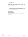
1 Introduction
1.1 General
The ACS400 software package is a convenient tool designed for visualizing, storing
and transmitting all data delivered by advanced microprocessor-based burner controls
made by Siemens HVAC Products.
The ACS400 operating software provides the following operating functions:
•
•
•
Reading the burner control’s operating states and types of errors that can occur
Data logging (logging, triggering and presenting the data delivered by the burner
control)
Printing functions for producing documentation
All key data can be saved in files and retrieved at a later time, even without having the
burner control connected.
Operation of the program is primarily based on Windows standards and requires basic
knowledge of software programs.
!
This document was issued on December 12, 2003, and covers ACS400 software version 2.1.7 or higher.
4/39
Siemens Building Technologies
HVAC Products
PC Software for microprocessor-based Burner Controls
1 Introduction
CC1J7350en
22.01.2004
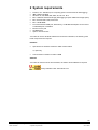
2 System requirements
•
•
•
•
•
•
•
•
•
•
Pentium, min. 350 MHz (more computing power recommended for data logging)
IBM or IBM-compatible
Windows 95, 98, 98SE, ME, 2000, XP, NT min. SP 3
Min. 10 MB free hard disk storage (data logging requires additional storage space)
Min. resolution 800 x 600, 256 colors
Min. 128 MB RAM
Free serial RS-232 COM port; alternatively, a USB RS-232 adapter can be used if
a USB COM port is available.
Mouse or touch pad
CD-ROM drive
Option: Internet access
To be able to use the ACS400 software and online documentation, the following additional components are required:
Hardware
•
Opto-electronic interface OCI400 for UDS communication
or, optionally,
•
Communication interface for eBus or BSB
Software
To be able to read the online documentation, the Adobe Acrobat Reader is required.
Freely available under: www.adobe.com
5/39
Siemens Building Technologies
HVAC Products
PC Software for microprocessor-based Burner Controls
2 System requirements
CC1J7350en
22.01.2004
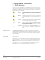
3 Typographical conventions
3.1 Safety guidelines
This manual contains notices which you should observe to ensure your own personal
safety, as well as to protect the product and connected equipment. These notices are
highlighted in the manual by a warning triangle, arrow or hand and are marked as follows according to the level of danger:
Danger
indicates that death, severe personal injury or substantial
property damage will result if proper precautions are not
taken.
Warning
indicates that death, severe personal injury or substantial
property damage can result if proper precautions are not
taken.
Caution
indicates that minor personal injury or property damage
can result if proper precautions are not taken.
!
Note
draws your attention to particularly important information on the product, handling the product, or to a particular part of the documentation.
"
Reference
makes reference to additional information given in
other pieces of user documentation, chapters or sections.
Qualified personnel
Only qualified personnel should be allowed to install and work on this equipment.
Qualified persons are defined as persons who are authorized to commission, to ground,
and to tag circuits, equipment, and systems in accordance with established safety practices and standards.
Correct usage
Note the following:
This device and its components may only be used for the applications described in the
technical documentation, and only in connection with devices or components from other
manufacturers which have been approved or recommended by Siemens HVAC Products.
This product can only function correctly and safely if it is transported, stored, set up,
and installed correctly, and operated and maintained as recommended.
6/39
Siemens Building Technologies
HVAC Products
PC Software for microprocessor-based Burner Controls
3 Typographical conventions
CC1J7350en
22.01.2004
4 License and liability regulations
!
ENDUSER LICENSE AGREEMENT FOR ACS400 SOFTWARE
IMPORTANT – PLEASE READ CAREFULLY!
The present Enduser License Agreement (hereinafter referred to as LICENSE
AGREEMENT) is a legally binding agreement between you (as a natural or legal entity)
and Landis & Staefa Produktion GmbH, a Siemens company (hereinafter referred to as
L&S), covering the above mentioned software, which includes computer software and,
potentially, associated media, printed material and documentation in online or electronic format (hereinafter referred to as SOFTWARE). Use of the SOFTWARE is governed by the terms of this LICENSE AGREEMENT which is enclosed with the SOFTWARE or constitutes part of it. Use of the SOFTWARE is only permitted in connection
with a LICENSE AGREEMENT, which cannot be transferred to thirds. By installing,
copying, downloading, otherwise using or accessing the SOFTWARE, you agree to
comply with the terms of this LICENSE AGREEMENT. If you do not agree with the requirements of the LICENSE AGREEMENT, you will not be authorized to install or run
the SOFTWARE.
The SOFTWARE is protected by copyrights and international copyright agreements as
well as other copyright contracts and laws and agreements covering the intellectual
property of L&S. The SOFTWARE is made available under license and is not for sale.
1.
LICENCE RIGHTS
This LICENSE AGREEMENT will grant you the following rights:
By purchasing the license, the licensee is granted the non-transferable, non-exclusive
right to install the software package on a computer system and to use it. The number of
users operating the SOFTWARE simultaneously shall be limited by the number of licenses purchased. Reproduction / multiplication and sale of the SOFTWARE without
L&S’ consent in writing are expressly forbidden. Use of all updates, language versions,
module extensions, etc., provided via the Internet or made available on data carriers,
which are to be regarded as extensions or supplements to this SOFTWARE and requiring the complete installation of this SOFTWARE, is also governed by the terms of this
LICENSE AGREEMENT.
Reserve of rights: L&S reserves all rights that are not specifically granted.
2. DESCRIPTION OF OTHER RIGHTS AND RESTIRCTIONS
Restrictions in terms of reverse engineering, decompilation and disassembly: You shall
not be authorized to reverse engineer, decompile or disassemble the SOFTWARE,
unless expressly permitted by applicable law, regardless of this restriction.
Marks: This LICENSE AGREEMENT does not grant you any rights in connection with
marks or service marks from L&S.
Support services: L&S may offer you support services in connection with the SOFTWARE. Such support services can be used in accordance with L&S’ directives and
programs as described in the User Manual, the documentation in online format and / or
other materials provided by L&S. Any supplementary software code made available to
you as part of the support services is regarded as part of the SOFTWARE and is governed by the terms of this LICENSE AGREEMENT. L&S shall be authorized to make
use of the technical data provided by you to L&G as part of the support services, for
business purposes inclusive of product support and product development. L&S commits itself to use such technical data only anonymously.
Notice of termination: L&S shall be entitled to terminate the LICENSE AGREEMENT, if
you violate it, irrespective of other rights. In such a case, you commit yourself to destroy
all copies of the SOFTWARE and all associated components.
7/39
Siemens Building Technologies
HVAC Products
PC Software for microprocessor-based Burner Controls
4 License and liability regulations
CC1J7350en
22.01.2004
3. COPYRIGHT
L&S or its suppliers is / are the owner(s) and copyright owner of the SOFTWARE (inclusive of but not limited to illustrations, photographs, animations, videos, audios, music, text und "applets" contained in the SOFTWARE), the printed accompanying materials and every copy of the SOFTWARE. All rights and intellectual property rights of contents accessible with the help of the SOFTWARE are the property of the respective
contents owner and may be protected by applicable copyright laws and other laws and
agreements on intellectual property. This LICENSE AGREEMENT does not give you
any rights to use such contents. If this SOFTWARE contains documentation that is provided in electronic form only, you shall be allowed to print it.
4. BACKUP COPY
After installation of a copy of the SOFTWARE in compliance with the terms of this LICENSE AGREEMENT, you may keep the original medium on which L&S supplied the
SOFTWARE for backup or archiving purposes only. If the original medium is required
for running the SOFTWARE on the computer, you may produce a copy of the SOFTWARE for backup or archiving purposes only. You may under no circumstances produce copies of the SOFTWARE or of printed materials enclosed with the SOFTWARE
unless explicitly permitted under the terms of this LICENSE AGREEMENT.
5. LIMITED LIABILITY
You recognize that the SOFTWARE is licensed with the exclusion of any liability or warranty. Neither L&S, nor its mother company nor their licensors warrant, expressly or
implicitly, that the SOFTWARE is suited for a particular purpose or that no property
rights, copyrights, trademark rights, or other rights of thirds, will be violated.
In particular, no warranty is given that the SOFTWARE will provide certain functionalities, or meet specific requirements, or operate flawlessly. Any information provided by
or on behalf of L&S does not represent any liability under the terms of this LICENSE
AGREEMENT. You will take full responsibility for installing and using the SOFTWARE.
Caution
6. SPECIAL NOTE
In cases where the SOFTWARE can be or is used for setting the parameters of
combustion plant, the licensee and any user will assume special responsibility.
After parameterization, both the licensee and the user are committed to verify the
safe functioning of the plant and to ensure manual shutdown, if required. The licensee, the OEM, or the user who made the settings will always take full responsibility for the parameters, their settings and compliance with the relevant national and international standards and safety regulations. The safety notes given
in the respective documentation must be strictly observed. L&S and its suppliers
and other group companies of Siemens AG will not assume any liability for special or indirect damage, consequential damage, other damage, or damage resulting from incorrect parameter settings.
7. LIMITATION OF LIABILITY
In each and every case, L&S, its staff members, other group companies of Siemens
AG, licensors and suppliers cannot be held liable for the procurement of spare parts,
damage to property, lost profits, loss of data for direct or indirect damage of any kind.
Liability for damage resulting from the usage or non-usage of the SOFTWARE, if the licensee or thirds informed L&S about the possibility of damage, shall also be excluded.
This also includes damage caused by viruses. This does not apply to situations where,
in accordance with product liability law, or in cases of intent, liability is mandatory.
8/39
Siemens Building Technologies
HVAC Products
PC Software for microprocessor-based Burner Controls
4 License and liability regulations
CC1J7350en
22.01.2004
8. RECTIFICATION OF FAULTS / TECHNICAL SUPPORT
The licensee cannot call on L&S, its staff members, other group companies of Siemens
AG, licensors or suppliers for rectification of faults or other technical support. L&S reserves the right to improve the SOFTWARE governed by this LICENSE AGREEMENT,
or to make changes to it without prior notice.
9. APPLICABLE LAW AND JURISDICTION
This LICENSE AGREEMENT shall be governed by German law excluding any collision
law. Place of jurisdiction shall be Rastatt, Germany, if the licensee is a businessman.
© Landis & Staefa Produktion GmbH (a Siemens company) 2002
9/39
Siemens Building Technologies
HVAC Products
PC Software for microprocessor-based Burner Controls
4 License and liability regulations
CC1J7350en
22.01.2004
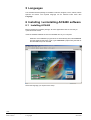
5 Languages
The ACS400 software package is available in German, English, French, Italian, Danish
Spanish and Dutch. The required language can be selected under menu item
Language.
6 Installing / uninstalling ACS400 software
6.1 Installing ACS400
Before installing the software package, all active applications that are not really required should be closed.
Insert the ACS400 software CD into the CD-ROM drive of your computer.
Windows: If the installation program does not automatically start, select Execute
from the Windows start menu. Then, type d:\start.htm (replace d by the letter of
the CD-ROM drive) and click OK.
Select the language you require for the setup.
10/39
Siemens Building Technologies
HVAC Products
PC Software for microprocessor-based Burner Controls
5 Languages
CC1J7350en
22.01.2004
Cont´d
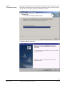
6.1 Installing ACS400
Next, select the option for the direct execution of the program file without saving the file.
Depending on the settings made and the type of operating system, a warning note may
appear. Confirm with Yes to display the "InstallShield" window.
Follow the Installation Instructions.
11/39
Siemens Building Technologies
HVAC Products
PC Software for microprocessor-based Burner Controls
6 Installing / uninstalling ACS400 software
CC1J7350en
22.01.2004
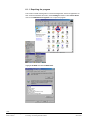
6.1.1 Repairing the program
This function installs missing files or corrects damaged files, links and registration entries. From the Windows start menu, select Settings and then under Control Panel
click on the Add/Remove Programs icon to open the program.
Highlight ACS400 and select Add/Remove.
12/39
Siemens Building Technologies
HVAC Products
PC Software for microprocessor-based Burner Controls
6 Installing / uninstalling ACS400 software
CC1J7350en
22.01.2004
Cont`d
6.1.1 Repairing the program
Follow the instructions of “InstallShield”.
6.2 Uninstalling ACS400
From the Windows start menu, select Programs – ACS – Uninstall ACS400.
13/39
Siemens Building Technologies
HVAC Products
PC Software for microprocessor-based Burner Controls
6 Installing / uninstalling ACS400 software
CC1J7350en
22.01.2004
6.3 Files contained in the scope of delivery
The software CD contains the files in a condensed form. These are unpacked during
installation and filed on the destination drive in the selected directory.
The following files are required and installed for running the ACS400:
Installation directory:
ACS.exe
Windows system directory:
-
PropertyWindow5.ocx
ScrollBarFix.ocx
SplitterControl.ocx
ssa3d30.ocx
ssdw3b32.ocx
ssmedt32.dll
sspng2.dll
ssprn32.dll
sssplt30.ocx
sstbars.ocx
Sstran30.ocx
unzip32.dll
Asycfilt.dll
Cmdlgde.dll
Comcat.dll
Comdlg32.ocx
flxgdde.dll
mfc42.dll
mscc2de.dll
mscmcde.dll
mscomct2.ocx
mscomctl.ocx
mscomde.dll
mscomm32.ocx
msflxgrd.ocx
msmapi32.ocx
msmpide.dll
msvbvm60.dll
msvcrt.dll
oleaut32.dll
olepro32.dll
stdole2.tlb
tabctde.dll
tabctl32.ocx
Vb6de.dll
14/39
Siemens Building Technologies
HVAC Products
PC Software for microprocessor-based Burner Controls
6 Installing / uninstalling ACS400 software
CC1J7350en
22.01.2004
6.4 Generated files
When ACS400 is started for the first time, a data directory will be generated below the
ACS400 program directory (C:\Program Files\ACS400).
7 Handling and storage
!
7.1 Handling the CD
•
•
•
•
Do not expose the CD to direct solar radiation or other UVA / UVB radiation
Avoid excessive temperatures, humidity, dust, shocks, dirt, scratches, etc.
Clean the CD only with a suitable cleansing agent using a dry, soft and flufffree cloth
If not is use, keep the CD in the plastic box
8 Hardware installation / deinstallation
8.1 Warning notes
Danger
•
•
•
Before performing any wiring changes in the connection area, completely isolate
the equipment from the mains supply (all-polar disconnection)
Take appropriate measures to provide protection against electrical shock hazard
Press the burner control´s reset button / operating button manually (applying a
force of no more than 10 N), without using any tools or pointed objects
15/39
Siemens Building Technologies
HVAC Products
PC Software for microprocessor-based Burner Controls
7 Handling and storage
CC1J7350en
22.01.2004
8.2 Mounting notes
!
Ensure that the relevant national safety regulations are complied with.
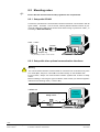
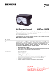
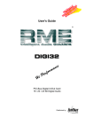
8.2.1 Setup with OCI400
Connect the optoelectronic communication interface OCI400 for communication with all
types of LMO… and LMG… burner controls, made by Siemens HVAC Products, to your
computer’s RS-232 (COM) port as shown below without using any extension cable ( "
according to Data Sheet N7614).
ACS400
PC software
LMO... / LMG...
OCI400
Adapter ring
only necessary for LMG... burner controls
7350z02en/0104
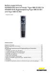
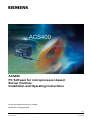
8.2.2 Setup with other optional communication interfaces
Warning
The communication interface must be suited for use with burner controls that only have
TTL levels (RxD, TxD) as a “4-wire eBus connection facility“ on the hardware side.
For this reason, always use communication interface systems that conform to safety
class II.
Before installing or removing this type of interface, make certain you read the supplier’s
instructions and warning notes (" refer to 8.1).
LMO82.100
ACS400
Communication Interface System
Safety class II
Plug
Cable
Cable
PC software
Plug
7350z01en/0104
16/39
Siemens Building Technologies
HVAC Products
PC Software for microprocessor-based Burner Controls
8 Hardware installation / deinstallation
CC1J7350en
22.01.2004
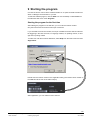
9 Starting the program
Connect the burner control via the OCI400 interface or an optional interface module for
eBus or LPB light communication to your PC.
To start the software program, click the ACS icon on the Desktop or select ACS from
the Windows start menu under Programs.
Starting the program for the first time
After starting the program for the first time, you can enter the license number.
Only then will the tool work with its full scope of functions.
If you work without a license number, the scope of software functions will be restricted:
No triggering in the case of events, no language variants, no updating choices, no storage and no printing of data.
To make use of all the functions afterwards, select Help from the start screen and then
Registration.
Please enter the license number in the registration field (you find the license number on
the ASN label at the rear of the CD envelope).
After registration, you can make full use of the tool.
17/39
Siemens Building Technologies
HVAC Products
PC Software for microprocessor-based Burner Controls
9 Starting the program
CC1J7350en
22.01.2004
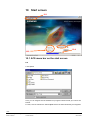
10 Start screen
10.1
10.3
10.4
10.2
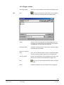
10.1 ACS menu bar on the start screen
File
Load Update
Here, you can integrate into the ACS400 new program extensions that you receive as a
ZIP file.
For that, click the relevant file. Select Open and the file will automatically be integrated.
18/39
Siemens Building Technologies
HVAC Products
PC Software for microprocessor-based Burner Controls
10 Start screen
CC1J7350en
22.01.2004
Cont‘d
10.1 ACS menu bar
on the start screen
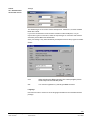
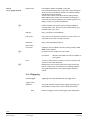
Settings
The standard type of connection used is UDS protocol. COM Port 1, and the standard
Baud rate is 9600.
If you have connected the communication modules to other COM ports, or if you
require other types of connection, select the required type of connection and start the
automatic port and Baud rate identification.
Save your settings. They will automatically be adopted next time the program is started.
Printer
Print
When selecting the Print command, the current program picture
will be output on the selected printer.
Exit
You close the application by selecting the Exit command.
Language
Use this menu item to select one of the languages available for the ACS400 software
package.
19/39
Siemens Building Technologies
HVAC Products
PC Software for microprocessor-based Burner Controls
10 Start screen
CC1J7350en
22.01.2004
Cont‘d
10.1 ACS menu bar
on the start screen
Help
Registration
Possibility of software registration (license number required).
Info
Information about the ACS400 software package (version number,
Internet page for update) and your PC system.
Help
Opening the online documentation on the ACS400 (Acrobat Reader
required).
10.2 State
Receive data
When this menu item is selected, you can use the pop-up menu to choose from different communication reports (" refer to 10.3).
Load data / offline
Display and evaluation of recorded files or files that you have received via e-mail or
data logging, for example. The data must conform to the ACS400 format. Connection to the burner control is not required.
Demo mode / offline
Display of a demo file. Connection to the burner control is not required.
10.3 Popup menu for type of connection
Choice of connections:
-
-
-
UDS with OCI400 (optical interface)
for all types of LMO… burner controls.
Sampling rate for trouble-free communication: Typically 150 ms, max. 170 ms
eBus with interface
for burner controls of the LMO… family with eBus. In the case, an adapter for connecting the eBus interface to the RS-232 PC interface is required.
Sampling rate for trouble-free communication: Typically 1 s, max. 2 s depending on
the data sequence.
LMG protocol with OCI400 (optical interface)
for all types of LMG… burner controls. Data can only be delivered in the fault status
position after requesting the blink code.
Sampling rate for trouble-free communication: Typically 1 s, max. 1.2 s
10.4 State of connection
The connection shows you if there is communication with a burner control, or it shows
the state of the connection. The bar moves until the type of burner control is identified.
If the connection was successfully opened, the application of the relevant burner control
will be indicated.
20/39
Siemens Building Technologies
HVAC Products
PC Software for microprocessor-based Burner Controls
10 Start screen
CC1J7350en
22.01.2004
11 Application screen
This screen is dynamic and will be displayed in accordance with the identified application of the burner control.
The relevant outputs / inputs are displayed by highlighted symbols.
11.1
11.2
11.6
11.3
11.4
11.5
11.1 ACS menu bar on the application screen
File
(" refer to 10.1)
Language
(" refer to 10.1)
View
Here, you can change between the application screen and the data
logger view.
Help
(" refer to 10.1)
11.2 Identification of type of burner control
“The normal type” reference of the detected type of burner control will be shown
here.
21/39
Siemens Building Technologies
HVAC Products
PC Software for microprocessor-based Burner Controls
11 Application screen
CC1J7350en
22.01.2004
11.3 Info table
The info table contains all specific data that the identified type of burner control
transmits to the program.
11.4 Error code table
The last 5 or 10 errors (depending on the type of burner control) from the burner control’s error storage will be read out and displayed.
11.5 Flame signal / mains voltage graph
This display shows the flame current and the mains voltage as an analog value over
the last 10 seconds.
You can enlarge or reduce the presentation with the relevant button and also stop it for
a short moment to have a closer look at it.
Flame current and mains voltage display are stopped, but data are still
transmitted in the background
Flame current and mains voltage are continued to be displayed
Laying a grid on the display.
Enlarging the display
Reducing the display
11.6 State
Shows you the current mode of the program.
Choice of modes:
-
Receive data UDS with OCI400
Receive data eBus with interface
Receive data LMG... protocol with OCI400
Load data / offline
Demo mode / offline
22/39
Siemens Building Technologies
HVAC Products
PC Software for microprocessor-based Burner Controls
11 Application screen
CC1J7350en
22.01.2004
11.7 Flame indication
Flame current is indicated in µA.
The indication is proportional to the flame signal and is system
specific.
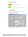
12 Data logger
Selection (" also refer to 11.1 View) between application screen and data logger view.
12.1 Register card “Trigger”
12.1.1
12.1.2
12.1.3
This function is used to log burner control data with selected events.
23/39
Siemens Building Technologies
HVAC Products
PC Software for microprocessor-based Burner Controls
12 Data logger
CC1J7350en
22.01.2004
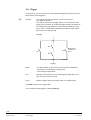
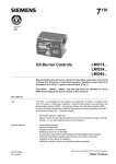
12.1.1 Trigger
On this picture, you can select one or several interlinked trigger events with which different actions can be triggered.
!
Operator:
If you select several trigger events, you can link them by a
logic AND or logic OR
If you define more than one trigger signal, you can interconnect the
signals via the operator. The individual trigger events must always be
connected with a logic AND (both criteria must be satisfied) or logic
OR (1 of the 2 criteria must be satisfied). Note that the logic AND is
given priority over the logic OR.
Example:
BV1
Alarm
GM
= GM OR BV1
AND BV2 OR
Alarm
BV2
7350z03en/0104
Triggering
Event:
- No data reception (in the event of a communication breakdown)
- Exceeding or undershooting of analog value
- Level change of digital value
Port:
Selection of all relevant input and output signals (depending on the
type of burner control and event)
Value:
Display of trigger values (any analog value or 0/1 digital value)
Click Add to include in the trigger table.
You can delete the set triggers by selecting Remove.
24/39
Siemens Building Technologies
HVAC Products
PC Software for microprocessor-based Burner Controls
12 Data logger
CC1J7350en
22.01.2004
12.1.2 Trigger actions
!
Recording the file:
The burner control’s data are saved when indicating the path.
File:
Create your own directory here where you would like to
save the data. Do not save any files in the Demo folder.
Notes:
Field for entering text that shall be saved together with your
recording. By entering text, it will be easier for you to identify
and administer your recordings at a later data.
Recording range:
Indication of required period of time before or after the trigger
event that shall be recorded.
Number of events to
save:
Here, you can indicate whether, based on subsequent trigger
events, a recording shall be started once or several times.
Call up program:
Here too, the file Browser can be opened and every file (.exe)
that can be executed can be started with a trigger event.
File:
Here, you can open the path where the required program
file is filed.
Delay:
Indication of delay time for the program call to be triggered.
25/39
Siemens Building Technologies
HVAC Products
PC Software for microprocessor-based Burner Controls
12 Data logger
CC1J7350en
22.01.2004
Cont’d
12.1.2 Trigger actions
Send E-mail:
!
Preconditions: MAPI-compatible e-mail client
such as Outlook Express 5.0 (component of Internet Explorer
5.0 and running under Win98, WinNT 4.0, Win2000, WinMe,
and WinXP) must be installed!
Access to the Internet via a data network; analog modem;
GSM; ISDN or DSL modem and a provider that supports email functions must be installed in your operating system. For
details, contact your system administrator.
Please note that use of this function generates additional
communication costs. Also check your modem settings (e.g.
shutdown when not in use).
Address:
Entry of recipient’s e-mail address.
User name:
User name of your selected connection or name of user in email profile in the case of a LAN connection.
Password:
Entry of the associated password.
Open dialup
connection:
!
Sending e-mail via a DFÜ connection (analog modem, GSM,
ISDN or DSL modem).
Do not dial in case a LAN connection exists.
Connection:
Test:
Selection of all DFÜ connections available on
your system.
You can use this button to check your e-mail connection and
send an e-mail at the same time.
Data from the burner control cannot be received during the
time an e-mail is sent. The relevant error message appears
during that period of time. Then, data reception will be resumed.
!
12.1.3 Triggering
Activate trigger:
Trigger active
indication:
after:
Triggering will be activated with the next trigger event.
This green indication appears when triggering is being processed. Data from the burner control can still be received.
Number of trigger events until the trigger action takes place.
26/39
Siemens Building Technologies
HVAC Products
PC Software for microprocessor-based Burner Controls
12 Data logger
CC1J7350en
22.01.2004
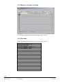
12.2 Register card “Data Stream”
12.2.1
12.2.2
This screen shows you the data stream delivers to the PC by the burner control.
12.2.1 Function “Replay / Pause”
Data stream display is stopped, whereby the data continue to be transmitted
in the background.
Data stream display is continued from the current point in time.
12.2.2 Logging the data stream
!
Create your own directory here where you would like to save the data. Do
not save any files in the Demo folder. (" also refer to 12.1.2 Recording the
file).
Start logging.
Stop logging.
27/39
Siemens Building Technologies
HVAC Products
PC Software for microprocessor-based Burner Controls
12 Data logger
CC1J7350en
22.01.2004
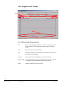
12.3 Register card “Graph”
12.3.1
12.3.2
12.3.3
12.3.4
12.3.1 Selecting the displayed data
Port:
Burner control-dependent selection of all input or output signals, such
as flame signal or mains voltage that can be shown on the graph
screen.
Color:
Selection of color for the chosen port.
Add:
Adding the selected port to the display. A maximum of 10 input or output values can be displayed.
Remove:
Removing a port from the display (" also refer to 12.3.2).
Display range:
Indication of the required scope of display on the time axis. The maximum display range comprises 86,400 seconds (24 hours).
Adopt:
Adoption of display range by the graph.
28/39
Siemens Building Technologies
HVAC Products
PC Software for microprocessor-based Burner Controls
12 Data logger
CC1J7350en
22.01.2004
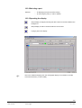
12.3.2 Selecting a port
Selection
- ... for displaying the ports and their scaling.
- ... for removing the ports (" refer to 12.3.1).
12.3.3 Operating the display
Graph display is stopped, whereby the data continue to be transmitted in the
background.
Graph display of data is continued with the current value.
Laying a grid on the display.
!
Due to the software sampling rate, the oscillograph display is not suited for accurate
time measurements (" refer to 10.3).
29/39
Siemens Building Technologies
HVAC Products
PC Software for microprocessor-based Burner Controls
12 Data logger
CC1J7350en
22.01.2004
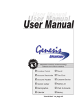
12.3.4 Display of a trigger recording
The vertical line indicates the point in time the trigger event occurred.
12.3.5 Port table
Legend of selectable ports (depending on the type of burner control):
I Flame signal ION (analog) ± 5 %
I Flame signal ION (digital)
I Flame signal QRB/QRC (analog) ± 5 %
I Flame signal QRB/QRC (digital)
I Mains voltage (analog) ± 5 %
I Mains voltage (digital)
I Oil preheater temperature (analog) ± 5 %
I Oil preheater temperature (digital)
I Fan motor
I Ignition
I SBV
I BV1
I BV2
I BVZ
I Oil preheater
I BV3
I Pump
I Flue gas supervision
I Release contact of oil preheater
I Air damper actuator
30/39
Siemens Building Technologies
HVAC Products
PC Software for microprocessor-based Burner Controls
12 Data logger
CC1J7350en
22.01.2004
Cont’d
12.3.5 Port table
I Reset
I Remote reset
I LP
I GP
I Thermostat
I Load control
I Fuel selection
I Actuator cam position ZU
I Actuator cam position KL
I Actuator cam position ZL
I Actuator cam position BV2
I Actuator cam position GL
I Flow switch
I STB
I Summer / winter switch
O Alarm lamp
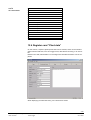
12.4 Register card “Plant data”
On this screen, if required, plant-specific data can be entered, which can be saved together with the data sets, such as a trigger event, data stream recording, or an info table.
Based on the data, administration of recordings with collected information can be simplified.
When displaying recorded data sets, your entries will be shown.
31/39
Siemens Building Technologies
HVAC Products
PC Software for microprocessor-based Burner Controls
12 Data logger
CC1J7350en
22.01.2004
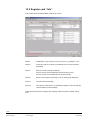
12.5 Register card “Info”
This screen shows all relevant data of the burner control.
Block 1:
Identification / type reference of burner control, e.g. LMO24.111.A2.
Block 2:
Production date and number, provided the burner control transmits
these data.
Block 4:
Start up counter: Number of startups
Service counter actual: Reading since the last service visit
Service counter set: Possible service counter intervals
Block 8:
Burner control-specific parameter, such as waiting and safety time.
Block 9:
Current lockout information.
Block 10:
Fault history of the last 5 or 10 fault status signals in clear text with the
relevant startup counter readings.
When all blocks have been updated, the message “Data have been updated“ will appear.
32/39
Siemens Building Technologies
HVAC Products
PC Software for microprocessor-based Burner Controls
12 Data logger
CC1J7350en
22.01.2004
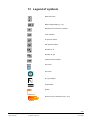
13 Legend of symbols
Mains ON / OFF
Mains voltage display (± 5 %)
Demand for heat from the controller
Load controller
Air pressure switch
Gas pressure switch
Actuator for air
Actuator for gas
Closed Position Indicator
Fuel valve
Fan motor
Air / gas damper
Oil preheater
Ignition
Flame current is indicated in µA (± 5 %)
33/39
Siemens Building Technologies
HVAC Products
PC Software for microprocessor-based Burner Controls
13 Legend of symbols
CC1J7350en
22.01.2004
The indication is proportional to the flame
signal and is system specific.
Signal lamp input / output on (active)
Alarm / warning lamp
Flame bar with indication of flame current
(± 5 %)
Display of data is stopped, whereby the
data continue to be transmitted in the
background
Display of data is continued
File is opened
File is saved
Start data logging
Stop data logging
Display of grid
Safety class II 1)
1)
Communication interface systems that offer safety class II are systems, where protection against electric shock hazard is ensured not only by the basic insulation, but
also by additional protective measures,
such as double or reinforced insulation.
34/39
Siemens Building Technologies
HVAC Products
PC Software for microprocessor-based Burner Controls
13 Legend of symbols
CC1J7350en
22.01.2004
14 Glossary
BSB
Boiler System Bus
DFÜ
Datenfernübertragung – data exchange via the Telefone line (Internet)
over long distances
Data logger
Program section used for displaying and recording the burner control´s
activities
DSL
Digital Subscriber Line
eBus
Serial 2-wire bus for communication between heating system devices
GSM
Global System for Mobile Communications
ISDN
Integrated Services Digital Network
LAN
Local Area Network
LMG
Modern, microprocessor-based burner control made by Siemens HVAC
Products for use with gas burner
LMO
Modern, microprocessor-based burner control made by Siemens HVAC
Products
MAPI
Messaging Application Programming Interface – defined interface used
for sending e-mails from the Windows software
OCI400
Optoelectronic interface module used for communication with all types
of LMO… and LMG… burner controls made by Siemens HVAC Products
UDS
Undirektionale Schnittstelle - unidirectional interface
USB
Universal Serial Bus
35/39
Siemens Building Technologies
HVAC Products
PC Software for microprocessor-based Burner Controls
14 Glossary
CC1J7350en
22.01.2004
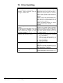
15 Error handling
Error
The display bars fort he connection state
do not change when receiving data.
Message: “Check connection“ and “Receiving no readable data“.
The following Windows error message
appears:
”ACS400.exe has generated errors and
will be closed by Windows. You will
need to restart the program. An error
log is being created.”
Automatic interface identification cannot
identify the type of burner control.
Display of oscillograph stops from time to
time
Data reception and saving is impaired or
faulty
Troubleshooting
Check to see whether the correct type of
connection has been selected (" refer to
10.3 Popup menu for type of connection).
Check if the burner control is in communication mode (" refer to the documentation of the relevant burner control or
burner).
Check to see if the communication interface has been correctly connected ("
also refer to the documentation of the
communication interface).
Check the interface settings (" refer to
10.1 ACS menu bar on the start
screen).
To ensure trouble-free operation of the
program, the computer must be restarted.
If this is not observed, data recording may
stop next time the program is started or
the ”Close window“ function will not be
correctly performed.
1. Check to see if the communication
module is connected to the computer
(e.g. 1 for COM 1).
2. From the “File / Settings“ menu, select the COM port required by you
(e.g. 1 for COM 1).
3. Save your settings.
4. Start data reception.
Data logging requires more processing
capacity!
Reduce the number of graphs to be displayed or close the parallel running software applications not required.
Check to see if a virus scanner is active.
If yes, deactivate it. Do not use ACS400
simultaneously with a virus scanner!
36/39
Siemens Building Technologies
HVAC Products
PC Software for microprocessor-based Burner Controls
15 Error handling
CC1J7350en
22.01.2004
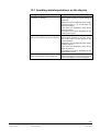
15.1 Avoiding misinterpretations on the display
Display
Digital flame signal “1“ on the oscillograph
on startup or shutdown
Digital flame signal “1“ on the oscillograph
when burner control has gone to lockout
Extensive ramp response and decay
times of the signals in the oscillograph
Interpretation
Certain types of burner control perform a
flame signal amplifier test after startup or
shutdown.
Response: The oscillograph shows a digital flame signal “1“ for a short time (for
about 2 seconds).
This does not necessarily mean that a
flame is present.
The flame can only be assessed via the
analog flame signal.
With certain types of burner control, the
flame signal amplifier is set more sensitive in the event of power failures in the
lockout position.
Response: The oscillograph shows a digital flame signal “1“.
This does not necessarily mean that a
flame is present.
The flame can only be assessed via the
analog flame signal.
During the communication pauses, the
points sampled are connected. The actual
value of the signal cannot be displayed
37/39
Siemens Building Technologies
HVAC Products
PC Software for microprocessor-based Burner Controls
15 Error handling
CC1J7350en
22.01.2004
16 Index
A
Application screen .....................................................21
ACS menu bar .....................................................21
Error code table ...................................................22
Flame indication...................................................23
Flame signal / mains voltage graph .....................22
Identification of type of burner control..................21
Info table ..............................................................22
State.....................................................................22
D
Data logger................................................................23
Register card `Data stream´.................................27
Function `Replay / Pause´..................................27
Logging the data stream ....................................27
Register card `Graph´ ..........................................28
Display of a trigger recording .............................30
Operating the display .........................................29
Port table............................................................30
Selecting a port ..................................................29
Selecting the displayed data ..............................28
Register card `Info´ ..............................................32
Register card `Trigger´.........................................23
Trigger................................................................24
Trigger actions ...................................................25
Triggering ...........................................................26
Registercard `Plant data´ .....................................31
E
Error handling............................................................36
Avoiding misinterpretations on the display...........37
G
Glossary ....................................................................35
H
Handling and storage ............................................... 15
Hardware installation / deinstallation ........................ 15
Mounting notes.................................................... 16
Setup with OCI400 ............................................ 16
Setup with other optional communication
interfaces ....................................................... 16
Warning notes ..................................................... 15
I
Installing / uninstalling ACS400 software
Files contained in the scope of delivery .............. 14
Generated files.................................................... 15
Installing .............................................................. 10
Repairing the program ........................................ 12
Uninstalling.......................................................... 13
L
Languages................................................................ 10
Legend of symbols ................................................... 33
License and liability regulations.................................. 7
S
Start screen .............................................................. 18
ACS menu bar..................................................... 18
Popup menu for type of connection .................... 20
State.................................................................... 20
State of connection ............................................. 20
Starting the program................................................. 17
For the first time .................................................. 17
System requirements.................................................. 5
T
Typographical conventions
Safety guidelines................................................... 6
38/39
Siemens Building Technologies
HVAC Products
PC Software for microprocessor based Burner Controls
16 Index
CC1J7350en
22.01.2004
Siemens Building Technologies
Landis & Staefa Produktion GmbH
Berliner Ring 23
76437 Rastatt
Tel:
+49 7222 598 0
Fax:
+49 7222 53182
www.landisstaefa.com/rastatt
© 2003 Siemens Building Technologies
Änderungen vorbehalten
39/39
Siemens Building Technologies
HVAC Products
PC Software for microprocessor based Burner Controls
CC1J7350en
22.01.2004