1
Elisys Quattro
| User Manual
HUMAN ELISYS QUATTRO
User Manual
|
Cat.No. 16300/1
Edition:
Rev. /DATE.
REVISION DESCRIPTION
01/2004-12
First edition
02/2011-01
Update cover and back page
System
Manufacturer:
HUMAN Gesellschaft für Biochemica und Diagnostica mbH
Software-copyrights
The ELISYS QUATTRO software is the intellectual property of HUMAN GmbH.
Intellectual property rights shall remain with HUMAN GmbH
You are entitled to use the ELISYS QUATTRO software and the printed accompanying material at your place of work only.
Any violations of property rights or copyright or trademark may be subject to legal
action.
Copyright © 2010, HUMAN GmbH. All rights reserved.
HUMAN Gesellschaft für Biochemica und Diagnostica mbH
Max-Planck-Ring 21
D-65205 Wiesbaden, GERMANY
Neither this manual nor any parts of it may be duplicated or transmitted in any way without the written
approval of HUMAN GmbH.
Table of Contents
1
Intended Use . . . . . . . . . . . . . . . . . . . . . . . . . . . . . . . . . . . . 1-1
1.1
Typographical Conventions . . . . . . . . . . . . . . . . . . . . . . . . . . . . .
1.1.1 Warning Messages . . . . . . . . . . . . . . . . . . . . . . . . . . . . . . . . . . .
1.1.2 Notes . . . . . . . . . . . . . . . . . . . . . . . . . . . . . . . . . . . . . . . . . . . . .
1.1.3 Symbol Keys. . . . . . . . . . . . . . . . . . . . . . . . . . . . . . . . . . . . . . . .
1.1.4 Special Types . . . . . . . . . . . . . . . . . . . . . . . . . . . . . . . . . . . . . . .
1.2 Safety Instructions. . . . . . . . . . . . . . . . . . . . . . . . . . . . . . . . . . . . .
1.2.1 General Safety . . . . . . . . . . . . . . . . . . . . . . . . . . . . . . . . . . . . . .
1.2.2 Electrical Safety . . . . . . . . . . . . . . . . . . . . . . . . . . . . . . . . . . . . .
1.2.3 Laser Safety . . . . . . . . . . . . . . . . . . . . . . . . . . . . . . . . . . . . . . . .
1.2.4 Mechanical Safety . . . . . . . . . . . . . . . . . . . . . . . . . . . . . . . . . . .
1.2.5 Biological Safety . . . . . . . . . . . . . . . . . . . . . . . . . . . . . . . . . . . . .
1.2.6 Cleaning the System. . . . . . . . . . . . . . . . . . . . . . . . . . . . . . . . . .
1.2.7 Disposal . . . . . . . . . . . . . . . . . . . . . . . . . . . . . . . . . . . . . . . . . . .
1.3 Positions of Safety Labels and Type Label . . . . . . . . . . . . . . . . .
1.3.1 General Warning Labels . . . . . . . . . . . . . . . . . . . . . . . . . . . . . . .
1.3.2 Biological Hazard Labels . . . . . . . . . . . . . . . . . . . . . . . . . . . . . .
1.3.3 Electrical Hazard Labels . . . . . . . . . . . . . . . . . . . . . . . . . . . . . . .
1.3.4 Laser Hazard Labels. . . . . . . . . . . . . . . . . . . . . . . . . . . . . . . . . .
1.3.5 Type Label . . . . . . . . . . . . . . . . . . . . . . . . . . . . . . . . . . . . . . . . .
2
1-1
1-1
1-2
1-2
1-2
1-3
1-3
1-4
1-5
1-5
1-6
1-6
1-7
1-7
1-7
1-7
1-8
1-8
1-8
System Basics . . . . . . . . . . . . . . . . . . . . . . . . . . . . . . . . . . . 2-1
2.1
2.2
Overview . . . . . . . . . . . . . . . . . . . . . . . . . . . . . . . . . . . . . . . . . . . . . 2-1
Top Level Instrument Modules . . . . . . . . . . . . . . . . . . . . . . . . . . . 2-2
2.2.1 Tray for Tip Racks and Pre-dilution . . . . . . . . . . . . . . . . . . . . . . 2-3
2.2.2 Patient Sample and Reagents Unit with Bar Code Reader . . . . 2-4
2.2.3 Tip Ejection Station, Pipettor Wash Station, Pipetting Station. . . 2-4
2.2.4 Test Plate Compartment with Bar Code Scanner . . . . . . . . . . . . 2-5
2.3 Drawer Instrument Modules . . . . . . . . . . . . . . . . . . . . . . . . . . . . . 2-5
2.3.1 Wash Buffer Container and Waste Bottles . . . . . . . . . . . . . . . . . 2-6
2.3.2 Wash Unit for Test Plates with Window . . . . . . . . . . . . . . . . . . . 2-6
2.3.3 Incubator Unit . . . . . . . . . . . . . . . . . . . . . . . . . . . . . . . . . . . . . . . 2-6
2.3.4 Photometer (Back of Bottom Drawer). . . . . . . . . . . . . . . . . . . . . 2-7
2.4 Other Instrument Modules . . . . . . . . . . . . . . . . . . . . . . . . . . . . . . 2-7
2.4.1 Guide Rail for Pipettor . . . . . . . . . . . . . . . . . . . . . . . . . . . . . . . . 2-7
2.4.2 Pipettor (Z-Direction) . . . . . . . . . . . . . . . . . . . . . . . . . . . . . . . . . 2-8
2.5 Connections . . . . . . . . . . . . . . . . . . . . . . . . . . . . . . . . . . . . . . . . . . 2-8
2.6 LED Displays . . . . . . . . . . . . . . . . . . . . . . . . . . . . . . . . . . . . . . . . . 2-9
2.7 Principles of Methods . . . . . . . . . . . . . . . . . . . . . . . . . . . . . . . . . 2-11
2.7.1 Absorbance Photometry . . . . . . . . . . . . . . . . . . . . . . . . . . . . . . 2-11
2.7.2 Bichromatic Measurement . . . . . . . . . . . . . . . . . . . . . . . . . . . . 2-11
3
Software Structure and Operation . . . . . . . . . . . . . . . . . . . 3-1
3.1
3.2
Basic Information about Operation . . . . . . . . . . . . . . . . . . . . . . .
Menu Guidance . . . . . . . . . . . . . . . . . . . . . . . . . . . . . . . . . . . . . . .
3.2.1 General Menu Guidance. . . . . . . . . . . . . . . . . . . . . . . . . . . . . . .
3.2.2 Worklist Menu Guidance. . . . . . . . . . . . . . . . . . . . . . . . . . . . . . .
3.2.3 Result Menu Guidance . . . . . . . . . . . . . . . . . . . . . . . . . . . . . . . .
3.3 File Types . . . . . . . . . . . . . . . . . . . . . . . . . . . . . . . . . . . . . . . . . . . .
4
3-1
3-2
3-2
3-4
3-5
3-6
Performing a Test Run . . . . . . . . . . . . . . . . . . . . . . . . . . . . 4-1
ELISYS QUATTRO - User Manual HUMAN
TOC-1
4.1
4.2
System Start . . . . . . . . . . . . . . . . . . . . . . . . . . . . . . . . . . . . . . . . . . 4-1
Input of Patient Data . . . . . . . . . . . . . . . . . . . . . . . . . . . . . . . . . . . . 4-2
4.2.1 Manual Input of Patient Data . . . . . . . . . . . . . . . . . . . . . . . . . . . . 4-2
4.2.2 Input of Bar Coded Patient Samples . . . . . . . . . . . . . . . . . . . . . . 4-4
4.3 Worklist Definition . . . . . . . . . . . . . . . . . . . . . . . . . . . . . . . . . . . . . 4-5
4.3.1 Create New Worklist . . . . . . . . . . . . . . . . . . . . . . . . . . . . . . . . . . 4-5
4.3.2 Defining Several Assays per Plate. . . . . . . . . . . . . . . . . . . . . . . . 4-7
4.3.3 Defining Several Plates . . . . . . . . . . . . . . . . . . . . . . . . . . . . . . . . 4-8
4.3.4 Input of Reagent Data . . . . . . . . . . . . . . . . . . . . . . . . . . . . . . . . . 4-8
4.4 Start a Worklist . . . . . . . . . . . . . . . . . . . . . . . . . . . . . . . . . . . . . . . . 4-9
4.4.1 The Worklist Window . . . . . . . . . . . . . . . . . . . . . . . . . . . . . . . . . . 4-9
4.4.2 Loading Samples and Reagents . . . . . . . . . . . . . . . . . . . . . . . . 4-12
4.4.3 Loading other Required Resources . . . . . . . . . . . . . . . . . . . . . . 4-15
4.4.4 Reagent Volume Check . . . . . . . . . . . . . . . . . . . . . . . . . . . . . . . 4-16
4.4.5 Plate Loading . . . . . . . . . . . . . . . . . . . . . . . . . . . . . . . . . . . . . . . 4-17
4.4.6 Starting and Processing a Run . . . . . . . . . . . . . . . . . . . . . . . . . 4-18
4.4.7 Pausing or Cancelling a Run . . . . . . . . . . . . . . . . . . . . . . . . . . . 4-20
4.5 Results of a Run . . . . . . . . . . . . . . . . . . . . . . . . . . . . . . . . . . . . . . 4-20
4.5.1 Results Report . . . . . . . . . . . . . . . . . . . . . . . . . . . . . . . . . . . . . . 4-21
4.6 Re-Loading . . . . . . . . . . . . . . . . . . . . . . . . . . . . . . . . . . . . . . . . . . 4-23
4.7 Quality Control Analysis Report (Levey Jennings Plot) . . . . . . 4-25
4.8 Patient Result Report . . . . . . . . . . . . . . . . . . . . . . . . . . . . . . . . . . 4-25
5
Loading - Unloading - Disposal . . . . . . . . . . . . . . . . . . . . . 5-1
5.1
Loading (Instrument at Hold). . . . . . . . . . . . . . . . . . . . . . . . . . . . . 5-1
5.1.1 Refill System Liquid . . . . . . . . . . . . . . . . . . . . . . . . . . . . . . . . . . . 5-1
5.1.2 Refill Wash Liquid . . . . . . . . . . . . . . . . . . . . . . . . . . . . . . . . . . . . 5-1
5.1.3 Position Dilution Plates . . . . . . . . . . . . . . . . . . . . . . . . . . . . . . . . 5-1
5.1.4 Load Tip Racks . . . . . . . . . . . . . . . . . . . . . . . . . . . . . . . . . . . . . . 5-1
5.1.5 Load Sample and Reagent Racks . . . . . . . . . . . . . . . . . . . . . . . . 5-2
5.1.6 Load Test Plates . . . . . . . . . . . . . . . . . . . . . . . . . . . . . . . . . . . . . 5-5
5.2 Unloading . . . . . . . . . . . . . . . . . . . . . . . . . . . . . . . . . . . . . . . . . . . . 5-6
5.2.1 Remove Dilution Tubes / Take Tip Racks off . . . . . . . . . . . . . . . . 5-6
5.2.2 Remove Racks with Patient Samples and Reagents. . . . . . . . . . 5-6
5.2.3 Remove Test Plate. . . . . . . . . . . . . . . . . . . . . . . . . . . . . . . . . . . . 5-6
5.3 Disposal . . . . . . . . . . . . . . . . . . . . . . . . . . . . . . . . . . . . . . . . . . . . . . 5-7
5.3.1 Liquid Waste from Pipettor and Wash Unit . . . . . . . . . . . . . . . . . 5-7
5.3.2 Disposable Tips . . . . . . . . . . . . . . . . . . . . . . . . . . . . . . . . . . . . . . 5-7
5.3.3 Replace Waste Container for Disposable Tips . . . . . . . . . . . . . . 5-7
5.3.4 Disposal of Instrument . . . . . . . . . . . . . . . . . . . . . . . . . . . . . . . . . 5-7
5.3.5 Disposal of Packaging Material . . . . . . . . . . . . . . . . . . . . . . . . . . 5-7
6
Service and Maintenance . . . . . . . . . . . . . . . . . . . . . . . . . . 6-1
6.1
Maintenance Schedule . . . . . . . . . . . . . . . . . . . . . . . . . . . . . . . . . . 6-1
6.1.1 Daily Maintenance Procedure . . . . . . . . . . . . . . . . . . . . . . . . . . . 6-1
6.1.2 Weekly Maintenance Procedure . . . . . . . . . . . . . . . . . . . . . . . . . 6-1
6.1.3 Monthly Maintenance Procedure . . . . . . . . . . . . . . . . . . . . . . . . . 6-2
6.2 Service Plan (to be performed by authorised Service Engineers)62
6.3 Cleaning and Disinfecting the Instrument . . . . . . . . . . . . . . . . . . 6-4
6.3.1 Cleaning and Disinfecting the Housing Surface. . . . . . . . . . . . . . 6-5
6.3.2 Cleaning and Disinfecting the Interior of the Instrument . . . . . . . 6-5
6.3.3 Maintenance of Pipettor System . . . . . . . . . . . . . . . . . . . . . . . . . 6-5
6.3.4 Maintenance of Washer System . . . . . . . . . . . . . . . . . . . . . . . . . 6-5
6.4 Cleaning the Wash Head Needles . . . . . . . . . . . . . . . . . . . . . . . . . 6-6
6.5 Replacement of Mains Fuse. . . . . . . . . . . . . . . . . . . . . . . . . . . . . . 6-7
6.6 Backup of Result Files . . . . . . . . . . . . . . . . . . . . . . . . . . . . . . . . . . 6-8
6.7 Putting System Out of Action . . . . . . . . . . . . . . . . . . . . . . . . . . . . 6-8
TOC-2
ELISYS QUATTRO - User Manual HUMAN
7
Error Messages . . . . . . . . . . . . . . . . . . . . . . . . . . . . . . . . . . 7-1
7.1
7.2
8
General Error Messages . . . . . . . . . . . . . . . . . . . . . . . . . . . . . . . . 7-1
Error Messages of Components. . . . . . . . . . . . . . . . . . . . . . . . . . 7-6
Technical Data . . . . . . . . . . . . . . . . . . . . . . . . . . . . . . . . . . . 8-1
ELISYS QUATTRO - User Manual HUMAN
TOC-3
TOC-4
ELISYS QUATTRO - User Manual HUMAN
Intended Use
1
Intended Use
The ELISYS QUATTRO system consists of the ELISYS QUATTRO instrument and
the Phoenix software. It is a fully automated microplate analyzer performing the
complete sample processing (sample dilutions, sample and reagent dispensing, incubations, wash processes, plate transports) as well as the photometric measurement and evaluation.
For in Vitro Diagnostics only!
Prior the use of the ELISYS QUATTRO system for IVDs, any test methods (assays)
and kits must be validated by the user in combination with the system according to
common clinical laboratory practice, local legislation, and the state of the art.
1.1
Typographical Conventions
Please consider the following typographical conventions.
1.1.1
Warning Messages
Warning messages are indicated with a safety symbol and printed in special types.
For special situations the following security symbols were used.
Caution, risk of danger! Consult instructions for use!
Biohazard!
Electrical hazard!
Caution, hot surface!
Mechanical hazard!
Automatic start-up!
Laser hazard!
ELISYS QUATTRO - User Manual HUMAN
1-1
Intended Use
1.1.2
Notes
Notes are indicated with a symbol and printed in special types. For special situations
were used the following symbols.
Consult instructions for use!
Notes are indicated by this symbol and printed in special types.
Disconnect mains power connector before servicing!
1.1.3
Symbol Keys
Manufactured by
In Vitro Diagnostic Medical Device
Lot Number
Expiration Date
Storage Temperature
CE Mark
Catalogue Number
Serial Number
1.1.4
LEDs
Special Types
LEDs (light emitting diode) are printed in special type.
Example: PWR LED, ERR LED
1-2
ELISYS QUATTRO - User Manual HUMAN
Intended Use
Menu items and fields Menu items and fields are printed in bold type.
Example: F i l e Menu
Buttons
Buttons are printed in spaced type.
Example: Open button.
Keys
Keys are printed in slanted type.
Example: Press Enter
1.2
Safety Instructions
Read all of these instructions! Save these instructions for later use!
Please always act according to the following safety instructions, before as
well as during operation of the system!
The operating manual must be kept near the system and must be accessible
for the user at any time.
ELISYS QUATTRO is a fully automated microplate analyzer including functions such
as sample preparation, test performance, photometric measurement and data evaluation.
ELISYS QUATTRO is designed and manufactured in accordance with the safety requirements for electronically and IVD measuring devices. If the local law lays down
regulations on the installation and/or operation of microplate analyzers, then it is the
operators responsibility to adhere to them.
The manufacturer has done everything possible to guarantee that the equipment
works safely, both electrically and mechanically. The systems are tested by the manufacturer and supplied in a condition that allows safe and reliable operation.
The user has to observe the information and warnings contained in this operating
manual in order to ensure safe operation of the instrument.
1.2.1
General Safety
Follow all warnings and instructions marked on the instrument and in this
manual.
The instrument must only be operated by personnel who have been trained on
the use of the system.
It is strongly recommended that all first time personnel read this manual prior to use.
Use the system only for the designated application.
Use only the consumables and accessory prescribed herein (e. g. microplates,
tubes, disposable tips etc.).
The manufacturer assumes no liability for any damages, including those to third parties, caused by improper use or handling of the system.
ELISYS QUATTRO - User Manual HUMAN
1-3
Intended Use
The operator may only perform the maintenance work described in this manual.
Use only the parts prescribed in this manual for servicing.
The tests and maintenance work defined by the manufacturer should be performed
to make sure that the operator remains safe and that the instrument continues to
function correctly.
Any service and maintenance work not described in this manual must be performed
by authorised service personnel and technicians.
Any changes on the system which are not authorised by the manufacturer lead to the
loss of guarantee obligation.
The system was developed and tested according to the regulations of the IvD
directive
Any changes on the system which are not authorised by the manufacturer lead to the
loss of the validity of the conformity with the applicable regulations the manufacturer
has declared. In this case, the customer is responsible for the fulfilment of the applicable regulations.
The instrument should be opened, serviced and repaired by qualified and authorised service personnel only.
1.2.2
Electrical Safety
Country-specific regulations regarding safe electrical operation of the installed system have to be observed.
Check that the operating voltage is set correctly on all system components before you connect the system to the mains supply.
This product must be operated from the type of power source indicated on the type
label. If you are not sure of the type of power available, consult an authorised sales
person or your local electric power company.
Use a 3-wire grounding type plug to connect all instrument and peripherals to
mains supply.
Use only extension cables with a protective conductor and grounded contact.
Grounding of the instrument, computer and its peripheral devices to the same protective earth potential must be ensured.
Never knowingly interrupt the grounding contacts.
There is the risk of an electrical shock if the protective conductor is interrupted within
or outside the device, or has been disconnected.
The instrument must be connected with a delivered connection cable to dedicated socket. The use of a multi plug is not allowed!
Do not allow anything to rest on the power cord.
If you can see that the instrument has become unsafe to use, switch it off and
disconnect it from the mains supply.
1-4
ELISYS QUATTRO - User Manual HUMAN
Intended Use
If liquid gets inside the instrument, switch it off and disconnect it from the
mains supply. Clean, and dry the respective parts.
Surfaces (floors, work table) must be dry when you are working with the system.
Only use the bottles, tubing and components supplied and recommended for containing liquids on the instrument.
Spare fuses must match the values (nominal voltage, nominal current, and
type) specified by the manufacturer.
Always replace blown fuses, don't try to repair them.
Never short-circuit the fuse holder.
Switch the instrument off and disconnect it from the mains supply before servicing.
Only when directed to do so, should power be applied. If power is applied while any
covers are removed, use extreme caution while servicing the system.
Never remove protective guards or secured components since you could expose live parts in this way.
Electrical connection contacts (plugs, sockets etc.) can be electrically live.
Even after the device has been switched off, components (e. g. capacitors) can be
under voltage as the result of an electrical charge.
All current-carrying parts are sources of danger for an electrical shock.
Don't position the instrument so that it is difficult to operate the disconnecting
device (power supply switch, mains power connector)!
1.2.3
Laser Safety
Care must be taken when operating and testing the bar code scanners as they
use a laser class 2. Never look directly into the laser beam!
Output causes iritations of the eye if stared into the beam for long periods of time.
See for technical data of the laser (bar code scanner).
For operating and testing the laser, no optical devices may be used.
For operating and testing the laser, watches and mirroring jewellery should be removed.
Use of controls or adjustments or performance of procedures other than those
specified herein may result in hazardous radiation exposure.
1.2.4
Mechanical Safety
Do not place the instrument on a unstable table, cart, or similar.
The instrument may fall, causing serious damage to the system or injure the user.
ELISYS QUATTRO - User Manual HUMAN
1-5
Intended Use
Don't load the complete opened drawer! The instrument could tip forward!
Never open screw-attached housing parts while the instrument is on.
There is a risk of injury due to moving parts (fan, motor drives).
Only when directed to do so, should power be applied. If power is applied while any
covers are removed, use extreme caution while servicing the system.
Do not take off the protective cover during a run and do not reach into the
working area.
Improper handling may cause serious damage to the instrument or injure the user.
If you open the flap or cover, verify that the movement of the pipettorhas stopped before you reach in the working area.
Avoid touching the pipettorand other moving parts while the system is in operation.
Notice that it is possible that the instrument continues processes independently, even
without computer.
Slots and openings are provided for ventilation.
To ensure reliable operation of the instrument and to protect from overheating, these
openings must not be blocked or covered.
1.2.5
Biological Safety
Risk of infection! Handling of samples and reagents:
Avoid contact between skin/mucous membrane and samples/test reagents or parts
of the instrument which were in contact with samples/test reagents.
The above-mentioned parts are to be treated as being potentially infectious.
Reagents can lead to irritation of the skin and mucous membranes.
Use appropriate gloves!
Observe the instructions in the package inserts for a correct use of the reagents.
If sample material is spilled in the system, clean and disinfect it immediately
by the use of a validated method.
For reagent containers and tubings (system liquid and waste), no guarantee
can be provided for any resistance against organic solvents.
For this reason, do not use any organic solvents unless such solvents are expressly
authorised.
It is not possible to autoclave the containers for liquids and waste!
1.2.6
Cleaning the System
Switch the instrument off and disconnect it from the mains supply before
cleaning, disinfection or decontamination.
1-6
ELISYS QUATTRO - User Manual HUMAN
Intended Use
Liquid detergents, disinfectants or decontamination liquids may not be poured
into the instrument or sprayed inside the system.
For the cleaning, disinfection or decontamination, a cloth moistened with detergent,
disinfectant or decontamination liquid should be used.
Only approved detergents, disinfectants or decontamination liquids may be used.
Only approved cleaning, disinfection or decontamination methods may be used.
For cleaning, disinfection or decontamination, the regulations of the local authorities
must be observed.
1.2.7
Disposal
Potential infectious material and all parts that may come in contact with potential infectious material must be disposed according to national legislation.
All parts which have been replaced, must be disposed according to national
legislation.
Disposal of the instrument according to national legislation.
Disposal of the packaging material according to national legislation.
Containers intended for single-strip use may not be used repeatedly.
1.3
Positions of Safety Labels and Type
Label
If any label gets lost, replace it by an equivalent label!
1.3.1
General Warning Labels
General waring labels are positioned on:
•
Patient sample and rack unit flap
1.3.2
Biological Hazard Labels
Biological hazard labels are positioned on:
•
Waste bag cover
•
Waste container
•
Waste bottles (positioned in the drawer)
ELISYS QUATTRO - User Manual HUMAN
1-7
Intended Use
1.3.3
Electrical Hazard Labels
Electrical hazard labels are positioned on:
•
Rear side of the instrument (near the mains switch)
1.3.4
Laser Hazard Labels
Laser hazard labels are positioned on:
•
Patient sample and reagent unit bar code scanner on the right side at the
front).
•
Test plate compartment (near the bar code scanner on the left side at the
front).
1.3.5
Type Label
The type label in positioned on:
•
Rear side of the instrument (near the mains switch)
1-8
ELISYS QUATTRO - User Manual HUMAN
System Basics
2
System Basics
2.1
Overview
The ELISYS QUATTRO is a fully automated microtiter plate analyzer performing the
complete sample processing (sample pre-dilutions, sample and reagent dispensing,
incubations, wash processes, plate transports) as well as the photometric measurement and evaluation. The instrument is controlled via the Windows PC software
Phoenix. This software, which was specifically designed for this purpose, allows the
user to process the pre-defined assays as well as assays programmed by the user.
The clear structure with intuitive user-guidance allows simple and quick operation of
daily routine jobs as well as programming of user-specific assays.
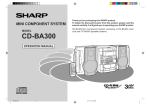
Figure 2-1:
ELISYS QUATTRO - Instrument modules
1
Tray for tip racks and dilution tubes
2
Patient sample and reagent rack unit with bar code scanner
3
Tip eject station, pipettor wash station, pipetting station
4
Test plate compartment, plate transport unit
5
Drawer with wash unit and photometer
6
Position of incubators (below test plates), heated and for room
temperature (dark)
7
Waste bag for tips
8
Guide rail for pipettor (X and Y movement)
9
Pipettor (movement in Z-direction)
ELISYS QUATTRO - User Manual HUMAN
2-1
System Basics
2.2
Top Level Instrument Modules
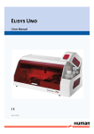
Figure 2-2:
2-2
ELISYS QUATTRO - View on top level
1a
Dilution plates (see chapter 2.2.1 on page 2-3)selftest
1b
Tip racks (see chapter 2.2.1 on page 2-3)
2
Patient sample and reagent unit (see chapter 2.2.2 on page 2-4)
3a
Tip ejection station and waste bag (see chapter 2.2.3 on page 2-4)
3b
Pipettor wash station (see chapter 2.2.3 on page 2-4)
3c
Pipetting station (see chapter 2.2.3 on page 2-4)
4
Test plate compartment with plate transport unit (see chapter 2.2.4 on
page 2-5)
ELISYS QUATTRO - User Manual HUMAN
System Basics
2.2.1
Tray for Tip Racks and Pre-dilution
The tray is accessible via a drawer which is locked automatically as soon as a run
has been started. The tray includes 5 positions for tip racks (300 l or 1100 l tips,
see figure 2-2: position 1b) as well as a position for the dilution rack see figure 2-2: position
1a. 6 additional reagent positions are also available.
Move the tip rack from above straight into the specific position, the groove must fit
into the pin (see figure 2-3: and see chapter 5.1 on page 5-1). The clamp shall fix the tip rack.
Figure 2-3:
Placement of tip racks: A1 is on the top left
ELISYS QUATTRO - User Manual HUMAN
2-3
System Basics
2.2.2
Patient Sample and Reagents Unit with Bar
Code Reader
(See figure 2-2: position 2)
CAUTION: Laser radiation - do not stare into beam!
The bar code scanner is located on the right side at the front of the patient sample
and reagent unit.
The patient sample and reagent unit, accessible via a flap, includes 12 tracks for
sample and reagent racks.
The following racks are supplied:
T:
Sample rack for 20 patient samples (occupies one track).
R:
Reagent rack for 18 bottles for reagents (occupies 1 tracks).
5:
Reagent rack for 5 large bottles for reagents and 8 small
bottles for reagents (occupies 3 tracks).
Each rack includes a contact pin; on racks occupying one track, this pin is located at
the top centre, and on the broader racks at the top right.
The software specifies which track is to be used for the respective rack. This is indicated by a red LED. A reagent rack occupying 3 tracks must be inserted such that
the contact tappet is in contact with the lit up LED.
Each rack has to be inserted up to the limit stop. The respective LED on the rear panel goes off (Loading/Unloading see chapter 5 on page 5-1).
Reloading of patient and reagent racks is possible when the instrument is in the incubation mode.
Keep the flap of this unit closed during a run. It may be opened only for reloading (see chapter 5.2 on page 5-6). Opening the flap while transfer steps are
being performed results in an immediate stop of the pipettor and entry in the
event log.
2.2.3
Tip Ejection Station, Pipettor Wash Station,
Pipetting Station
Tip ejection station and waste bag (see figure 2-2: position 3a)
The opening serves as ejection station for disposable tips. The ejected tip is transported into the waste bag via a slide which is attached to the front side of the instrument. The ejection station is closed by a cover plate which can be pulled off by hand.
With the cover plate removed, the waste bag can be taken out of the holding device
and replaced (Disposal see chapter 5.3 on page 5-7).
Pipettor wash station (see figure 2-2: position 3b)
The pipettor wash station is located next to the tip ejection station.
2-4
ELISYS QUATTRO - User Manual HUMAN
System Basics
Pipetting station (see figure 2-2: position 3c)
The test plates are positioned by the system. Up to 4 plates can be positioned in this
station. A transport unit automatically moves them from the plate compartment to the
correct position where they are processed further (Loading/Unloading see chapter 5 on
page 5-1).
2.2.4
Test Plate Compartment with Bar Code
Scanner
(See see figure 2-2: position 4 or figure 2-5: position 4)
CAUTION: Laser radiation - do not stare into beam!
The bar code scanner is located on the left side at the front of the test plate compartment.
The test plate compartment can be opened only on request by the software. The LED
indicator LD lights up green.
Open the door and place the respective (bar coded) test plate with the holding frame
onto the transport unit so that both pins of the holding frame sit in the openings of the
slide. Position A1 is at the top left (see figure 2-4:). The plate is moved to the pipetting
station following the respective command on the screen.
Figure 2-4:
Inserting a test plate with holding frame
From there the plate is transported - depending on the defined assay - to the various
instrument modules and then back again to the plate loading position (Loading/Unloading see chapter 5 on page 5-1).
2.3
Drawer Instrument Modules
The drawer is automatically locked during a run. The green LED INSTR goes off.
ELISYS QUATTRO - User Manual HUMAN
2-5
System Basics
Figure 2-5:
ELISYS QUATTRO - Bottom drawer pulled out
4
Test plate compartment with plate transport unit (see chapter 2.2.4 on
page 2-5)
5a
Wash buffer container (square) and waste bottles (round) (see
chapter 2.3.1 on page 2-6)
5b
Wash unit for test plates (see chapter 2.3.2 on page 2-6)
6
Incubators (see chapter 2.3.3 on page 2-6)
7
Photometer (see chapter 2.3.4 on page 2-7)
2.3.1
Wash Buffer Container and Waste Bottles
(See figure 2-5: position 5a)
A maximum of 3 bottles (1 x 1 litre, 2 x 2 litres) can be used for various wash buffers;
another position has to be reserved for the cleaning fluid (distilled water) to clean the
washer head.
The connection fitting consists of 4 colour-coded connection pairs: one tubing and
one level sensor each per bottle (Loading see chapter 5.1 on page 5-1).
Two waste bottles are available for the wash unit. One waste bottle contains the liquid
waste which is pumped to the waste container which is positioned below the instrument. The second bottle serves as overflow protection.
2.3.2
Wash Unit for Test Plates with Window
(See figure 2-5: position 5b)
The test plates are moved into the wash unit by the system. The wash process and
the height adjustment of the washer head can be checked via the window.
2.3.3
Incubator Unit
(See figure 2-5: position 6)
2-6
ELISYS QUATTRO - User Manual HUMAN
System Basics
Below the pipetting area for the test plates there are four independent heatable and
shakeable incubator chambers; the test plates are automatically transported into
these incubators and out again according to the assay protocol.
The instrument is equipped with a light-protected storage magazine accommodating
four plates for room temperature incubation. It is located below the incubators in front
of the photometer.
2.3.4
Photometer (Back of Bottom Drawer)
(See figure 2-5: position 7)
The photometer (400 - 700 nm) is installed at the back of the bottom drawer. The
photometer can be equipped with up to 8 filters (end point or kinetic evaluation possible). The photometer is moved out with the bottom drawer.
2.4
Other Instrument Modules
2.4.1
Guide Rail for Pipettor
(See figure 2-1: position 8)
It is used to move the pipettor in the X- and Y-direction.
ELISYS QUATTRO - User Manual HUMAN
2-7
System Basics
2.4.2
Pipettor (Z-Direction)
(See figure 2-1: position 9)
The pipettor includes a complex sensory mechanism. It works with disposable tips.
The pipettor is connected to the system liquid port (See figure 2-6: position 10) via tubing.
A plastic cover with hinged flap protects the visible working area. The
closed position of this flap is monitored by a contact switch. The ELISYS
QUATTRO cannot be operated without this cover or flap, in order to
avoid getting in contact with the working area during a run. If these
safety precautions are not observed strictly, the operator may get hurt
or contract an infection, or the instrument may get damaged.
The system will stop immediately when the instrument cover or the lockable
flap is opened during a run!
2.5
Figure 2-6:
2-8
Connections
ELISYS QUATTRO - Instrument rear panel with connections
ELISYS QUATTRO - User Manual HUMAN
System Basics
10
Tubing connection for system liquid
11
Electrical connection for system liquid level sensor
12
PC port (RS232, 9-pole)
13
Mains fuses, mains switch and mains connection
14
Liquid waste outlet
15
Electrical connection of waste container level sensor
16
Waste from pipettor wash station
17
To protect tubings and cables
18
Ventilation channels
Pass tubings and cables through below the bow.
Don't position the equipment so that it is difficult to operate the disconnecting device!
The ventilation channels must not be blocked. Observe minimum distance of 15 cm!
The level sensors inform you about the status of the respective container (full/
empty). A corresponding message appears on the screen. Before starting a
run, check both containers.
2.6
LED Displays
The LED displays on the instrument front panel (next to the left and right door) have
the following meaning:
Left
ELISYS QUATTRO - User Manual HUMAN
Power
Green, when turned on, otherwise off.
Ready
Green, when ready for a run, otherwise
off (e.g. in case of Error or during initialisation)
Error
Yellow, when instrument error has
occurred, otherwise off.
2-9
System Basics
Drawer
Green, when left drawer has been cleared
for loading and unloading of pre-dilution
plates and tips, otherwise off.
Load
Green, when plate compartment can be
opened, otherwise off.
Instrument
Green, when instrument drawer (bottom
drawer, see figure 2-1: position 5 can be
opened.
Right
2-10
ELISYS QUATTRO - User Manual HUMAN
System Basics
2.7
Principles of Methods
2.7.1
Absorbance Photometry
The measurement principle of absorbance photometry plays the most important role
in clinical chemistry. With this method the intensity of a monochromatic light beam of
a suitable wavelength is compared before and after passing through a sample. The
degree of attenuation of intensity of the light beam provides a measure for the concentration of the substance under investigation. The photometer consists of a polychromatic or monochromatic light source. In the case of the ELISYS QUATTRO, this
is a halogen lamp which emits a spectrum. The desired wavelength is filtered out using a wavelength selector (i. e. a filter). The light with this wavelength passes through
the sample with the substance to be measured in an optically clear solution. A part
of the light is absorbed in the sample. The intensity of the light coming out of the sample is measured with a measuring cell (detector). The light striking the detector is
converted into an electrical signal and stored as the measurement signal.
2.7.2
Bichromatic Measurement
In the case of the bichromatic measurement principle measurements are performed
at two wavelength, the measuring and the reference wavelength. The measuring
wavelength is close to the absorbance maximum of the chromogen. The absorbance
is mainly dependent on the amount of chromogenic substance in the sample. The
reference wavelength lies outside the absorbance range of the chromogen and indicates the blank value of the sample. The absorbance value of the reference wavelength is subtracted from the absorbance value of the measuring wavelength. In this
manner external influences such as scratches on the microtiter plate, dust, turbidity
of the solution, and the drift of the electronic measuring instrument can be compensated.
ELISYS QUATTRO - User Manual HUMAN
2-11
System Basics
2-12
ELISYS QUATTRO - User Manual HUMAN
Software Structure and Operation
3
Software Structure and Operation
3.1
Basic Information about Operation
ELISYS QUATTRO
The user program Phoenix is a PC program running under Microsoft Windows 95 as
well as Windows 2000. The usual Windows conventions apply. Deviations from
these conventions are described where appropriate.
Explorer Tree
Some windows show an explorer tree on the left-hand side and the selected item on
the right-hand side. Clicking on the plus sign of a folder on the explorer tree opens
the respective options, clicking on the minus sign closes the respective folder. Clicking on an item shows the respective page of the corresponding file.
This presentation is used for the windows:
•
Assay Protocol
To define assay process steps (pipetting, washing, incubating, measurement,
etc.).
•
Panel Definition / Set-up Panel
To combine assays and samples on test plates to create a worklist for routine.
•
Worklist
To check the conditions for a certain worklist.
ELISYS QUATTRO User Manual HUMAN
3-1
Software Structure and Operation
3.2
Menu Guidance
3.2.1
General Menu Guidance
Menu
Item
File
New
Creates a new file, e. g. a worklist or an assay.
The N e w dialogue box opens and the following file types can be selected: Assay, Worklist, Spectral Response, Patient Results
Report, QA Analysis Report, Job List.
New | W orklist
Creates a new worklist.
Open
Opens an existing file, e. g. an assay protocol
or a report file (file types see F i l e | N e w ).
Close
Closes the displayed file.
Save
Saves the active file (e. g. worklist, report).
Save As
Saves active file (e. g. worklist, report) under a
new name.
Print...
Prints the active document.
Print Preview
Shows the active document as print preview.
Print Setup...
Defines the printer and printing options.
Recent Prot oc ols
>
Shows the last opened and already saved
assay protocol files for selection.
Recent Results >
Shows the last opened and already saved
result files for selection.
Recent Worklists
>
Shows the last opened and already saved
worklist window for selection.
Exit
Terminates the program.
Toolbar
Shows/hides toolbar.
Status Bar
Shows/hides status bar at the bottom of the
screen.
System Setup...
Definition of instrument parameters.
Selftest
Performance of a selftest (initialisation).
Verify
Checks the photometer
View
Utilities
3-2
Icon
Function
ELISYS QUATTRO User Manual HUMAN
Software Structure and Operation
Menu
Window
Help
Item
Icon
Function
Patient Details...
Definition of detailed patient data.
Options...
Definition of software parameters.
New Window
Opens a new window.
Cascade
Cascades the active windows.
Tile
Tiles the active windows.
Arrange Icons
The icons can be re-arranged.
*.*
Shows the names of all currently active windows.
Help Topics
Calls on-line help.
A b o u t Ph o e n i x . . .
Shows the version number of the Phoenix software.
Table 3-1:
General menu guidance
ELISYS QUATTRO User Manual HUMAN
3-3
Software Structure and Operation
3.2.2
Worklist Menu Guidance
Menu
Item
Edit
Panel Definition...
Opens the Set-up Panel dialogue box (only
possible with open worklist) with editing options
of the current worklist.
Panel Options...
Settings for processing the worklist.
Optimise
Optimises processing of the defined run.
L o t s p e c i f i c v a lu e s
Display and input of the lot specific information
and the required reagents for the displayed
worklist.
Start
Starts the loading dialogue; once the loading
dialogue has been completed, a run using the
current worklist can be started.
Stop
Stops the current run. The run can be continued again and one or several plates can be
removed from processing. Or the entire run can
be aborted completely.
Load additional
tips
Allows the reloading of pipette tips.
Module Schedule
Graphical display of the processing of a worklist (module-specific).
P l a t e Sc h e d u l e
Graphical display of the processing of a worklist (plate-specific)
System Utilities
Manual plate control.
View
Utilities
Icon
Table 3-2:
3-4
Function
Worklist menu guidance
ELISYS QUATTRO User Manual HUMAN
Software Structure and Operation
3.2.3
Result Menu Guidance
Menu
Item
Icon
Edit
Outliers...
Shows the O u t l i e r s dialogue. This dialogue
shows all result values. Changes of these values are marked in the result report.
Parameters...
Shows the L o t S p e c i f i c V a l u e s dialogue. This dialogue shows all data of the reagents. Changes of these datas are marked in
the result report.
Assays...
Shows the C h a n g e A s s a y P r o t o c o l
dialogue. This dialogue shows the used assay.
Change of these assays are marked in the
result report.
Retest...
Shows the R e t e s t dialogue. This dialogue
shows all tested patients. Select one or more
patients you want to test it with these assays
again.
Copy to clipboard
Copy selected Q u a n t i t a t i v e R e s u l t s to
the windows clipboard.
Vi e w
Recalculate
After having changed the parameters for the
assay this function starts the recalculation. The
data reduction of the raw data will be done
using the new parameters.
Utilities
Export Results
Shows a dialogue to start the export of the
results to a file and/or to LIMS.
Table 3-3:
Function
Result menu guidance
ELISYS QUATTRO User Manual HUMAN
3-5
Software Structure and Operation
3.3
File Types
File
Extension Path
File polling format setting of the import file for host systems. For detailed information see ELISYS QUATTRO
’Connectivity Manual’ Cat.No.: 16300/4, available on
request.
*.apm
C:\Phoenix
Assay protocol files
*.asy
C:\Phoenix\Assays
Files documenting daily data communication between PC
and ELISYS QUATTRO instrument as well as error messages.
*.log
C:\Phoenix\Eventlogs
Coordinate files for e.g. pre-dilution plates
*.mpc
C:\Phoenix
Coordinate files for the racks
*.rac
C:\Phoenix
Result files
*.res
C:\Phoenix\Results
Spectrum files (contain data of a spectrum acquisition)
*.spe
C:\Phoenix
selftest files with information about the selftests that were
performed.
*.tst
C:\Phoenix
Export files in ASCII format
*.txt
C:\Phoenix\Export
ASCII patient data import files can be downloaded from a
host computer to the Phoenix software (patient with
associated assays).
*.txt
For host connection
Verification report files
*.ver
C:\Phoenix
Worklist files
*.wor
C:\Phoenix
Table 3-4:
3-6
File types
ELISYS QUATTRO User Manual HUMAN
Performing a Test Run
4
Performing a Test Run
4.1
System Start
1. Start the ELISYS QUATTRO instrument.
2. Start the computer.
3. Start the Phoenix software by clicking on the
respective icon on the desktop or choosing
Start | Phoenix.
4. Click on the O K button.
You don’t need a U s e r N a m e or P a s s word
To run the Phoenix software in demo mode tick the D e m o m o d e check box.
The Phoenix software can be run without the ELISYS QUATTRO instrument.
5. After that a system selftest is performed and
checks all instrument functions. The result of this
instrument check is then displayed on the screen.
ELISYS QUATTRO User Manual HUMAN
4-1
Performing a Test Run
4.2
Input of Patient Data
4.2.1
Manual Input of Patient Data
1. Select U t i l i t i e s | P a t i e n t D e t a i l s or click
on the icon on the tool bar and define the patients
and the associated tests in the P a t i e n t E d i tor .
2. Click on the A d d P a t i e n t ( s ) button to open
the A d d P a t i e n t ( s ) dialogue box.
3. Enter the first sample name in the F i r s t
p a t i e n t I D.
4. Optionally, consecutive sample numbering may
be entered blockwise. To do this, the number of
the following samples has to be entered in the
Nu m b e r o f p a t i e n t s text box. The software
numbers the following samples con-secutively.
5. Click on the O K button.
The patient editor only accepts letters and numbers as patient ID. The use of
any spe-cial characters such as "%", "-", "$", "€","'", "|", "/", "\", ";", "," or "."
when creating a patient ID or receiving from the host computer is forbidden.
4-2
ELISYS QUATTRO User Manual HUMAN
Performing a Test Run
The software returns to the P a t i e n t E d i t o r and
shows the patients that were entered new.
Repeat this step, if necessary, for further patient IDs.
6. Click on the A d d T e s t ( s ) button in the
Patient Editor.
7. In the following A d d T e s t s dialogue assign
the patients to the assays.
To do this, select the patients and then the
assay(s).
8. Click on the O K button.
You will find further information to the tests in the manual of the respective
test.
ELISYS QUATTRO User Manual HUMAN
4-3
Performing a Test Run
4.2.2
Input of Bar Coded Patient Samples
1. Insert samples into the ELISYS QUATTRO with
the worklist closed.
The patient bar codes are read.
The dialogue box depicted to the right appears on
the screen, showing the identified bar codes.
2. From the respective list box (with all available
assays), select the respective assay by clicking
on the column header.
3. Then assign the samples by clicking on the field
in the respective assay column.
4. Click on the C l o s e to accept the selection.
5. Proceed accordingly for each further sample
rack.
The patient editor only accepts letters and numbers as patient ID. The use of
any spe-cial characters such as "%", "-", "$", "€","'", "|", "/", "\", ";", "," or "."
when creating a patient ID or receiving from the host computer is forbidden.
As an alternative, patients may be entered via host. In this case you may start
directly with creating a worklist (see chapter 4.3.1 on page 4-5).
You will find further information to the tests in the manual of the respective
test.
4-4
ELISYS QUATTRO User Manual HUMAN
Performing a Test Run
4.3
Worklist Definition
4.3.1
Create New Worklist
1. Click the N e w | W o r k l i s t button (or select
F i l e | N e w and then select W o r k l i s t in the
dialogue box).
2. The S e t - u p P a n e l dialogue box is displayed.
• In case of non-bar coded samples this dialogue
box is empty, as shown in the figure to the right.
• With bar coded samples a worklist with plates,
assays and patients is suggested in accordance
with the assignment of the assays to the samples
and displayed in the Explorer tree, using one
assay per plate.
Click on the O K button to accept this proposal
and proceed with defining several plates (see
chapter 4.3.3 on page 4-8) or with input of reagent
data (see chapter 4.3.4 on page 4-8).
If the proposal is modified, the plate panel has to
be deleted with De le te and a new plate panel
has to be defined.
In the Se t - u p P a n e l dialogue box the plate(s)
and the plate layout are defined for the selected
worklist via the top 3 buttons. Click on the U n d o
button to undo the last step. Click on the O p e n
Pa n e l button to open a stored plate panel. Click on
the S a v e P a n e l button to save the defined plate
panel. The assigned patients are not stored.
3. Click on the A d d Pl a t e . . . button.
Plate 1 is entered in the Explorer tree.
ELISYS QUATTRO User Manual HUMAN
4-5
Performing a Test Run
4. Click on the A d d A s s a y . . . button.
The Open dialogue box shows all available
assay files (*.asy) in the selected subdirectory.
5. Select the desired assay file.
6. Click on the Open button.
The plate panel pre-defined in the selected assay
protocol is entered into the plate depicted in the
S e t - u p P a n e l dialogue box (except tests). In the
Explorer tree the assay protocol is displayed as a
folder.
7. Click on the A d d P a t i e n t . . . button to assign
the patients to the selected assay.
The S e l e c t P a t i e n t ( s ) dialogue box
appears. It contains only the patient IDs for which
the respective assay has been selected in the
Pa t i e n t E d i t o r .
The dialogue indicates all patients with a ’* ’,
which are already loaded on the instrument.
8. Select patients with the mouse or press on the
Se le ct All button to select all of the loaded
samples to the worklist.
9. Click on the O k button.
If you did not enter any patient codes before creating the worklist this window
does not contain any patients. In this case you can assign assay/patients via
the P a t i e n t D e t a i l s . . . button in the S e t - u p P a n e l dialogue box.
If a sample is already assigned to the worklist it disappears from the S e l e c t
P a t i e n t ( s ) dialogue.
To run the same patient with the same assay on more then one plate the option A l l o w m u l t i p l e d e t e r m i n a t i o n s must be selected.
4-6
ELISYS QUATTRO User Manual HUMAN
Performing a Test Run
The selected patients are listed in the S e t - U p
Pa n e l dialogue box as contents of the assay
folder.
4.3.2
Defining Several Assays per Plate
1. The respective plate must be active.
If not: click on the plate name in the Explorer tree.
2. Click on the A d d A s s a y . . . again to place a
second assay on the same plate.
The panel of the first assay is hidden.
3. Select assay and patients as described in the
steps before (see chapter 4.3.1 on page 4-5).
Only possible with identical incubation parameters!
The item S t a r t a s s a y w i t h a n e w s t r i p must always be enabled!
ELISYS QUATTRO User Manual HUMAN
4-7
Performing a Test Run
4.3.3
Defining Several Plates
1. Click on the A d d P l a t e . . . button.
2. Click on the A d d A s s a y . . . button and select
an assay protocol (see chapter 4.3.1 on page 4-5).
3. Click on the A d d P a t i e n t . . . button and select
patients.
The expanded Explorer tree is displayed along
with plate 2 showing the panel of the active
assay.
4. Repeat this steps for further plates.
Further possibilities:
•
•
•
Click on the plus sign of an plate folder to view
the respective assays in the Explorer tree.
Click on the plus sign of an assay folder to view
the respective patient IDs in the Explorer tree.
Change the order of plates via the M o v e U p
and M o v e D o w n buttons.
4.3.4
Input of Reagent Data
1. After all required plates have been defined in the
Se t - u p P a n e l dialogue box, click O K to
close the dialogue box.
The L o t S p e c i f i c V a l u e s F o r : Pl a t e 1
dialogue box for of the active worklist is displayed. It includes a tab for each assigned assay,
listing the required reagents for the respective
assay
2. For this assay and - if available - for the other
assays on this plate, that are located on further
tabs, you have to enter the lot-specific data.
The different assay tabs must be selected by hand!
3. Click on the OK button.
The first assay of the next plate is displayed. This
and possibly following assays and plates have to
be treated as described above.
After the last plate the W o r k l i s t window is displayed (see next chapter).
4-8
ELISYS QUATTRO User Manual HUMAN
Performing a Test Run
4.4
Start a Worklist
4.4.1
The Worklist Window
When all dialogues have been processed as
described above, the W o r k l i s t window with the
Worklist parameters and the Explorer tree appear.
The start time and end of the run as well as the plate
status (loaded/not loaded/error), the selected assays
and the number of patients are displayed.
In the Explorer tree click the p l u s sign of the worklist folder and then the respective item.
•
Click on the S t a r t button to start the worklist
and open the L o a d dialogue (see chapter 4.4.2 on
page 4-12).
4.4.1.1
Schedule
The S c h e d u l e shows the process diagram for the
worklist. It can be presented as M o d u l e S c h e d ule (see figure) or as Pl a t e S c h e d u l e . The
selection is made via the View menu.
The individual plates and process steps are displayed in different colors.
ELISYS QUATTRO User Manual HUMAN
4-9
Performing a Test Run
4.4.1.2
Plate Layout
The Pl a t e l a y o u t shows the exact plate layout.
All plate layouts defined in the current worklist are
displayed one below the other.
The view can be switched between L a y o u t
L a b e l (e. g. T1, T2 ...) and P a t i e n t I D s (e. g.
318261, 513255 ...)
4.4.1.3
Reagent Requirements
The Re a g e n t r e q u i r e m e n t s shows the
required reagents (Example).
Make sure the required reagents are available and
there is sufficient space in the liquid waste container.
4-10
ELISYS QUATTRO User Manual HUMAN
Performing a Test Run
4.4.1.4
System Status
The S y s t e m s t a t u s shows the working area
including status messages. Depending on the type of
loading (bar coded, non-bar coded samples or host
connection), this presentation differs:
•
•
Bar coded samples:
Sample and reagent racks are depicted.
Non-bar coded samples and host connection:
No racks are depicted yet.
4.4.1.5
Active Event Log
The A c t i v e e v e n t l o g shows the communication protocol, listing all steps of the ELISYS QUATTRO (Example).
•
•
•
Important actions in this context are warning and
error messages; they are displayed in red.
Reactions by the user on these actions are displayed in green.
User actions such as manual definition of reagents are also displayed in red.
ELISYS QUATTRO User Manual HUMAN
4-11
Performing a Test Run
4.4.1.6
Job List
The Job list shows the allocation of patient IDs
and tests to be performed in a list.
4.4.2
Loading Samples and Reagents
CAUTION: Laser radiation - do not stare into beam!
Allocate the vials only into suitable locations. An incorrect allocation may
cause errors in dispensing.
Samples having particulate matter, turbity, lipaemia, foam, or erythrocyte debris may require clarification by filtration or centrifugation before testing.
The use of primary tubes with gel separator requires a careful check of the
sample volume above the gel to avoid any possible errors in dispensing.
When refilling a reagent bottle never exceed the bottle shoulder. An over-filling may lead to an incorrect dispensing.
4-12
ELISYS QUATTRO User Manual HUMAN
Performing a Test Run
4.4.2.1
Loading Bar Coded Patient Samples and Reagents
The sample and reagent area on the screen are
empty.
The required resources are displayed as circles in
different colours in the top right corner of the screen.
You can view the respective name by moving the
cursor over these circles. An inserted rack is
depicted graphically and the loaded resources are
automatically allocated.
1. Right LED lights up red.
2. Insert first rack into the right track.
3. The bar codes are read and the rack and the
available reagents are identified.
4. If the rack has been inserted properly up to the
limit stop the LED goes off. On the screen, the
loaded resources from the pool of unallocated
resources are allocated to the inserted rack
(marked with a cross in the rack position), since
they are bar coded and are therefore identified.
5. The next empty track is marked by a red LED.
Proceed as described in the preceding step (see
chapter 5 on page 5-1).
Always load racks from right to left.
4.4.2.2
Allocation of Non-bar Coded Reagents and Samples
The sample and reagent area on the screen is
empty.
After insertion of the racks only the rack types with
empty positions are depicted. Unallocated but
required resources are displayed as circles in different colours in the top right corner of the screen. You
can view the respective name by moving the cursor
over these circles.
ELISYS QUATTRO User Manual HUMAN
4-13
Performing a Test Run
1. Right LED lights up red.
2. Insert first rack into the right track.
3. Allocate the non-bar coded reagents on the
screen by dragging the mouse - corresponding to
the actual loading - to the reagent rack.
Each dot clearly corresponds to one reagent.
4. Insert the required racks one by one into the
tracks marked by the red LED and allocate the
resources as described above (from right to left).
5. On the screen, allocate the samples by dragging
the mouse - corresponding to the actual loading to the sample racks. Each dot clearly corresponds to one patient tube or one reagent.
"Dragging" means clicking with the mouse on a resource, keeping the mouse
button pressed down, moving it to the desired location, and releasing the
mouse button again.
Auto Arrange Samples:
•
•
Load procedure 1:
Load all sample racks and press on the A u t o
Ar r a n g e button. The fill direction of the samples starts at position one of the rack placed in
the far left side.
Load procedure 2:
Load the first sample rack and press on the
Au to Ar ran g e button. The fill direction of the
samples starts at position one of the sample rack
just inserted.
Proceed this sequence with the remaining racks.
The A u t o A r r a n g e function always arranges the samples by using the
N o n e sort order as selected in the P a t i e n t E d i t o r . After its use, it is recommended to perform a random manual verification of the sample IDs in the
rack. This type of verification is also recommended when working with a job
list manually created for sample tubes without barcodes.
4-14
ELISYS QUATTRO User Manual HUMAN
Performing a Test Run
4.4.3
Loading other Required Resources
Load disposable tips and dilution plates as well as
wash buffer and distilled water as shown on the
screen. The number and size of the required tips is
displayed.
Observe defaulted positioning!
Tip racks depicted in dark grey and light grey must
be loaded in addition.
• 300 l tips are depicted in dark grey.
• 1100 l tips are depicted in light grey.
Only complete tip racks should be loaded.
Tip racks depicted in red are already available on the
instrument, tips may have been removed already.
The number of tips that are still available is taken into
account by the software.
You can view the respective name of the dilution
plate by moving the cursor over this plate.
Check if sufficient tips are available and if the tip size displayed agrees with
the position on the instrument!
Please carefully check the tip racks allocation, following the specific
color code and type in the software. A tip misplaced can not be recognized by the instrument and may cause mechanical damage!
ELISYS QUATTRO User Manual HUMAN
4-15
Performing a Test Run
4.4.4
Reagent Volume Check
After loading and allocation of all required resources,
press on the O K button. A volume check of all reagents is carried out automatically.
If the reagent check shows that the volume of one
reagent is low, a S y s t e m E r r o r dialogue box
appears alerting you about any insufficient volume.
To refill the respective reagent or to replace it by a
new bottle, the respective reagent rack has to be
moved out, reagent has to be refilled or the bottle
replaced, respectively and the rack has to be
inserted again.
•
•
•
If you press on the R e f i l l B o t t l e . . . button,
the volume is checked once more.
If the reagent was identified manually, the position in the rack has to be allocated once more
(see above).
If the reagent cannot be supplied, press on the
A b o r t W o r k l i s t button.
This will abort any further volume check.
The I g n o r e button skips the reagent check for
this specific reagent (the insufficient volumne is
logged) and continues with the reagent check for
the next one.
Do not change any reagent positions!
4-16
ELISYS QUATTRO User Manual HUMAN
Performing a Test Run
4.4.5
Plate Loading
Plate loading may be started as soon as all reagents
are available in sufficient quantity.
4.4.5.1
Plate Loading
The plate compartment LED lights up green, the dialogue box depicted to the right appears on the monitor. Open door and place test plate (position A1 on
the rear left) with the holding frame correctly on the
plate transport unit (see chapter 5.1 on page 5-1).
1. Enter the plate name in the field P l a t e I D .
2. Click on the O K button.
The test plate is first moved into the photometer to
check for an adequate strip filling for the performance of this assay. Then the plate is placed on the
pipettor station. The plate transport unit moves back
to the home position and the L o a d P l a t e dialogue box requests the 2nd plate.
3. Repeat procedure until all plates of the worklist
have been inserted.
At this point the system does only recognise if a holding frame has been loaded!
ELISYS QUATTRO User Manual HUMAN
4-17
Performing a Test Run
4.4.6
Starting and Processing a Run
As soon as all plates have been loaded, the system
starts the run. All loading doors must be closed so
that the run can be started!
The plates are processed in accordance with the
defined process steps of the selected assays.
During the run all worklist options (see chapter 4.4.1 on
page 4-9) can be viewed. In the S c h e d u l e mode
the current time and thus the current operation is
marked by a vertical indicator.
At the end of the entire run the system prompts you
to unload plates. Unload plates one by one. Results
can be viewed as soon as all plates have been
unloaded.
4.4.6.1
Clot Detection Error Handling
Dependent on the attitude in the test definition
("Raise alarm and stop", "Log and continue" or "Manual pipette at end of step") the error handling is different at a clot detection.
Action on error "Raise alarm and stop"
If a clot is detected, the system stops and shows a
message with the following buttons:
Skip Sample:
•
•
•
•
The pipettor moves to the eject position to
remove the tip.
Entry in the Eventlog.
The next sample will be pipetted.
The result file flags all samples with “Clot
detected” where a clot was detected.
A b o r t P l a t e:
•
•
•
An additional message comes up to confirm the
plate abort process.
The pipettor moves to the Eject position to
remove the tip.
If available, the next sample of the next plate will
be pipetted.
C o n t i n u e:
•
•
The sample is pipetted into the appropriate well of
the micro plate.
The result file flags all samples with “Clot
detected” where a clot was detected.
4-18
ELISYS QUATTRO User Manual HUMAN
Performing a Test Run
Action on error “Log and continue”
If a clot is detected, the system does not show a
message and continues with:
•
•
•
•
The pipettor moves to the eject position to
remove the tip.
Entry in the Eventlog.
The next sample will be pipetted.
The result file flags all samples with “Clot
detected” where a clot was detected.
Action on error “Manual pipette at end of step”:
If a clot is detected, the system does not show a
message and continues with:
•
•
•
•
•
The pipettor moves to the eject position to
remove the tip.
Entry in the Event log.
The next sample will be pipetted.
At the end of the pipetting step, a message
comes up and shows you all samples which were
not pipetted or were a clot was detected.
The result file flags all samples with “MP” where a
clot was detected.
ELISYS QUATTRO User Manual HUMAN
4-19
Performing a Test Run
4.4.7
Pausing or Cancelling a Run
Click the S t o p button to stop the current run.
The ELISYS QUATTRO system stops and shows
the S y s t e m P a u s e d dialogue box.
•
•
Click R e s u m e to continue the run.
Select a plate and click Ab o r t P l a t e ( s ) to
remove the plate.
• Click A b o r t A l l P l a t e s to remove all plates.
Any interruption of a run is documented with the time
of its occurrence.
If an error occurs, a run is automatically stopped. A
dialogue box with a message describing the error is
displayed. Error messages have to be confirmed
accordingly and you may then continue or abort the
run.
The ELISYS QUATTRO unloads an aborted plate at the next appropriate moment. You must unload this plate, otherwise the worklist will be paused! An
already started process step with another plate will be finished first.
4.5
Results of a Run
Upon complete processing of a plate, the results are
saved to a result file and displayed on the screen,
which can be printed in individual parts or as a
whole.
•
•
Click on the plus sign in front of file name to open
the folder tree of the result file.
Click on the individual symbol of the folder to display its contents in the right window.
Don’t approve results without reviewing the original results printout
and the events of the run!
4-20
ELISYS QUATTRO User Manual HUMAN
Performing a Test Run
4.5.1
Results Report
4.5.1.1
Laboratory Details
Select the item L a b o r a t o r y D e t a i l s to open
the window depicted to the right, showing information about the laboratory (e.g. name, address, etc.)
This information can be entered and edited via the
menu items U t i l i t i e s | O p t i o n s | L a b o r a t o r y.
4.5.1.2
Title Block
The T i t l e Bl o c k identifies the assay respective
assay definition file the results have been generated
with. It provides information on the plate ID and the
person responsible for running the test, specifies the
assay used, saves date and time the test has been
finished and shows certain default settings of the
photometric measurement such as the overflow limit
and the wavelength as well as the reference wavelength. Furthermore, important error messages that
came up in the course of processing the assay
respective the worklist are already displayed at this
point.
4.5.1.3
Reader
The blank value is displayed in the R e a d e r result
section. This section can also be used to show the
raw data.
4.5.1.4
Quantitative Results
The window Q u a n t i t a t i v e R e s u l t s shows the
graph which is created with the standards defined in
the assay.
ELISYS QUATTRO User Manual HUMAN
4-21
Performing a Test Run
4.5.1.5
Combined Report
The Co m b i n e d R e p o r t shows all patient IDs,
results, flags etc. in one table. It gives a short overview about all relevant data.
The samples are identified by the patient ID. The
individual wells are identified (alphanumerically),
evaluated, calculated and, if necessary, flagged.
4.5.1.6
Validation Criteria
The window V a l i d a t i o n C r i t e r i a indicates if
the control values of the test meet the defaulted criteria.
If the values of the control well are within the limits
specified by the formula in this field, the test is considered valid and can therefore be evaluated.
If one of the criterias is failed, the test will not be
evaluated.
4.5.1.7
Qualitative Results
The window Q u a l i t a t i v e R e s u l t s provides
information regarding the cut-off value of the test.
Three options are available:
•
•
•
Pos: positive result
Neg: negative result
Eqv: result in the greygreygrey range.
4.5.1.8
Events
The Ev e nts window shows information on important actions performed by the analyzer and subsequent reactions by the user.
•
•
•
Important actions in this context are warning and
error messages; they are displayed in red.
Reactions by the user on these actions are displayed in green.
User actions such as manual definition of reagents are also displayed in red.
4-22
ELISYS QUATTRO User Manual HUMAN
Performing a Test Run
4.5.1.9
Lot Specific Values
The window L o t S p e c i f i c V a l u e s, if selected
in the assay-protocol, includes the lot data entered
before the start of the worklist, the reagents used
and the test kits.
4.6
Re-Loading
To insert a new plate during a running worklist, this
can be done by re-loading.
1. Input of additional patient (bar coded or nonbar coded):
Bar coded patients:
First, insert the bar coded patient samples and
then assign the assays in the Pa t i e n t E d i t o r
(see chapter 4.2.2 on page 4-4). Processed sample
racks (red flashing LED) may be removed.
Non-bar codedNon-bar coded patients:
First, enter the additional patients in the
P a t i e n t E d i t o r (see chapter 4.2.1 on page 4-2).
2. Select the item E d i t | P a n e l D e f i n i t i o n .
The S e t - u p P a n e l dialog box appears showing the current plate panel.
3. Define additional plate panel via the A d d
P l a t e , Ad d A s s a y and A d d P a t i e n t buttons (see chapter 4.3.3 on page 4-8).
4. After definition of the additional plate panel, click
on the O K button.
5. Enter all L o t S p e c i f i c V a l u e s (see
chapter 4.3.4 on page 4-8).
After confirmation of the lot-specific data, the L o a d
dialogue box appears (possible during incubation
phases) or the system specifies that the system is
currently busy. The times for loading resources and
plates are depicted in the worklist schedule.
When the specified time is over, select the item
E d i t | P a n e l D e f i n i t i o n once more. The
L o a d dialogue box appears.
ELISYS QUATTRO User Manual HUMAN
4-23
Performing a Test Run
6. Patient samples:
Insert sample racks and allocate sample symbols
with the mouse to the new sample rack (see
chapter 4.4.2 on page 4-12).
Processed sample racks (flashing red LED) can
be removed.
7. Reagents:
Refill or add additionally required reagents as
shown on the screen (see chapter 4.4.2 on page 4-12).
The reagent symbols are automatically allocated
to the respective positions.
8. Disposable tips and dilution plates:
Refill disposable tips, dilution plates, wash buffer
and distilled water as shown on the screen (see
chapter 4.4.3 on page 4-15).
Allocate the vials only into suitable locations. An incorrect allocation may
cause errors in dispensing!
When refilling a reagent bottle never exceed the bottle shoulder. An over-filling may lead to an incorrect dispensing!
Never remove a rack while still in use. Remove it only when the related LED
is flashing. If a sample rack is removed which is still in use, all samples not
already pipetted out of this rack will be flagged with R e m o v e d and not calculated.
Make sure that the flap of the reagent unit is closed after re-loading.
9. After loading and allocation of all required
resources confirm the dialogue with O K . A volume check of all reagents is carried out automatically (see chapter 4.4.4 on page 4-16).
After the volume check the worklist is calculated new
(interlacing or adding new plates/assays to be processed). Further processing is then carried out in
accordance with the new worklist.
4-24
ELISYS QUATTRO User Manual HUMAN
Performing a Test Run
4.7
Quality Control Analysis Report (Levey
Jennings Plot)
The quality control analysis report (Levey Jennings plot) shows the results of a selected reagent
over a period of time.
To generate a Q A An a l y s i s R e p o r t you have
to activate the QA-analysis by defining Q A L a b e l s in the L o t S p e c i f i c V a l u e s while
preparing a worklist (see chapter 4.3.4 on page 4-8).
A QA-Label is the label which is used in the assay
layout definition (e. g. NC, NC1, PC2 etc.).
1. Select F i l e | N e w .
2. In the N e w dialogue box select the file type Q A
A n a l y s i s Re p o r t.
3. In the Q . A . A n a l y s i s dialogue box select in
the box C o n t r o l s the respective reagent.
4. Select in the box Ba tc h Nu mb er s the
respective bach number.
5. Select the period of time in the boxes D a t e
f r o m and t o.
6. Click O K to confirm the entries.
The system shows you the quality control analysis report (Levey Jennings plot).
4.8
Patient Result Report
The patient result report shows a compact summary
of the patient results of all selected assays.
1. Select F i l e | N e w .
2. In the New dialogue box, select the file type
Patient Result Report.
3. In the P a t i e n t R e s u l t dialogue box, select
A l l P a t i e n t s or I D s b e t w e e n.
If you selected I D s b e t w e e n than enter the
first ID and the last ID in the two boxes.
4. Select up to five assays.
5. Select the period of time in the boxes D a t e
f r o m and D a t e t o .
ELISYS QUATTRO User Manual HUMAN
4-25
Performing a Test Run
6. Select the S o r t O r d e r .
7. Click O K to confirm the entries.
The system shows you the patient result report.
8. Select V i e w | D e t a i l to show a detailed list,
including the B a t c h N u m b e r of the Kit (if
entered, see chapter 4.3.4 on page 4-8).
4-26
ELISYS QUATTRO User Manual HUMAN
Loading - Unloading - Disposal
5
Loading - Unloading - Disposal
5.1
Loading (Instrument at Hold)
5.1.1
Refill System Liquid
1.
2.
Open screw cap of system liquid container and refill system liquid or replace
container.
Close screw cap again and watch for correct seat of level sensor and connections.
5.1.2
1.
2.
3.
4.
Hold bottom drawer with both hands at the bottom edge and pull it out. The
LED INSTR must light up green.
Open cap of wash container and refill the respective liquid or replace bottle.
Close cap again and watch for correct seat of level sensor and connections.
Close bottom drawer again, so it clicks into place (audible click).
5.1.3
1.
2.
3.
3.
Position Dilution Plates
Pull very left drawer out. The LED DWR must light up green.
Place dilution plate(s) in the respective positions as shown in the L o a d dialogue box. The position 1 is on the rear.
Push in drawer again up to the limit stop (audible click), overcoming a slight
resistance.
5.1.4
1.
2.
Refill Wash Liquid
Load Tip Racks
Pull very left drawer out. The LED DWR must light up green.
Place tip rack - as illustrated in the drawing below - into the holding device of
the instrument, so that the pin sits in the groove of the tip rack.
Push in drawer up to the limit stop (audible click), overcoming a slight resistance.
Please carefully check the tip racks allocation following the specific colour
code and type in the software. A tip misplaced can not be recognized by the
instrument and may cause mechanical damage!
ELISYS QUATTRO User Manual HUMAN
5-1
Loading - Unloading - Disposal
Figure 5-1:
5.1.5
Inserting a tip rack
Load Sample and Reagent Racks
CAUTION: Laser radiation - do not stare into beam!
The red LED indicates the track where the rack is to be inserted. When loading reagent racks that occupy three tracks it must be ensured that the rack with its right track
(= position of contact tappet) is placed on the tracks with the red LED. The bar code
labels must face right the bar code reader.
Samples having particulate matter, turbity, lipaemia, foam, or erythrocyte debris may require clarification by filtration or centrifugation before testing.
The use of primary tubes with gel separator requires a careful check of the
sample volume above the gel to avoid any possible errors in dispensing.
Never remove a rack while still in use. Remove it only when the related LED
is flashing. If a sample rack is removed which is still in use, all samples not
already pipetted out of this rack will be flagged with R e m o v e d and not calculated.
5-2
ELISYS QUATTRO User Manual HUMAN
Loading - Unloading - Disposal
If reagents were not identified or placed without barcode, the user has to
make sure that the manually allocated positions correspond to the actual
placement on the reagent rack. Manually allocated reagents are identified in
the result printout and in the log file.
5.1.5.1
1.
2.
3.
Loading Reagent Racks
Insert rack on that track that is marked by the red LED on the rear panel.
Place rack in front of the track and then push evenly up to the limit stop (with
the pin in the contact pin hole on the rear panel). The bar code labels must
face right towards the bar code scanner.
The LED goes off and jumps to the next position that can be loaded. (A red
flashing LED indicates that the rack wasn’t identified correctly. Pull out the
rack and insert it once more.) A graphical representation of the correctly
inserted rack appears on the screen. From the pool of unallocated resources
in the right-hand side of the screen, the loaded reagents are allocated to the
rack in accordance with the identified loading. Place the mouse pointer on the
reagent to check the ID.
Insert the next racks as described.
The software shows all resources prior to allocation in the area U n a l l o c a t e d r e s o u r c e s in their respective colour (as defined in the reagent database).
All automatically allocated samples and reagents are c r os s e d, all manually allocated samples and reagents are no t c r o s s ed .
Loaded reagents which are identified by a bar code and which are not needed for the
current worklist are presented in black.
Reagents that have not been identified are not displayed in the reagent area, the position remains white. The symbols of these reagents can be allocated from the area
Un a l l o c a t e d r e s o u r c e s to the respective positions with the mouse.
See notes on page 5-2
ELISYS QUATTRO User Manual HUMAN
5-3
Loading - Unloading - Disposal
5.1.5.2
1.
2.
3.
4.
Load Patient Sample Racks with Bar Coded Samples
Insert the rack on that track that is marked by the red LED on the rear panel.
Place rack in front of the track and then push evenly up to the limit stop (with
the pin in the contact opening on the rear panel).
The LED goes off and jumps to the next position that can be loaded. (A red
flashing LED indicates that the rack was not identified correctly. Pull out the
rack and insert it once more.) A graphical representation of the correctly
inserted rack appears on the screen. From the pool of unallocated resources
in the right-hand side of the screen, the loaded samples are allocated to the
rack in accordance with the identified loading. Place the mouse pointer on the
sample to check the patient ID.
Insert the next racks as described.
After loading, close the flap again (audible click).
See notes on page 5-2
5.1.5.3
1.
2.
3.
4.
5.
Load Patient Sample Racks without Bar Coded Samples
Insert the rack on that track that is marked by the red LED on the rear panel.
Place rack in front of the track and then push evenly up to the limit stop (with
the tappet in the contact opening on the rear panel).
The LED goes off and the rack type is identified by the bar code scanner and
depicted on the screen with empty sample positions.
Insert the next racks in the track marked by the red LED.
Once you have loaded all racks distribute the unallocated samples displayed
on the screen on the individual rack positions with the mouse in accordance
with the identified loading.
Close the flap again (audible click).
See notes on page 5-2
5-4
ELISYS QUATTRO User Manual HUMAN
Loading - Unloading - Disposal
5.1.6
Load Test Plates
CAUTION: Laser radiation - do not stare into beam!
1.
2.
3.
When the software requests a plate the LD LED lights up green (on the
instrument front panel next to the right flap) and the L o a d P l a t e dialogue
appears.
Open flap (very right). The plate transport unit is already in a position directly
next to the plate compartment.
Place test plate in holding frame (see chapter 2.2.4 on page 2-5) and push it in,
overcoming a slight resistance.
Check if the plate has been inserted correctly and make sure no strip extends
beyond the edge of the frame.
4.
5.
6.
7.
8.
Place holding frame onto the plate transport unit such that both pins of the
holding frame on the right sit in the openings of the slide on the plate transport unit (see chapter 2.2.4 on page 2-5).
Close flap.
In the L o a d P l a t e dialogue, enter the plate ID and click O K (or S c a n ,
when using bar coded plates).
The test plate is first transported into the photometer to check for an adequate strip filling; then the plate is placed in the pipettor area.
Repeat this process to load several plates in succession.
ELISYS QUATTRO User Manual HUMAN
5-5
Loading - Unloading - Disposal
5.2
Unloading
5.2.1
Remove Dilution Tubes / Take Tip Racks off
1.
2.
3.
Pull very left drawer out. The LED DWR must light up g r e e n .
Take dilution tube(s) and/or empty tip racks out of holding devices.
Partially used tip racks must remain in the original position. The information
regarding the number and position of the available tips is stored in the Phoenix software and this information is used for the subsequent run.
Push drawer in again (audible click).
5.2.2
1.
Remove Racks with Patient Samples and
Reagents
As soon as a LED starts flashing the respective rack can be removed.
Never remove a rack while still in use! Remove it only when the related LED
is flashing! If a sample rack is removed which is still in use, all samples not
already pipetted out of this rack will be flagged with R e m o v e d and not calculated.
2.
3.
4.
Open flap (see figure 2-1: on page 2-1).
Pull racks out.
After removal close flap again (audible click).
5.2.3
1.
2.
3.
4.
5-6
Remove Test Plate
Open flap. The plate transport unit with the test plate is already in a position
directly next to the plate compartment.
Remove plate with holding frame and take plate off the holding frame.
Close flap again (audible click).
Process plate further manually or dispose off plate.
ELISYS QUATTRO User Manual HUMAN
Loading - Unloading - Disposal
5.3
Disposal
5.3.1
Liquid Waste from Pipettor and Wash Unit
1.
2.
3.
Open screw cap on liquid waste container.
Dispose liquid waste in accordance with the legal provisions and clean the
container.
Close screw cap again and check proper seat of level sensors and connections.
5.3.2
1.
Disposable tips are automatically ejected at the tip ejection station. Via a slide
they go directly into the plastic waste container at the instrument front panel.
5.3.3
1.
2.
3.
4.
5.
Disposable Tips
Replace Waste Container for Disposable Tips
Pull cover plate next to the plate compartment out horizontally from the front.
Take waste container off the retaining ring and close it using the supplied lid.
Place new waste container with plastic reinforcing onto the retaining ring and
push it down.
Attach cover plate again.
Dispose off the closed waste container in accordance with the legal requirements.
Potentially infectious material and all parts that may come in contact
with potentially infectious material must be disposed off according to
the legal requirements of the relevant country.
5.3.4
Disposal of Instrument
Disposal of the instrument according to national legislation.
5.3.5
Disposal of Packaging Material
Disposal of the packaging material according to national legislation.
ELISYS QUATTRO User Manual HUMAN
5-7
Loading - Unloading - Disposal
5-8
ELISYS QUATTRO User Manual HUMAN
Service and Maintenance
6
Service and Maintenance
The user must perform the maintenance work described in this chapter. Any service
work described in the service plan (see chapter 6.2 on page 6-2) or not described in the
user manual must be performed by authorised service engineers.
These maintenance procedures must be performed to keep the instrument in a proper working condition. Any deviations may lead to false results.
6.1
Maintenance Schedule
The maintenance work described below has to be performed by the user whenever
necessary, at least, however, in the intervals specified below.
6.1.1
Start up
1.
2.
3.
4.
5.
10.
Check the system liquid container level.
Empty and clean the waste container for tips (see chapter 5.3.3 on page 5-7).
Check the waste container liquid level, empty and clean if necessary.
Check the level of washing solution and distilld water in the washer bottle.
Check the needles of the washing head and clean using the cleaning tools if
necessary.
Clean the instrument surface if necessary.
Start the system first and then the Computer.
Start the Phoenix software only when the RDY LED on the instrument is
ON.
Perform the selftest:
The selftest starts and will be executed automatically.
Check if selftest is passed.
1.
2.
3.
4.
5.
6.
Close the finished worklist.
Close the Phoenix software.
Close Windows 95/2000 and shut off computer, monitor and printer.
Switch the ELISYS QUATTRO off.
Remove reagent and patient racks.
Remove all used dilution tubes.
6.
7.
8.
9.
End of work
6.1.2
Procedure
Daily Maintenance Procedure
1.
Weekly Maintenance Procedure
Change the system liquid fluid.
Where a disinfecting is required use always a non alcoholic type!
2.
Clean the following areas:
ELISYS QUATTRO User Manual HUMAN
6-1
Service and Maintenance
3.
•
Dilution area
•
Reagent and patient rack area
•
Pipetting station
•
Pipettor wash station
•
Tip eject station
Clean and disinfect waste container.
6.1.3
Monthly Maintenance Procedure
Where a disinfecting is required use always a non alcoholic type!
Do not use any disinfectants containing alcohol for Plexiglas surfaces and for
the manifold (e.g. cover)!
Disinfectants must not come into contact with bearings and guides, as otherwise the greasy film may dissolve!
Disinfectants must not be used in the vicinity of circuit boards and light barriers!
1.
2.
3.
4.
5.
Clean reagent and patient racks.
Clean all four washer buffer bottles with distillated water.
Check the internal waste bottle ’2’ and empty it if necessary.
Clean the system liquid container with distillated water.
Clean and disinfect the external waste container.
Clean plate carriers.
Do not clean heated incubators!
6.2
Service Plan (to be performed by
authorised Service Engineers)
Periodically, during the year, a specific preventive maintenance can be run by the authorised technical personnel.
A specific procedure will be followed to ensure a good check on all the instrument
parts, which are:
•
Photometer
•
Washer
•
Incubator
•
Plate transport
6-2
ELISYS QUATTRO User Manual HUMAN
Service and Maintenance
•
Pipettor
ELISYS QUATTRO User Manual HUMAN
6-3
Service and Maintenance
6.3
Cleaning and Disinfecting the
Instrument
Clean or disinfect the following instrument parts of the ELISYS QUATTRO in accordance with the maintenance plan:
1.
Housing surface
2.
Interior of instrument:
•
magazine for tip racks and dilution tubes (1),
•
sample and reagent unit (2),
•
test plate area (3),
•
test plate compartment surface (4),
•
incubators (6),
•
drawer with wash unit and wash buffer (5)
3.
Manifold in washer unit (5)
Disinfectants must not come into contact with bearings and guides, as otherwise the greasy film may dissolve!
Disinfectants must not be used in the vicinity of circuit boards and light barriers!
Do not use any disinfectants containing alcohol for Plexiglas surfaces and for
the manifold (e.g. cover)!
Figure 6-1:
6-4
ELISYS QUATTRO - Instrument modules
ELISYS QUATTRO User Manual HUMAN
Service and Maintenance
6.3.1
Cleaning and Disinfecting the Housing
Surface
Proceed as follows:
1.
Apply disinfectant on instrument housing surface.
2.
Let it take effect according to the manufacturer's specifications.
3.
Wipe instrument off with a cloth.
6.3.2
Cleaning and Disinfecting the Interior of the
Instrument
If liquid got inside the drawers or individual modules, turn the instrument off immediately. Clean the affected areas as quickly as possible
using an appropriate cleaning agent; take all sensitive parts and all
parts that are relevant for operation into account: guide rails, door edges, plate transport unit, drawers, racks etc.
The actions listed in the maintenance schedule (see chapter 6.1 on page 6-1) have to be
performed regularly and have to be documented.
6.3.3
Maintenance of Pipettor System
The pipettor systems is automatically primed with system liquid during a run; this
process is controlled by the Phoenix software.
Further actions are also provided by daily and weekly maintenance.
6.3.4
Maintenance of Washer System
The washer system is automatically flushed with distilled water following each wash
step; this process is controlled by the Phoenix software.
The 4 containers with wash buffer/distilled water and the complete washer unit (including manifold, pumps, valve, tubing) are cleaned during the daily and weekly
maintenance.
ELISYS QUATTRO User Manual HUMAN
6-5
Service and Maintenance
6.4
Cleaning the Wash Head Needles
The wash head could have had contact with dangerous material. Pay attention to safety regulations! Always wear gloves!
The wash head is part of the wash unit located in drawer (5) (see figure 6-1: on page 64). If the wash function is not longer adequate, you have to clean the needles of the
wash head.
1.
Open drawer.
2.
Using the supplied cleaning needle, clean the 8 dispense and the 8 aspirate
needles of the wash head.
Figure 6-2:
6-6
Cleaning the wash head needles
ELISYS QUATTRO User Manual HUMAN
Service and Maintenance
6.5
Replacement of Mains Fuse
The mains fuse is on the back of the analyzer.
1.
2.
3.
Switch off the system.
Disconnect the system from the mains power.
Pull out the fuse carrier with a screw driver.
Figure 6-3:
4.
Change the faulty fuse(s):
Fuse: 4 A T, 250 V
Figure 6-4:
5.
6.
7.
Fuse carrier
Fuse carrier with fuses
Insert the fuse carrier.
Connect the main power.
Switch on the system.
ELISYS QUATTRO User Manual HUMAN
6-7
Service and Maintenance
6.6
Backup of Result Files
A backup of result files is recommended on regular time bases (e. g. weekly). This
backup cannot be carried out directly from the Phoenix software menu.
Proceed as follows:
1.
Open the Windows explorer.
2.
Select the P h o e n i x folder.
3.
Select the R e s u l t s folder.
4.
Select the result files (.res) to save.
5.
Copy them on the desired data drive.
6.7
Putting System Out of Action
To put system out of action for a longer time contact your local service centre.
6-8
ELISYS QUATTRO User Manual HUMAN
Error Messages
7
Error Messages
7.1
General Error Messages
If the ELISYS QUATTRO does not work, this is often due to minor problems which
you can deal with by yourself.
This chapter describes error messages and gives instruction on error recovery.
'%1' and '%2' are placeholders for a system module or the designation of a plate, a
reagent, or an error number.
System messages appear in the status bar of the Phoenix software, error messages
are displayed in a separate window, which has to be confirmed.
Error:
Cause:
Action:
ABORT button
pressed
Message: The S t o p button has
been pushed during a run.
The run has been interrupted and may
be continued or aborted completely.
Aborting plate %1
The run of the plate has been
aborted. Reasons: The S t o p button has been pushed.
The run has been interrupted and may
be continued or aborted completely.
Bar code IC error
The bar code cannot be read.
Verify the readability of the bar codes.
Check the bar code parameters in the
S e t u p menu. Try reading the barcodes once more. If these attempts fail,
call service.
Clot detected in reagent %1
Clots were detected in reagent %1.
Abort the run, if necessary, and replace
reagent.
Colorimeter %1 not
homed
The X-motor of the photometer is not
in the home position.
Select the menu item U t i l i t i e s |
S e l f t e s t to initialise the system
again. If the problem recurs, call service. If this error message comes up during a run, this run has to be aborted.
Colorimeter A/D error
Error of the analog/digital converter
of the photometer.
Call service.
Colorimeter A/D over
range error
Upper limit of photometer A/D has
been exceeded due to the signal
height of the preselected resolution.
The filter has not been installed properly. Call service.
Colorimeter A/D
under range error
Signal detection too low. Defect of
power supply unit of the photometer,
or something similar.
The halogen lamp of the colorimeter is
faulty and has to be replaced. If the
error persists, the optical components in
the photometer (filter, upper or lower
optic block) may be dirty. Call service.
Colorimeter background light level
error
Typically occurs when light entered
the measurement chamber.
Avoid direct exposure to sunlight, close
all housing doors and covers.
ELISYS QUATTRO User Manual HUMAN
Select the menu item U t i l i t i e s |
S e l f t e s t . to initialise the system
again.
7-1
Error Messages
Error:
Cause:
Action:
Colorimeter EEPROM
error
Error during EEPROM reading or
writing.
Call service.
Colorimeter filter %1
error
Error at filter no. %1. The gain factor
for the respective filter cannot be
identified. Filter is faulty or wrong filter has been installed.
Call service to check the installed filter
and to replace it, if necessary.
Colorimeter filter
motor home error
The system does not recognise the
current position of the filter motor.
Move to the home position.
Select the menu item U t i l i t i e s |
S e l f t e s t to initialise the system
again.
Colorimeter filter
motor movement
error
The system does not recognise the
current position of the filter motor.
Move to the home position.
Select the menu item U t i l i t i e s |
S e l f t e s t to initialise the system
again.
Colorimeter lamp
error
Halogen lamp of photometer is
faulty.
Replace the halogen lamp.
Colorimeter optic
channel %1 error
Error in one of the 9 optical channels. Upper or lower optic block is
dirty or faulty.
The optical blocks have to be cleaned
by service personnel. Call service.
Colorimeter plate
motor home error
The system does not recognise the
current position of the plate motor in
the measuring area. The plate motor
has to be moved to the home position.
Select the menu item U t i l i t i e s |
S e l f t e s t to initialise the system
again.
Colorimeter plate
motor movement
error
Error of motor when moving the
plate to the measurement area.
Select the menu item U t i l i t i e s |
S e l f t e s t to initialise the system
again. If the error persists, call service.
Colorimeter voltage
reference error
Error in reference voltage of the pho- Call service.
tometer.
COMGEN error '%1'
RS232 connection faulty.
Check correct connection between PC
and analyzer. Start PC and analyzer
again.
COMGEN target overflow error
-
Call service.
COP serial port test
error
The components are connected via
serial interfaces to the control board.
Error in serial interfaces.
Call service.
ERROR: Argument
error in '%1'
Component cannot be actuated.
Error in component %1.
Call service.
Error scheduling
plate '...'
Error in assay or missing resources.
This error message is displayed in
the worklist for the respective plate,
after the active worklist has been
verified.
The worklist or the assay has to be
changed accordingly.
Incubator heater %1
error
Defect in heater foil no. %1.
Call service.
Incubator sensor %1
error
Defect of incubator sensor no. %1.
Call service.
7-2
ELISYS QUATTRO User Manual HUMAN
Error Messages
Error:
Cause:
Action:
No disposable tips
left
Pipettor tips used up or not found.
Reload required tips at the position indicated on the monitor.
No fluid detected for
%1
Insufficient volume for sample %1 or
reagent %1.
The status is documented in the active
event log. Confirm message with retry
or ignore. No further action is possible.
No respond to command '%1'
General software error. Communica- Push the Retry button. If the message
tion between PC and analyzer is
comes up again, push the I g n o r e butinterrupted.
ton, turn the PC off and start it again.
Answer the questions "....worklist ...?"
and "is the analyzer still running"
accordingly. The system starts again
and continues with the worklist in process.
Plate ID verification
error
Plate bar code cannot be read.
Missing or faulty bar code, incorrectly
selected bar code type (see scanner
setup). Enter the plate ID manually.
Plate transport %1
motor home error
Plate transport motor cannot find
home position.
Select the menu item U t i l i t i e s |
S e l f t e s t to initialise the system
again.
Plate transport %1
motor movement
error
Error in plate transport motor no.
%1.
Push the R e t r y button. If the error
recurs, push the I g n o r e button.
Plate transport %1
motor not homed
Plate transport motor cannot find
home position.
Select the menu item U t i l i t i e s |
S e l f t e s t to initialise the system
again. If the error persists, call service.
Plate transport carrier error
Plate holder does not move far
enough into the instrument, so that
the light barrier is not interrupted.
Push the R e t r y button. If the error
recurs, push the I g n o r e button.
Plate transport EEPROM error
EEPROM error in plate transport.
Call service.
Plate transport error
Error in plate transport in case of
increased resistance.
Push the R e t r y button. If the error
recurs, try to locate the cause of the
resistance (blocking) and eliminate it. If
no mechanical blockage is evident, call
service.
Plate transport sensor error
Error in plate transport sensor.
Call service.
Rack scanner focusing error
The barcode scanner of the reagent
and sample racks cannot be
focused.
Manual allocation of racks or samples
and reagents is possible. Call service.
Rack scanner motor
error
Motor error in scanner of reagent
and sample rack. Scanner firmware
does not work correctly. Electrical or
mechanical problems of scanner.
Manual allocation of racks or samples
and reagents is possible. Call service.
Rack scanner not
detected
Scanner of reagent and sample
racks is not connected.
Manual allocation of racks or samples
and reagents is possible. Call service.
ELISYS QUATTRO User Manual HUMAN
If this error recurs, the plate transport
has to be adjusted new. Call service.
7-3
Error Messages
Error:
Cause:
Action:
Reading at %1/%2
Message: measurement at wavelengths "%1"/"%2".
-
Reagent ... is undefined
The reagent has not been defined.
Reagent has to be defined in the reagent database.
Enter the parameters of the reagent in
the reagent database.
Resuming after a
crash
PC does not respond while process- Following restart of the PC, you may be
ing the worklist and has to be
able to save the worklist and the results.
restarted.
Connection to the analyzer is established and the results stored there are
transferred to the PC.
RS232 write error command: '%1'
Error in interface PC / analyzer.
Check connections.
Shaking at %1 for %2
seconds
Message indicating that shaking is
performed at a frequency of %1 for
the duration of %2 seconds.
-
Not all required reagents have been
Some required
allocated to a position.
resources have not
been allocated to system positions
All reagents requested in the L o a d
window have to be allocated to a position or have to be loaded.
Suspect tip pickup
Pipettor cannot take up pipettor tip
correctly (does not move deep
enough into the tip).
New teaching of pipettor required. Call
service.
System cover closed
Message instrument cover is closed. -
System cover opened
Message instrument cover is
opened.
Close cover, otherweise the system can
not start processing a worklist.
System fluid low
System fluid for pipettor too low.
Fill up system fluid container with deionized water.
The plate transport
cannot find a route
from its current position to its next destination
Plate transport has no information
about its present position.
Select the menu item U t i l i t i e s |
S e l f t e s t to initialise the system
again. If the error persists, call service.
Tip eject failure
Error in the tip eject station.
Remove tip manually from the pipettor
or trigger the eject mechanism manually. If this error recurs, call service.
Unknown colorimeter
error code %1
Unknown photometer error.
Call service.
Unknown incubator
error code %1
Unknown incubator error.
Call service.
Unknown plate transport error code %1
Unknown plate transport error.
Call service.
Unknown washer
error code %1
Unknown washer error.
Call service.
7-4
ELISYS QUATTRO User Manual HUMAN
Error Messages
Error:
Cause:
Action:
Verification failed %1
The reader has failed the validation
criteria.
Replace the photometer lamp. Repeat
validation. If this error persists, call
service.
Washer %1 motor not
homed
Error in washer motor.
Select the menu item U t i l i t i e s |
S e l f t e s t to initialise the system
again. If the error persists, call service.
Washer aspirate
pump error
Error in washer aspirate pump.
Confirm displayed message by pushing
the Retry button. If error recurs, push
the I g n o r e button. Upon completion
of the run or unlocking of the washer
drawer, check if the aspirate bottles are
closed correctly. If the error persists,
call service.
Washer dispense
pump error
Error in washer dispense pump.
Confirm displayed message by pushing
the Retry button. If error recurs, push
the I g n o r e button. Select the menu
item U t i l i t i e s | S e l f t e s t to initialise the system again. If the error persists, call service.
Washer EEPROM
error
Error in EEPROM of the washer
module.
Call service.
Washer head home
movement error
Error when moving washer head to
home position.
Select the menu item U t i l i t i e s |
S e l f t e s t to initialise the system
again. If the error persists, call service.
Washer head motor
movement error
Error in movement motor of the
washer head.
Select the menu item U t i l i t i e s |
S e l f t e s t to initialise the system
again. If the error persists, call service.
Washer plate home
movement error
Error when moving to the home
position.
Select the menu item U t i l i t i e s |
S e l f t e s t to initialise the system
again. If the error persists, call service.
Washer plate motor
movement error
Plate transport motor of washer
blocked.
Select the menu item U t i l i t i e s |
S e l f t e s t to initialise the system
again. If necessary, take out the plate
that may still be in the washer. If the
error persists, call service.
Washer reagent level
low error
The wash buffer runs low.
Refill the wash buffer. Push the R e t r y
button. Then you may continue.
Washer valve test
error
Error in testing the pump valve.
Valve does not switch.
Call service.
Washer waste full
Container for washer waste full.
Empty container.
Washer waste pump
error
Error in washer waste pump.
Check connections and container caps
for leaks. If the error persists, call service.
Table 7-1:
General Error Messages
ELISYS QUATTRO User Manual HUMAN
7-5
Error Messages
7.2
Error Messages of Components
The following error codes have been assigned to the individual system modules. An
error code consists of six parts: IDxx03xx4552nnnn
•
ID: ID number of the module
•
xx: Insignificant
•
03: Error
•
xx: Insignificant
•
4552: Start of the error number
•
nnnn: Error number, sometimes there are only two numbers
Example: 42xx03xx45524243 means: Module 42, error number 4243. In the following tables you find this error display under the module number and the error code.
Call service for errors, which were not specified!
Module 41
Virtual Module
Module
ID:
Error
Cause:
number:
Action
41
46
System fluid low.
Refill the system fluid container.
41
57
System waste container is full.
Empty the system waste container.
Table 7-2:
Module 42
Module 41 - Virtual module
Plate transport
Module
ID:
Error
Cause:
number:
42
41
Argument error in command.
Check that the firmware is the correct
version for the version of software being
run.
42
42
Plate transport bar code IC error.
Replace the plate transport barcode
scanner.
42
42 43
The plate bar code scanned was not
what was expected.
Replace the plate with the correct one.
42
44
Plate load/unload door is open while trying to move.
Close the plate load/unload door. Check
the connectors to the switch.
42
48 nn
Motor not home. nn shows the position.
None. The software will reset the plate
transport and try again.
7-6
Action
ELISYS QUATTRO User Manual HUMAN
Error Messages
Module
ID:
Error
Cause:
number:
Action
42
4D nn
Motor jammed during movement. nn
shows the axis.
Call service.
42
50
Plate carrier sensor failure.
Call service.
42
52
Firmware was unable to compute a safe
route between the two positions.
Call service.
42
57
EEPROM error.
Call service.
Table 7-3:
Module 43
Module 42 - Plate transport
Photometer
Module
ID:
Error
Cause:
number:
43
41
Argument error in command.
Check that the firmware is the correct
version for the version of software being
run. Call service.
43
42
Background light levels too high.
Check position of lamp. Check filter positions. Call service.
43
43
A/D conversion error.
Call service.
43
46 nn
Filter error. nn shows the filter position.
Call service.
43
48 nn
Motor not homed. nn shows the motor.
None. The software will reset the photometer and try again.
43
4C
Lamp has blown.
Replace the lamp.
43
4D nn
Motor is jammed. nn shows the motor.
Call service.
43
50
Plate carrier error.
Check that the plate carrier correctly
breaks the sensor. Call service.
43
50 44
No scan data available.
Call service.
43
50 4F
A/D over-range error.
Call service.
43
50 55
A/D under-range error.
Call service.
43
50 57
Reading overrun error.
Call service.
43
52
A/D reference voltage error.
Call service.
43
54 nn
Faulty optic channel. nn shows the filter
position.
Call service.
43
57
EEPROM error.
Call service.
Table 7-4:
Module 44
Action
Module 43 - Photometer
Washer
ELISYS QUATTRO User Manual HUMAN
7-7
Error Messages
Module
ID:
Error
Cause:
number:
Action
44
41
Argument error.
Call service.
44
45
EEPROM error.
Call service.
44
48 nn
Motor not homed. nn shows the motor.
None. The software will reset the washer
and try again.
44
4D nn
Motor has become jammed during
movement. nn shows the motor.
Clear the obstruction. Call service.
44
50
Plate carrier sensor error.
Call service.
44
53 41
Washer waste bottle is full.
Empty the washer waste bottle. Call
service.
44
53 52
Reagent level is low.
Refill the reagent bottle. Call service.
44
52 41
Aspirate pump error.
Call service.
44
52 44
Dispense pump error.
Call service.
44
52 57
Waste pump error.
Call service.
44
56
Valve error.
Call service.
44
57
EEPROM error.
Call service.
Table 7-5:
Module 45
Module 44 - Washer
Incubator
Module
ID:
Error
Cause:
number:
Action
45
41
Argument error.
Call service.
45
48 nn
Heater error. nn shows the incubator
group number
Call service.
45
4B 43
Shake calibration failed.
Call service.
45
4B 52
Shake position frequency out of range.
Call service.
45
4B 54
Shake position edge timeout.
Call service.
45
4B 49
Shake override.
Call service.
45
50
Plate carrier sensor error.
Call service.
45
54 nn
Temperature sensor error. nn shows the
sensor number or name.
Call service.
45
57
EEPROM error.
Call service.
Table 7-6:
7-8
Module 45 - Incubator
ELISYS QUATTRO User Manual HUMAN
Technical Data
8
Technical Data
System Overview
Number of plates
Up to 4 plates at once
Number of samples
Max. 200 tubes, 16 mm
Number of reagents
Depending on rack configuration
Controls & Standards
Depending on rack configuration
Dilution area
For up to 152 dilution tubes
Number of tips
Up to 5 tip racks for 300 l or 1100 l disposable
tips
Loading
Continuous loading of plates, samples, reagents
and tips
Photometer
Spectral range
400 - 700 nm
Dynamic range
-0.100 to 3.000 O.D.
Accuracy
+/- 0.005 or 2.5 %
Linearity
0 - 2.000 O.D. +/- 1 %
Detection
Photo diode
Reading time
< 15 seconds
Read modes
OD
Filters
Up to 8 positions
ELISYS QUATTRO User Manual HUMAN
8-1
Technical Data
Pipetting System
Pipettor
Liquid pipettor for disposable tips
Liquid level detection
Standard (capacitive)
Min.-Max. volumes
10 l to 300 l with 300 l tips or
301 l to 1000 l with 1100 l tips
Accuracy
< -15 % at 25 l (aqua)
< -5 % at 100 l (aqua)
Precision
< 5 % CV at 25 l
< 2.5 % CV at 100 l
Features
Tip detection, mixing, multi-dispensing
Washing
Capacity
Up to 4 buffers
Wash head
1x8
Dispense volume
200 - 2500 l/well
Precision
+/- 5 % CV at 300 l
Residual volume
< 2.5 l in U-shaped bottom
< 4 l in flat bottom
Fluid alarms
Low reagent, waste full
Features
Sweeps, soak, purge, top and bottom wash, variable pump speeds
Others
Bar code
Samples and in rack system
Plate bar code read- Optional
er
8-2
Interfaces
ASTM interface
Time Scheduling
Schedules 4 plates
Multiple assays per
plate
Up to 12 assays per plate
Export options
ASCII export and report
Qualitative
User definable result classes
Quantitative
Linear to quadratic regression, sigmoidal, and
many more
Language support
Optional; supported via use of Passolo (commercially available program)
QA analysis
Mean, SD, CV, Standard Error and Levey-Jennings (basic version)
ELISYS QUATTRO User Manual HUMAN
Technical Data
PC requirements
PC
IBM compatible Pentium PC
RAM
At least 64 MB
Ports
2 serial ports
1 parallel port
Hard disk
Hard disk with min. 150 MB free hard disk space
CD-ROM drive
Accessories
Colour monitor
Keyboard and mouse
Printer
Software features
Operating system
Microsoft Windows® 95 or
Microsoft Windows® 2000
Mains voltage and fuses
Universal a.c. input
100 - 260 VAC, 47 - 63 Hz
Typically max. 500 VA
Main fuses
4 AT
Computer, monitor
and printer
For electrical details of the PC equipment please
refer to the technical documentation of the manufacturer.
Dimensions
WxDxH
114 cm x 156 cm x 100 cm
(Depth with waste bag and completely opened
drawer)
Weight
Analyzer with cover
130 kg
Accessories
Approximate 84 kg
For electrical details of the PC equipment please
refer to the technical documentation of the OEM
manufacturer.
Noise
67 dB (distance 1 m)
ELISYS QUATTRO User Manual HUMAN
8-3
Technical Data
Environment conditions
This standard applies for equipment designed to
be safe at least under the following conditions:
•
•
•
•
•
•
indoor use
altitude up to 2000 m
temperature 5 °C to 40 °C
maximum relative humidity 80 % for temperatures up to 31 °C decreasing linearly to 50 %
relative humidity at 40 °C
mains supply voltage fluctuations up to +/10 % of the nominal voltage
applicable rated pollution degree
Operating conditions
15 °C to 25 °C
Conformity
The following technical tests were carried out:
•
•
Safety regulations tests: EN 61010-1
EMC (Test for electromagnetic compatibility):
EN 61326
Values are archived under optimal conditions and can vary depending on environmental conditions, instrumental status and processing conditions!
8-4
ELISYS QUATTRO User Manual HUMAN
Technical Data
ELISYS QUATTRO User Manual HUMAN
8-5
HUMAN
Gesellschaft für Biochemica und Diagnostica mbH
| Max-Planck-Ring 21 · 65205 Wiesbaden · Germany
| Tel.: +49 61 22/99 88-0 · Fax: +49 61 22/99 88-100
| e-Mail: [email protected] · www.human.de