1
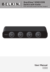
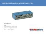
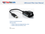
K304x-K308 Secure KM Switch User Manual User Manual Models covered in this user manual: K304 - Secure 4-port KM Switch w/audio K304E - Secure 4-port KM Switch w/audio and DPP K308 – Secure 8-port KM Switch w/audio Rev: 2.9 Doc No: HDC06147 4 & 8 port Secure KM Switch User Manual Table of Content Record of Revisions Rev Date Description of changes Introduction ....................................................................................... 2 2.4 June 19, 2012 Added K308 device What is KM? ....................................................................................... 2 2.5 July 9, 2012 Web based configuration, function keys Package Contents............................................................................... 2 2.6 Sept 19, 2012 Web based configuration process and default settings updated 2.7 Oct 14, 2012 Changed pre-config. shortcuts (added F11) 2.8 April 4, 2013 Removed PS/2 from K308 2.9 July 31, 2015 Images and text updated Security Features ............................................................................... 3 Operational Features ......................................................................... 4 What is Virtual Display Technology (VDT)?........................................ 5 Equipment Requirements .................................................................. 6 Safety Precautions ............................................................................. 7 Front Panel Features .......................................................................... 8 Rear Panel Features – K304E ............................................................. 9 Tamper Evident Labels ..................................................................... 10 Before Installation............................................................................ 13 Installation ....................................................................................... 14 Typical System Sketch – K304E ........................................................ 16 Driver Installation............................................................................. 20 Operation ......................................................................................... 21 DPP Operation.................................................................................. 22 Troubleshooting Guide .................................................................... 24 Copyright and Legal Notice .............................................................. 27 1 4 & 8 port Secure KM Switch User Manual Introduction Package Contents Thank you for purchasing this HSL Secure KM Switch. This KM Switch is designed for use in secure defense and intelligence environments across wide security gaps. This 3rd Generation Secure KM Switch offers optical data diode per channel. Optical data diodes are used to prevent data transfer between connected computers running at different security levels even if these computers attempts to attack the KM. This product provides the highest security safeguards and features that meet today’s and will meet future cyber prevention requirements. Inside product packaging you will find the following: This User Manual provides all the details you’ll need to install and operate your new product, in addition to troubleshooting guidance— in the unlikely event of a problem. What is KM? There are many cases where one computer user needs to work simultaneously with few computers. In some cases users are having multiple displays attached to these multiple computers. The challenge is how a single user can interact with multiple computers having multiple displays. KMs would not do a good job for these users as they were designed to switch displays as well. KM switch is a device that switches a single set of keyboard and mouse between multiple computers. KM switch is essentially a KM switch without the video switching - all displays are continuously connected to their respective computers. 2 HSL Secure KM Switch unit 12V 1.5 A wall-mounted power Supply (K304x models) or AC power cable (K308 model) Important: This product is equipped with always-on active anti-tampering system. Any attempt to open the product enclosure will activate the anti-tamper triggers and render the unit inoperable. If the unit’s enclosure appears disrupted or if all the channelselect LEDs flash continuously, please remove product from service immediately and contact HSL Technical Support. 4 & 8 port Secure KM Switch User Manual Security Features USB Ports Protection HSL Secure KM Switch is the most advanced and secure commercially available KM Switch available today. Below is a summary of some of the security features incorporated into the product. Console USB ports are protected from the use of storage and other unsafe USB devices through strong filtering (independent of computer protection means). Unqualified devices are rejected when connected to the Switch. Only mouse and keyboard data are passed through. Unidirectional Data Paths Optical diodes used to enforce unidirectional data flow from the peripheral devices to computers preventing potential leakage paths between computers even in the severe threat of two infected computers attacking the KM. No Shared Resources Heavy-duty Steel Enclosure HSL Secure KM Switches uses thick steel components to protect the product from physical tampering and to minimize radiated electromagnetic emissions that can be snooped or intercepted. Active Always-On Anti-Tamper This KM Switch designed to securely operate even when peripheral devices are vulnerable to signaling attacks. This KM Switch does not allow computer access to any shared resource and does not share controllable power sources. Active chassis anti-tamper system prevents the KM electronic circuitry from being accessed and tampered with by permanently disabling the product once tampering is detected. Dedicated Processors for Emulation Holographic Tamper-Evident Labels The Switch features a dedicated processor per computer port to emulate peripheral devices. This keeps each computer running on different security levels physically separated and secure at all times, and prevents any unintended data leakage between computers. Four serially numbered holographic security tamper-evident labels are placed on the enclosure surface to provide a visual indication if the Switch has been opened or compromised. Non-Reprogrammable Firmware The Switch features custom firmware that is not reprogrammable, preventing the ability to remotely attack the KM control logic. Dedicated Peripheral Port (K304E) HSL patented Dedicated Peripheral Ports enables secure use of CAC or smart-card readers leveraging security. Common Criteria Listing The Switch is listed by the Common Criteria organization. 3 4 & 8 port Secure KM Switch User Manual Operational Features The HSL Secure KM Switch was designed with the user in mind for today’s IT environment. Below is a summary of some of the features incorporated into the Product. Virtual Display Technology (VDT) VDT allows the KM to switch automatically between computers once mouse cursor crosses display borders. Seamless switching between multiple computers with cusrsor movement. Support for multiple head Product can be easily configured to support dual, triple and up to 16 head computers through signed software driver. Note that single head installation does not need any software installation. Extensive administrator setup options Administrator mode provides many customized settings from display arrangement, size to cursor speed and acceleration. Dedicate Peripheral Port (K304E only) HSL K304E Secure KM Switch products supports parallel switching of wide set of user authentication devices including CAC, smart-card and biometric readers. Audio Support The KM Switch support audio out switching. Microphone switching not supported to prevent analog leakages through audio ports. KM Extenders Support HSL Secure KM Switch supports most copper and fiber KM extenders connected to the console port. 4 4 & 8 port Secure KM Switch User Manual What is Virtual Display Technology (VDT)? Virtual Display Technology (VDT) is implemented in HSL Secure KM switches series to enable seamless cursor and keyboard switching between multiple displays. VDT allows administrators to configure any desired displays configuration with same or different size and resolution. User simply moves mouse cursor across neighboring displays to switch between connected computers. Refer to the example in the figure at the right side. Assume that computer #1 is connected to the left display, computer #2 is connected to the top display, computer #3 is connected to the center bottom display and computer #4 is connected to the display at the right side. In this example all four displays are identical. VDT allows the user to move the mouse cursor across the four displays while automatically switch the shared peripherals based on the current cusrsor location. For example when the user moves the cursor from the left display to the center bottom display, the KM identifies the display boarder crossing between these two displays and switches the KM to computer #3. HSL VDT is now further enhanced with the inclusion of pointing device drivers to support dual, triple and up to 16 head computers. With this technology user workstation may be integrated with any combination of single, dual, triple and quad head computers. VDT Configurator software enables the user administrator to easily configure any set of display sizes, resolutions, geometry and physical arrangements. 5 4 & 8 port Secure KM Switch User Manual Equipment Requirements Cables It is highly recommended to use HSL Cable Kits for product to ensure optimal security and performance. One Cable Kit is required per connected computer. Operating Systems Product is compatible with devices running on the following operating systems: Notes: a. Console USB keyboard and mouse ports are switchable, i.e. you can connect keyboard to mouse port and vice versa. However, for optimal operation it is recommended to connect USB keyboard to console USB keyboard port and USB mouse to console USB mouse port. b. Console USB mouse port supports Standard KVM Extender composite device having a keyboard/mouse functions. c. For security reasons products do not support wireless mice. In any case do not connect wireless mouse to product. • Microsoft® Windows® PS/2 Mouse and Keyboard console ports • Red Hat®, Ubuntu® and other Linux® platforms • Mac OS® X v10.3 and higher. The product console PS/2 keyboard and mouse ports are compatible with standard PS/2 keyboards and mice. USB Keyboard console port User Audio Devices The product console USB keyboard port is compatible with Standard USB keyboards. Product is compatible with the following types of user audio devices: Stereo headphones; Amplified stereo speakers. Notes: a. For security reasons products do not support wireless keyboards. In any case do not connect wireless keyboard to product. b. Non-standard keyboards, such as keyboards with integrated USB hubs and other USB-integrated devices, may not be fully supported due to security policy. If they are supported, only classical keyboard (HID) operation will be functional. It is recommended to use standard USB keyboards. USB Mouse console port The product console USB mouse port is compatible with standard USB mice. 6 Note: In any case do not connect a microphone to product audio output port including headsets. DPP Port (K304E) The product operates with authorized USB devices plugged into the console DPP Port, such as USB smart-card reader or Common Access Card (CAC) reader. Programming Cable In order to use HSL’s external configuration tool it is required to purchase and use HSL USB Type-A to USB Type-A Programming cable (1.8 m). 4 & 8 port Secure KM Switch User Manual Safety Precautions Please read the following safety precautions carefully before using the product: Before cleaning, disconnect the product from DC or AC power. Be sure not to expose the product to excessive humidity. Be sure to install the product on a clean secure surface. Do not place the DC/AC power cord in a path of foot traffic. If the product is not used for a long period of time, remove the product’s wall-mount power supply from the mains jack. If one of the following situations occurs, get the product checked by a qualified service technician: The product’s power supply is overheated, damaged, broken, causes smoke or shortens the mains power socket. Liquid penetrates the product’s case. The product is exposed to excessive moisture or water. The product is not working well even after carefully following the instructions in this user’s manual. The product has been dropped or is physically damaged. 7 The product has obvious signs of breakage or loose internal parts. The product should be stored and used only in temperature and humidity controlled environments as defined in the product’s environmental specifications. The wall-mount power supply used with this product should be the model supplied by the manufacturer or an approved equivalent provided by HSL or an authorized service provider. The use of improper power source will void product warranty. 4 & 8 port Secure KM Switch User Manual Front Panel Features 2 4 3 5b 1 5a 1 – Steel enclosure 2 – DPP (Dedicated Peripheral Port) Freeze push-button and Status LED 3 – DPP channel select LEDs 4 – Channel Select push-buttons and LEDs 5a-5b – Holographic Tamper Evident Labels Note: - 8 K304 is identical except for not having DPP freeze LEDs & button K308 is identical except for having 8 channel select push buttons and not having DPP freeze LEDs & button 4 & 8 port Secure KM Switch User Manual Rear Panel Features – K304E 3 1 4 2 5 6 8 7 9 9 Console ports: Computer group ports: 1 DPP port 5 Computer Keyboard/Mouse USB jack 2 Audio console output 3.5 mm stereo jack 6 Computer audio input jack 3.5 mm stereo 3 USB Mouse & Keyboard jack 7 Computer DPP (USB) port 4 PS/2 Mouse & Keyboard jack 8 Power port 9 Holographic Tamper Evident Labels Note: - 9 K304 is identical except for not having DPP ports in console and computer areas K308 is identical except for having 8 computer areas and not having DPP ports in console and computer areas nor PS/2 ports in console area 4 & 8 port Secure KM Switch User Manual Tamper Evident Labels Active Anti-Tampering System HSL Secure KM Switch uses four holographic tamper evident labels to provide visual indications in case of enclosure intrusion attempt. These labels indicate white dots or the text “VOID” once removed. When opening product packaging inspect the four tampering evident labels. HSL Secure KM Switch is equipped with always-on active antitampering system. If mechanical intrusion is detected by this system, the Switch will be permanently disabled and LED will blink continuously. If for any reason one or more tamper-evident label is missing, appears disrupted, or looks different than the example shown here, please call HSL Technical Support and avoid using that product. HSL Holographic Tampering Evident Label 10 If product indication tampered state (all LEDs blinking) - please call HSL Technical Support and avoid using that product. 4 & 8 port Secure KM Switch User Manual Product Specifications Enclosure Steel metal enclosure Power Requirements K304x: 12V DC, 1.5A (maximum) power adapter with center-pinpositive polarity K308: Internal AC to DC power supply. Power consumption 0.2A @110V maximum. Console Mouse Input - USB Type-A female connector - PS/2 Mini-DIN 6 pin female connector (K304x only) Console DPP Input USB Type-A jack (K304E only) Console Audio Out 3.5mm stereo jack CPU Keyboard/Mouse Ports USB Type-B jack AC Input 100 to 240VAC CPU DPP Ports USB Type-B jack (K304E only) No. of Secure Channels K304x – 4 CPU Audio Input 3.5mm stereo jack K308 - 8 Port Selectors push-buttons 4/8 (model pending) 1 LED Indicators 4/8 Channel selected and 4 for DPP (model pending) Up to 4 displays per computer area: (Special driver must be installed) K304x: up to 16 supported displays K308: up to 32 supported displays User Channel Selection Methods No. of Users Supported Maximum number of Supported displays per Computer Maximum total number Administrator Settings of transitions 100 Console Keyboard Input - USB Type-A female connector - PS/2 Mini-DIN 6 pin female connector (K304x only) Front panel push-buttons VDT (cursor navigation) Keyboard shortcut keys - Display physical size - Display resolution X - Display resolution Y - Display orientation (Portrait / Landscape) - Display head# (1st, 2nd …16th) 11 4 & 8 port Secure KM Switch User Manual - Display location (coordinates) - Mouse speed (1-10) - Mouse acceleration (1-10) - VDT Enable / Disable - Prevent transition while dragging feature Enable / Disable Operating Temp 32° to 104° F (0° to 40° C) Storage Temp -4° to 140° F (-20° to 60° C) Humidity 0-80% RH, non-condensing Dimensions K304x: 320 (W) x 130 (D) x 52 (H) mm / 12.8 (W) x 5.2 (D) x 2 (H) inches K308: 441 (W) x 174 (D) x 46 (H) mm / 17.64 (W) x 6.96 (D) x 1.84 (H) inches Weight K304x: 2.08 Kg. (1.32 lbs.) K308: 2.55 Kg. (5.61 lbs.) Security Accreditation Common Criteria certified Product design life-cycle 10 years Warranty 2 years 12 4 & 8 port Secure KM Switch User Manual Before Installation Unpacking the Product Before opening the product packaging, inspect the packaging condition to assure that product was not damaged during delivery. When opening the package, inspect that the product Tamper Evident Labels are intact. Where to locate the Product? The enclosure of the product is designed for desktop or under the table configurations. An optional Mount Kit is available. Product must be located in a secure and well protected environment to prevent potential attacker access. Consider the following when deciding where to place product: Product front panel must be visible to the user at all times. The location of the computers in relation to the product and the length of available cables (typically 1.8 m) Warning: Avoid placing cables near fluorescent lights, airconditioning equipment, RF equipment or machines that create electrical noise (e.g., vacuum cleaners).). 13 Important: 1. If the unit’s enclosure appears disrupted or if all channelselect LEDs flash continuously, please remove product from service immediately and contact HSL Technical Support at http://highseclabs.com/support/case/. 2. Do not connect product to computing devices: a. That are TEMPEST computers; b. That include telecommunication equipment; c. That include frame grabber video cards d. That include special audio processing cards. 4 & 8 port Secure KM Switch User Manual Installation Connecting devices to product console Product requires connection of all devices and computers prior to powering it up. classical keyboard (HID) operation will be functional. It is recommended to use standard USB keyboards. 4. Console USB mouse port supports Standard KVM Extender composite device having a keyboard/mouse functions. 2. Connecting the Computers Note: some devices such as user display would not be recognized if connected after product is already powered up. See figures above for connector locations. Connect user display/s to computers. Mark which display is coupled with which computer. It is also recommended to mark which computer is coupled with which channel. Connect user keyboard and mouse to console keyboard and mouse ports. Connect headphones/speakers to console audio out port (optional). If the computer uses a smart card reader/USB device, connect the smart card reader/USB device to the console DPP port (optional, model pending). Note: 1. If the number of product channels is larger than the number of sources used, make sure the computers are connected in a row starting from computer #1. For example, if there are 3 channels used, connect computers to channels #1, #2 and then #3. 2. The USB cable must be connected directly to a free USB port on the computer, with no USB hubs or other devices in between. Notes: 1. Console USB mouse and keyboard ports are switchable, i.e. you can connect keyboard to mouse port. However, for optimal operation it is recommended to connect USB keyboard to console USB keyboard port and USB mouse to console USB mouse port. 2. For security reasons products do not support wireless keyboards. In any case do not connect wireless keyboard to product. 3. Non-standard keyboards, such as keyboards with integrated USB hubs and other USB-integrated devices, may not be fully supported due to security policy. If they are supported, only 14 Using USB cables, connect each computer to the USB type B port in "computer interface ports" area on product. If computer uses audio output, e.g. speakers/headphones, connect audio cable from its audio output port to the corresponding audio input port on product. If the computer uses a smart card reader/USB device, connect a USB cable between the DPP-enabled computer and the corresponding DPP port on product. 3. Power up Connect DC power supply or AC power cord (model pending). Power up user display/s. Select through display setup menu the appropriate video input if applicable. Power up the connected computers. Power up the product. 4 & 8 port Secure KM Switch User Manual When you power up your computers, the product emulates display, mouse and keyboard on each port and allows your computers to boot normally. You should be able to move the mouse cursor on the primary display connected to computer #1. Check to see that the keyboard and mouse are working properly on each computer. Repeat this check with all occupied ports to verify that all computers are connected and responding correctly. If you encounter an error, check your cable connections for that computer and reboot. If the problem persists, please refer to the Troubleshooting section in this User Manual. DPP Installation (Optional, K304E only) The following process can be performed before or after power up. If computer and KM Switch supports user authentication device, connect another USB cable for the DPP function. DPP USB cable can be connected to any free USB port in the computer. Note: Do not connect DPP USB cable if user authentication device is not needed. Secure KM Switch automatically detects this cable to program DPP port selection logic accordingly. If not all of the channels are having DPP function (some computers not connected through DPP cable) – make sure that channel #1 is using DPP – switch channels if needed. When KM is powered on - once the connected device is qualified and ready for use – the DPP status LED should illuminate green. If connected device cannot be detected by the Secure KM Switch then DPP status LED will not illuminate at all. Device must be fully compliant with USB 1.1 or USB 2.0 standard. 15 Possible reasons: Non standard USB device Device only operating in USB 3 mode Device not operating Use other devices instead. If the device is detected but does not match DPP qualification specification – device will be rejected as indicated by status LED illuminating steady red. 4 & 8 port Secure KM Switch User Manual Typical System Sketch – K304E 16 4 & 8 port Secure KM Switch User Manual Administrator Setup Now that the Secure KM Switch is connected and powered on it is good opportunity to setup some essential operational settings. The first and most important setting of the KM is the display positioning. It is essential that the KM switch configuration will match the actual positioning on the displays. There are two ways to configure the KM switch with the actual display setup: Select one of the predefined setups Create a configuration file and load it to the KM Selecting one of the predefined setups It is also possible to load one of the default settings available in the KM non-volatile memory. To select a default configuration type on the console keyboard: Control + Control + F11 + Fx (see numbers in the figure to the right). Additional settings can be accessed through Control + Control + F11 + x + y. The configuration loaded will include in additional to the displays arrangement: - All displays are 1920 x 1200 resolution, same size (26” diagonal) Mouse acceleration is set to 6 Mouse speed is set to 5 VDT is enabled Prevent transition while dragging feature is Enabled Creating a configuration file In case the required configuration does not appear on the predefined configurations list the administrator can create a configuration file using HSL’s KM Web Configuration Tool and load it to the KM. for more information about this option please refer to HSL’s Web Configuration Tool user manual. 17 For example: typing Control + Control + F11 + F5 will set the left display to computer #1 (single-head), second display to computer #2 (single-head), third display to computer connected to port #3 (dualhead primary output) and the forth display to same computer secondary display output. 4 & 8 port Secure KM Switch User Manual 18 4 & 8 port Secure KM Switch User Manual Example 1: To select a configuration with two displays 1 above the other. Please type: CTRL | CTRL | F11 | 2 | 5 The KM will start “blinking” between channels. Reboot the device by disconnecting power and the device will boot with the new configuration. 19 4 & 8 port Secure KM Switch User Manual Other Settings Key Combination Name Description Mouse Speed Setting CTRL | CTRL | F11 | r Reset to Factory defaults Constant mouse cursor speed is essential for system usability. Having several systems each with a different cursor “ground speed” is bad for the user. HSL calculates and adjusts the cursor speed across different displays and computers using the geometry and display settings entered by the administrator. Device will reset to factory defaults with all settings and configuration deleted completely. CTRL | CTRL | F11 | f Freeze Disable VDT. Switching between systems will not be possible via mouse movement. CTRL | CTRL | F11 | U Unfreeze Enable VDT. Switching between systems will be again possible via mouse movement. CTRL | CTRL | F11 | + Increase mouse speed Mouse speed increased. will be CTRL | CTRL | F11 | - Decrease mouse speed Mouse speed decreased will be CTRL | CTRL | F11 | d | c Setup mode In the next boot after pressing this key combination the device will boot into setup mode allowing him to communicate with configuration utility. CTRL | CTRL | F12 Last loaded configuration Revert to the last externally loaded configuration (configuration loaded via configuration utility). In addition, the KM settings include a global speed setting with input values between 1 and 10 that can be changed to adjust the cursor speed for all displays. Typical initial setting of cursor speed is 5. After initial use the exact value can be set based on user inputs. VDT Enabled / Disabled Setting It is possible through the VDT enabled / disabled setting to disable the mouse cursor tracking function. Once VDT is disabled – the KM will enable channel selection only through: 1. Front panel push-buttons; 2. Keyboard shortcuts; and: 3. RDC (if connected) This setting is enabled by default. Prevent transition while dragging feature HSL Secure KM offers a unique feature that further improves usability – Prevent transition while dragging. When this feature is enabled, if the user drags an object on one display (while left mouse key pressed), the cursor would not leave that display. The following table describes the keyboard shortcuts available on HSL KM switches: 20 Driver Installation To enable proper KM interaction with computers having multiple head (more than one display), mouse driver software must be installed. Driver can be loaded from HSL web-site. The driver is available in EXE file that installs itself at the target computer. 4 & 8 port Secure KM Switch User Manual Operation Now that you have connected your console and computers to the Switch, it is ready for use. Default channel after power up is channel #1 as indicated by channel select LED #1 illumination. You can select which computer you wish to control by one of the following methods: Default Channel After product boots up, the default active channel will be channel #1. This will be indicated by white color illumination of push-button #1. Product Mapping to Sources Product mapping to sources is indicated by stickers/labels specifying which channel is mapped to which computer. Front Panel Push-Buttons Following power up, the default channel is #1. The user can select any other channel by pressing the appropriate front panel push button. The mouse cursor will be positioned at the center of the selected computer display. The currently selected channel is indicated by white color illumination of the appropriate push-button. 21 Important Security Note: If you are aware of potential security vulnerability while installing or operating this product, we encourage you to contact us immediately in one of the following ways: Web form: http://www.highseclabs.com/support/case/ Email: [email protected] Tel: +972-4-9591191 or +972-4-9591192 Important: If the unit’s enclosure appears disrupted or if all channel-select LEDs flash continuously, please remove product from service immediately and contact HSL Technical Support at http://www.highseclabs.com/support/case/ Important: This product is equipped with always-on active antitampering system. Any attempt to open the product enclosure will activate the anti-tamper triggers and render the unit inoperable and warranty void. 4 & 8 port Secure KM Switch User Manual DPP Operation The product is equipped with DPP port enabling connectivity to external USB-devices such as smartcard reader. Summary of rules that apply to DPP switching: It is assumed that a "connected channel" is when: 1. Product is powered ON 2. The USB device connected to product console is qualified and ready for use, as indicated by the DPP status LED illuminating steady green. 3. The channel DPP port on product is connected via USB cable to a USB port on computer. When the USB device connected to the DPP console port is qualified, the DPP status LED on the front panel would illuminate steady green. o When connecting a USB device that is rejected for security reasons to the product's DPP port, the DPP LED will illuminate steady red and USB device will be inoperable. In such case the USB device must be replaced with a qualified device, either USB smart card or CAC reader. Since channel #1 is the default active channel after power up and in case only some of the channels operate with a USB device, it is recommended to make sure computer #1 is connected to USB device. Once the user switches channels, for example to channel #3, DPP functionality will move to computer #3 and be indicated by channel #3 DPP LED turning steady green. In case user switches to a channel that is not connected to a USB device, the DPP function will remain with the last channel that had DPP connection. 22 Cursor Tracking (VDT Enabled) Following KM power up the cursor will be positioned at the center of the primary display of computer #1. Keyboard and audio will be coupled to the same PC where the cursor is. Once the user moves the cursor to another display, the keyboard and audio will follow to that computer. For more information about VDT see page 6 of this manual. Front Panel Push-Buttons Following KM power up the default channel is 1. The user can select any other channel by pressing the appropriate front panel push button. The mouse cursor will be positioned at the center of the selected computer display. If computer has multiple head then the cursor will be positioned at the center of the primary display. Channel selected is indicated by LED illuminated in the appropriate push-button. Keyboard and audio will follow selected channel. RDC Operation For Remote Desktop Controller operation – refer to the RDC User Manual supplied with the product. Note that when RDC is connected – the Secure KM Switch front panel push-buttons are deactivated. Prevent transition while dragging feature HSL Secure KM offers a unique feature that further improves usability – Prevent transition while dragging. When this feature is enabled, if the user drags an object on one display (while left mouse key pressed), the cursor would not leave that display. This feature prevents the loss of that dragging action while accidentally crossing display border line. 4 & 8 port Secure KM Switch User Manual Feature may be enabled or disabled through the administrator setup. By default this feature is enabled. Cursor Acceleration and Speed Cursor speed and acceleration is a combination of few factors such as display size, resolution and static settings. If current settings are not constant across the different displays or not comfortable – ask your system administrator for assistance. Both cursor acceleration and speed can be set by the administrator to reach comfortable settings. Important Security Note: If you are aware of potential security vulnerability while installing or operating this product, we encourage you to contact us immediately at the following email address: [email protected] 23 4 & 8 port Secure KM Switch User Manual Troubleshooting Guide Important Security Note: If you are aware of potential security vulnerability while installing or operating this product, we encourage you to contact us immediately in one of the following ways: Web form: http://www.highseclabs.com/support/case/ Email: [email protected] Tel: +972-4-9591191 or +972-4-9591192 Important: If the unit’s enclosure appears disrupted or if all channel-select LEDs flash continuously, please remove product from service immediately and contact HSL Technical Support at http://www.highseclabs.com/support/case/ Important: This product is equipped with always-on active antitampering system. Any attempt to open the product enclosure will activate the anti-tamper triggers and render the unit inoperable and warranty void. 24 General Problem: No power - No video output, none of the front panel LEDs are illuminating. Solutions: Check AC cable connection to make sure product receives power properly. Replace cable if needed. If problem persists, contact your system administrator or our technical support. Problem: Product enclosure appears disrupted or all channelselect LEDs flash continuously. Solution: The product may have been tampered with. Please remove product from service immediately and contact Technical Support. 4 & 8 port Secure KM Switch User Manual Keyboard Mouse Problem: Mouse and keyboard are not working (two channels) Problem: Mouse cursor does not switch from primary to secondary display. Solutions: Check that computer USB and video cables are not crossed i.e. computer #1 video is connected to channel #1 while USB keyboard and mouse cables are connected to channel #2. Solutions: Driver supporting multiple displays was not installed or not installed properly on computer. Reinstall driver. Problem: Mouse and keyboard are not working (two channels) Solutions: Problem: Keyboard does not work (all channels) Solutions: Check that the keyboard you are using is properly connected to product. Check that the USB cable between the product and computer is properly connected. Try connecting keyboard to a different USB port on computer. Make sure the keyboard works when directly connected to computer, i.e. the HID USB driver is installed on computer; this may require computer reboot. It is recommended to use standard USB keyboards and not a keyboard with an integrated USB hub or other USBintegrated devices. If the computer is coming out of standby mode, allow up to one minute to regain mouse function. Try a different keyboard. Do not use a wireless keyboard. Check that computer USB and video cables are not crossed i.e. computer #1 video is connected to channel #1 while USB keyboard and mouse cables are connected to channel #2. Problem: Mouse does not work (all channels) Solutions: Check that the mouse you are using is properly connected to product. Check that USB cable between the product and computer is properly connected. Try connecting mouse to a different USB port on computer. Make sure the mouse works when directly connected to computer, i.e. the HID USB driver is installed on computer; this may require computer reboot. It is recommended to use standard USB mice. If the computer is coming out of standby mode, allow up to one minute to regain mouse function. Try a different mouse. Do not use a wireless mouse. Problem: both keyboard and mouse are not working (one channel) Solution: Use computer Device Manager Utility to see product and solve problem. 25 4 & 8 port Secure KM Switch User Manual DPP Problem: DPP is not working (two channels) Solutions: Check that computer USB and video cables are not crossed i.e. computer #1 video is connected to channel #1 while USB device is connected to channel #2. Problem: DPP is not working (all channels) Solutions: Check that the USB device is properly connected to product console. Check that the DPP status LED is steady green. If DPP status LED is illuminated steady red the device is rejected or non-qualified for security reasons. To resolve please connect a USB smart card or CAC reader or contact your system administrator. Problem: DPP is not working (one channel only) Solutions: 26 Check that device is working properly when connected directly to computer. Check that there is a USB cable connected between the computer and the relevant DPP input port on product. 4 & 8 port Secure KM Switch User Manual Copyright and Legal Notice © 2015 High Sec Labs Ltd. (HSL) All rights reserved. PATENTS AND TRADEMARKS This product and/or associated software are protected by copyright, international treaties and various patents. The products described in this manual are protected by multiple patents. This manual and the software, firmware and/or hardware described in it are copyrighted. You may not reproduce, transmit, transcribe, store in a retrieval system, or translate into any language or computer language, in any form or by any means, electronic, mechanical, magnetic, optical, chemical, manual, or otherwise, any part of this publication without express written permission from HSL. HSL Product/s and logo are either trademarks or registered trademarks of HSL. HSL SHALL NOT BE LIABLE FOR TECHNICAL OR EDITORIAL ERRORS OR OMISSIONS CONTAINED HEREIN; NOR FOR INCIDENTAL OR CONSEQUENTIAL DAMAGES RESULTING FROM THE FURNISHING, PERFORMANCE, OR USE OF THIS MATERIAL. The information contained in this document represents the current view of HSL on the issues discussed as of the date of publication. Because HSL must respond to changing market conditions, it should not be interpreted to be a commitment on the part of HSL, and HSL cannot guarantee the accuracy of any information presented after the date of publication. PRODUCT DESIGN AND SPECIFICATION IS SUBJECT TO CHANGES WITHOUT NOTICE This Guide is for informational purposes only. HSL MAKES NO WARRANTIES, EXPRESS OR IMPLIED, IN THIS DOCUMENT. 27 Products mentioned in this document may be registered trademarks or trademarks of their respective owners U.S. GOVERNMENT RESTRICTED RIGHTS The Software and documentation are provided with RESTRICTED RIGHTS. You agree to comply with all applicable international and national laws that apply to the Software, including the U.S. Export Administration Regulations, as well as end-user, end-use and country destination restrictions issued by U.S. and other governments. The information and specifications in this document are subject to change without prior notice. Images are for demonstration purposes only.