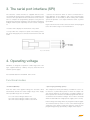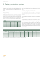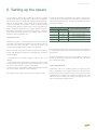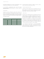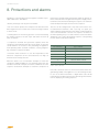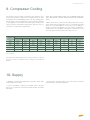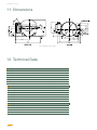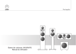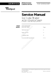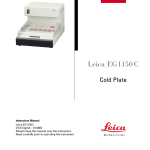
1
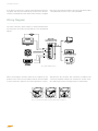
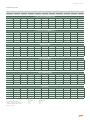
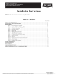
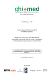
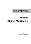
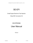
USER MANUAL
GD30FDC
Compressors for mobile applications
12 · 42V Direct Current Compressor
USER MANUAL GD30FDC
INDEX
1. About the Product
2. Wiring and connections
3. The Serial Port Interface (SPI)
4. Operating voltage
5. Battery protection system
6. Setting up the speed
7. Programming the electronic driver
8. Protections and alarms
9. Compressor cooling
10. Supply
11. Dimensions
12. Technical data
1. About the product
Many vehicles for transportation of goods or recreation, such
as trucks, caravans, boats, cars, etc. are often equipped with
cooling appliances. The compressors for such mobile applications must be designed to operate from a low voltage DC
power supply. These compressors must also be compact in
their dimensions, highly reliable and yield high performances.
GD30FDC is Cubigel’s answer to the needs of users requiring comfort and reliability in their travelling, either on holidays,
at work or in any other circumstance where a DC powered
refrigerator is utilised. The GD30FDC is designed to operate
silently, efficiently and reliably even up to angles of tilt of 30º,
and works with the environmentally friendly refrigerant R134a.
Its design is based on Cubigel’s “D” series, which has been
successfully present in the market since 1984, and has had
sales of 15 million units.
GD30FDC compressor is not designed for off-road mobile
applications. If you are interested in this type of mobile applications, it has to be specifically approved by Cubigel Compressors.
GD30FDC can be powered at any voltage within the 12 to 42V
DC range, and is designed for capillary tube expansion. Each
unit is supplied with a dedicated electronic driver (FDC1),
which features all the protections for both the battery and the
driver itself, including the compressor motor. The driver automatically adjusts itself to the voltage of the power supply.
Evaporation temperature range: -30ºC to +10ºC.
Condensation temperature range: up to 65ºC. Pull-down
peak: 70ºC.
Ambient temperature range: -10 to 55ºC (65ºC at starting).
USER MANUAL GD30FDC
In case of ambient temperature lower than 0ºC, an oil heater
will be needed.
The electronic control unit FDC1 is supplied with the exclusive
Serial Port Interface (SPI), featuring a RJ11 telephone type
connector. SPI allows the electronic driver to be connected
to a computer for programming purposes using the FxC programming package (hardware and software, provided by Cubigel under request), and allows the communication with an
Electronic Integral Manager of the appliance (EIM), and making the compressor work in slave mode.
FDC1 electronic driver includes Smart Speed® as programming option, which is a plug-in system for automatically selfadapting compressor speed to current thermal load.
Smart Speed® reduces the number of thermostat cycles by
minimizing compressor speed, enlarging on-time at every
thermostat cycle, so that start/stop energy loses are substantially reduced. Lowest speed yields also highest evaporating temperature, and so highest C.O.P and lowest energy
consumption. Pull-down is done at maximum programmed
speed, so pull-down time is very short with respect to fixed
speed systems. No design parameters neither of the compressor nor the appliance are required to be programmed, so
Smart Speed® can be easily used in all appliances with no
design efforts.
FDC1 electronic driver includes also Sleep and Sleep Energy Saving as programming option, which is a plug-in system specially conceived for mobile air conditioners avoiding
any other electronic device. Sleep and Sleep Energy Saving
makes the air conditioner work for four hours since start-up.
Sleep Energy Saving makes the compressor run at maximum
programmed speed during the first hour, when highest cooling capacity is needed, and lowers compressor speed progressively to minimum velocity three hours later. Maximum
comfort and minimum energy consumption is thus achieved.
GD30FDC starting capability is as low as 10V under any balanced pressure. It also admits a certain remaining differential
pressure when thermostat off-time is abnormally short. For
improving even more the starting capability, FDC1 electronic
driver is supplied with a 3 minutes minimum thermostat offtime. The delay is a programming option which can be easily
removed if no delay is preferred for any reason.
FDC1 also includes a 1 second filter at the thermostat input
to prevent the appliance from wrong operation due to typical
micro switching produced by vibrations in those appliances
that fit tilt switches at the thermostat circuit. So, analogical
filtering is not needed.
USER MANUAL GD30FDC
2. Wiring and Connections
General rules
GD30FDC must always be powered through the dedicated
electronic driver FDC1, which is supplied with the compressor
as a separate device.
The unit is protected against damage caused by wrong polarity of the supply,. The compressor will not run correctly if it’s
wrongly connected.
NEVER CONNECT THE COMPRESSOR’S HERMETIC PINS
(FUSITE) TO THE TERMINALS OF A BATTERY OR ANY OTHER DC OR AC SOURCE DIRECTLY.
“-“ POWER INPUT TERMINAL OF THE ELECTRONIC DRIVER
SHOULD BE REFERRED TO THE CHASSIS OF THE VEHICLE
AS WELL AS THE APPLIANCE FRAME*
DO NOT TRY TO FIT AN ELECTRONIC DRIVER OTHER THAN
THE FDC1. THE COMPRESSOR WILL NOT OPERATE AND
IRREVERSIBLE DAMAGE MAY OCCUR.
A FUSE MUST BE PLACED BETWEEN THE “+” POLE OF
THE BATTERY OR DC POWER SUPPLY AND THE “+” POWER INPUT TERMINAL OF THE ELECTRONIC DRIVER*
The FDC1 driver is directly connected to the battery poles as
well as to the compressor pins. It checks battery voltage and
adjusts itself to the voltage value for proper compressor operation, or switches itself off if the battery voltage is not adequate. The driver also controls the compressor speed.
12V SYSTEMS: 30A FUSE
24V SYSTEMS: 15A FUSE
42V SYSTEMS: 10A FUSE
ALWAYS RESPECT THE POLARITY OF THE BATTERY WITH
THE POWER INPUT TERMINALS OF THE ELECTRONIC
DRIVER
In some special vehicles chassis is connected to “+” terminal of the battery instead of “-“ terminal (positive reference
systems). In such cases “+” should be understood as “-“ and
vice-versa.
In systems powered by a variable DC source, the fuse should
be selected following the rules above mentioned, considering
the maximum voltage at the variable DC Source.
Voltage drop in the power leads
To avoid excessive voltage drop in the leads, their length and
cross section must be related to the voltage supply as indicated in Table 1.
Cross section
mm2
Rated Operating Range
12 - 14 V
24 - 28 V
36 - 42 V
2.5
1.5
3
4.5
4
2.5
5
7.5
6
4
8
12
10
6
12
18
Table 1: Maximum length of leads (m)
USER MANUAL GD30FDC
If any kind of connector or switch is placed between the battery poles and the power terminals of the electronic driver, its
resistance should be less than 10mΩ. If the resistance is higher
than 5mΩ, the maximum length of the wires indicated in Table
1 should be halved or the cross section doubled.
Wiring Diagram
The FDC1 electronic driver features a terminal board where
all connections are made. The terminal lay out is described in
Figure 1:
Fig. 1. FDC1 Wiring scheme
When connecting the electronic driver to the compressor, any
position of the connector is possible under an electrical point
of view. However, in practice, the vertical position is not pos-
sible because the electronic box cannot be assembled. The
connector should be rotated 120º clockwise or counter clockwise with respect to the vertical position as shown below.
Fig. 2. Connection of the FDC1 electronic driver to the compressor
USER MANUAL GD30FDC
3. The serial port interface (SPI)
The electronic control unit FDC1 is supplied with the exclusive Serial Port Interface (SPI), featuring a RJ11 telephone type
connector. This port allows the electronic driver to be connected to a computer for programming purposes using the FxC
programming package (hardware and software) provided by
Cubigel under request. Optionally, the SPI can be configured
to:
• Connect the electronic driver as slave to an Electronic Integral Manager of the appliance with serial communication
capabilities (Rx, Tx and COM), to allow working with variable
speed. SPI provides a 5 V output, limited to 25mA, to power
up the EIM.
Figure 3 Shows the RJ11 male connector which can be plugged
to the SPI and the usage of each terminal in it.
• Install a LED to display the intervention of any alarm.
• Set up either the compressor speed or the battery protection level, through physical connections between IN1, IN2 and
COM.
Fig. 3. SPI terminals
4. Operating voltage
GD30FDC is designed to operate in a wide range of DC voltages, supplied either by a battery or by any other kind of filtered DC power supply.
DC VOLTAGE SUPPLY ALLOWED: 10V to 42.4V
Functional modes
• Standard (Default):
• Special (programming option):
From the value of the applied voltage, the electronic driver
automatically decides the rated voltage range of the supply.
Three possible ranges are considered:
The compressor can be powered by a variable DC source as,
for instance, a photovoltaic panel, in which the output voltage strongly depends on the intensity of sunlight radiation. In
these special cases the driver should be programmed with rated, minimum and maximum voltages. These values should be
within the allowable DC voltage power supply (10 V to 42.4V).
12 to 14V: actual voltage is below 17V
24 to 28V: actual voltage is within 17 and 33V
36 to 42V: actual voltage is within 33 and 42.4V
Rated voltage and voltage limits are programmed by the appliance manufacturer by means of a PC connected through the
serial port to the driver’s Serial Port Interface, using the FxC
programming package provided by Cubigel under request.
USER MANUAL GD30FDC
5. Battery protection system
There is a protection system for the battery that prevents the
compressor from operating if the available voltage becomes
too low. The battery protection level should be set up as following:
In Table 2, ΔV is the difference between cut-out and cut-in,
that is, the cut-in value is the result of adding ΔV to the cut-out
value.
• Externally, using COM, IN1 and IN2 of SPI:
• By programming:
Voltage limits for battery protection can be freely set, by the
customer for every system (12-14V, 24-28V, 36-42V or special)
by means of the serial or USB port of a PC connected to the
SPI port of the electronic driver using the FxC programming
package provided by Cubigel under request. In that option cutout and cut-in values must respect the rule defined by Table 2.
· The external battery protection set up option must be previously programmed for external adjustment of the protection
limits.
· Voltage limits are set up by means of a PC through its serial or
USB port connected to the electronic driver SPI. It can be done
by the customer itself using the FxC programming package.
Rated
voltage
range (V)
12-14
min
max
min
max
9,0
12.0
1.0
1.5
24-28
20,0
26.0
2.0
3,0
36-42
34,0
40.0
2.0
3.0
Special
9,0
40.0
1.0
3.0
Cut-out (V)
· This option prevents from the possibility of setting up the
speed externally using COM, IN1 and IN2 of SPI as defined
in point 6.
ΔV
Table 2. Limits of battery protection parameters
· The cut-out (battery voltage at which the driver stops operating) and the cut-in (battery voltage at which driver re-starts
operation after a cut-off) values are set up by connecting the
SPI connector terminals IN1 and IN2 to COM. According to the
connection made, four protection levels can be selected as
shown in Table 3.
Rated operating voltage range
Protection limits (V)
Protection
level
Connection to COM
IN1
12-14 V
IN2
cut-out
24-28 V
cut-in
cut-out
36-42 V
cut-in
cut-out
cut-in
Standard
0
0
10.0
11.5
22.0
24.5
36.0
38.5
Low
1
0
9.0
10.5
20.0
22.5
34.0
36.5
High
0
1
11.0
12.5
24.0
26.5
38.0
40.5
Very high
1
1
12.0
13.5
26.0
28.5
40.0
42.5
Table 3. IN1, IN2 and COM connection for battery protection set up 0=open connection; 1=shortened
USER MANUAL GD30FDC
6. Setting up the speed
It is possible to operate the compressor at fixed or variable
speed under different running modes, options and parameters.
The electronic driver is supplied by Cubigel with standard running mode and external control of the speed, with minimum
speed of 1,500 rpm and maximum speed 3,500 rpm. Default
running mode, options and parameters can be changed to optimize compressor performance for a given appliance, by programming, connecting a PC to the SPI by means of the FxC
programming package provided by Cubigel under request.
Running modes and options are:
• Standard mode:
Compressor speed is a fixed programmed value or switched
externally from programmed minimum and maximum value in
four steps. The switch should be connected to the SPI and
should remain plugged during compressor operation.
When setting up a fixed speed, maximum speed can be limited
by the available battery voltage in the following way, maximum
speed would be:
· 1,500 rpm when the battery voltage is equal to the cut-in
voltage.
· Programmed fixed speed when the battery voltage is equal
to or greater than the maximum nominal voltage (14V, 28V and
42V for 12V, 24V and 42V systems respectively).
· A linear function of the battery voltage in the range between
the cut-in and the maximum nominal voltages.
This option is particularly useful for eutectic plates systems.
If external switching is programmed, the speed is set up by the
connection of the SPI terminals IN1 and IN2 to COM for minimum and maximum speeds, and two intermediate velocities
according to Table 4:
Connection to COM
Speed of the motors (rpm)
IN1
IN2
0
0
Smin
1
0
Smin + 1/3 (Smax-Smin)
0
1
Smin + 2/3 (Smax-Smin)
1
1
Smax
Table 4. External selection of the velocity 0=Open connection; 1=Shortened
External speed set up option must be previously programmed
for external adjustment of its minimum (Smin) and maximum
(Smax) limits.
External switching prevents from the possibility of setting up
the battery protection externally using COM, IN1 and IN2 of
SPI as defined in point 5.
• Smart Speed® mode:
Compressor will run at variable speed at its highest performance depending of the actual thermal load. The speed can
be limited by a fixed programmed value and even more by the
available battery voltage as described in standard mode. The
speed can also be limited by external switching in the same
way as described in standard mode.
USER MANUAL GD30FDC
NO SWITCH (MANUAL I/O, TILT, ETC.) IS ALLOWED TO BE
CONNECTED IN SERIES WITH THE THERMOSTAT.
If off sleep mode is selected, the appliance will run continuously at selected fixed speed Smin or Smax.
IF ELECTRONIC THERMOSTATS ARE TO BE FIT, AVOID
THOSE THAT INCORPORATE MANUAL I/O SWITCH AND/OR
STARTING DELAY.
• Sleep Energy Saving mode:
• Sleep mode:
Compressor will run during four hours after start-up. The
speed can be limited by a fixed programmed value and even
more by the available battery voltage as described in standard
mode. The speed can also be limited by external switching in a
similar way as described in standard mode, Cubigel Compressorsording to table 5:
Connection to COM
IN1
IN2
Speed of the
motors (rpm)
Sleep mode
0
0
Smin
off
1
0
Smin
on
0
1
Smax
off
1
1
Smax
on
Table 5. External selection of the velocity 0=Open connection; 1=Shortened
Compressor will run during four hours. During first hour compressor will run at selected speed. During next three hours
speed will decrease up to 1,500 r.p.m. Programming Sleep Energy Saving is done in the same way as Sleep.
• Slave mode:
Under this mode, variable speed is controlled by an Electronic
Integral Manager of the appliance (EIM) permanently connected to the electronic driver FDC1 through the SPI, using its serial communication capabilities. The EIM reads the actual temperature inside the appliance, compares it with the set point
temperature, and decides if the compressor should operate
or not, and if so, at which speed. The EIM communicates how
the compressor should operate and, eventually, records any
abnormal circumstance that might occur. For details about the
communication protocol, please, contact Cubigel.
IF ANY VARIABLE SPEED MODE IS TO BE PROGRAMMED,
CHECK CAREFULLY FOR TUBE, CONDENSER AND EVAPORATOR RESONANCES. NATURAL FREQUENCIES SHOULD
BE 75 Hz UP TO AVOID VIBRATIONS.
USER MANUAL GD30FDC
7. Programming the electronic driver
In order to program the electronic driver FDC1, a personal computer together with the FxC programming package are required
(provided by Cubigel under request). To this purpose, perform
the following steps:
1. Install the programming software, following the instructions
of the wizard.
2. Connect the programming interface to a PC using a serial/
serial or USB/serial cable supplied with the hardware.
3. Power on the programming interface using the AC/DC
adapter supplied with the hardware.
4. Connect the FDC1 electronic driver to the programming interface using the double RJ11 cable supplied with the hardware.
5. Run the programming file FDC.exe.
6. From the top menu, load an existing configuration and go to
step 9, or go through step 7.
7. Select the running mode, options and parameters, between:
7.1 Standard mode.
7.1.1 Select maximum fixed speed and enter a value within
1,500 and 3,500 r.p.m. as described in point 6, if desired select
speed limited by available battery voltage, or
7.1.2 Select external switcher connected to SPI and enter low
and high speed values within 1,500 and 3600 r.p.m. as described in point 6. External speed selection is incompatible with
external battery protection (step 8.2).
7.2 Smart Speed® mode. Select maximum fixed speed or external switcher connected to SPI and proceed as described in
7.1.1 or 7.1.2 respectively.
7.3 Sleep and Sleep Energy saving modes. Select maximum
fixed speed or external switcher connected to SPI and proceed
as described in 7.1.1 or
7.4 Slave mode
8. Select the battery protection mode and the protection parameters from:
8.1 Internal protection: choose between normal and special
voltage systems.
8.1.1 For normal voltage systems, enter cut-out, cut-in and
maximum voltage values for every voltage system, accounting
for the limits shown in Table 2 of point 5.
8.1.2 For special voltage systems, enter cut-out, cut-in and
nominal and maximum voltage values accounting for the limits
shown in Table 2 of point 5.
8.2 External protection. Protection values are shown in Table
3 of point 5. External protection is incompatible with external
speed selection (step 7.2).
9. Select thermostat delay 3 minutes for improved starting.
10. Click “Apply”. The FDC1 electronic driver is now programmed and ready to drive the compressor.
11. From the top menu, save the current configuration if desired.
12. To program another FDC1 unit, plug it in, apply current
configuration or return to step 6 to change configuration.
13. Click exit to finish.
USER MANUAL GD30FDC
8. Protections and alarms
GD30FDC is electronically protected against a number of possible malfunctions and failures:
• Battery discharge: refer to point 5 for details.
• Fan over current: protects the compressor and the electronic
driver against fan over current due to start or running overload,
or short-circuit.
• Starting failure: if the running speed is not achieved during
the starting sequence, the unit stops and retries the start up
after one minute.
• Compressor overload: This protection operates when the
compressor speed drops below the set up speed, or when the
current drawn in is excessive, thus preventing the appliance
from operating under overload conditions, causing refrigerating overload or compressor failure.
• Electronic driver overheat: In case the temperature of the
electronic components of the control becomes too high, an
internal sensor will stop the unit.
When the alarm is on, ten automatic attempts to restart the
compressor will be available. In case of battery protection, the
number of automatic attempts to restart is unlimited. Once the
sequence of automatic attempts to restart the compressor is
finished, the unit will remain permanently unable to operate until it is switched off and on again from the power supply. The intervention of the thermostat during the sequence of automatic
restart attempts interrupts and resets the sequence.
The SPI can be configured in a way that a LED can be connected between terminals 3 and 4 (see Fig. 2 in point 3) in
order to display the intervention of any alarm, and to identify its
cause. The visualisation consists of a sequence of flashes of
the LED repeating every 5 seconds, until the cause of the alarm
disappears. The code of the flashing sequence corresponding
to each alarm is indicated in Table 6:
No. of flashes
Type of fallure
1
battery protection
2
fan over current
3
starting failure
4
compressor overload
5
electronic driver overheat
6
internal error
Table 5. Alarm codification
If the FDC1 electronic driver is connected to an Electronic Integral Manager (EIM) of the appliance as a slave through the SPI,
in case of an alarm intervention, a digital alarm code will be
transmitted to the EIM, which in turn will manage the information for displaying and acting purposes.
USER MANUAL GD30FDC
9. Compressor Cooling
An adequate heat removal mechanism from both the electronic driver and the compressor is fundamental for an optimal performance and reliability of the unit. The cooling method should be selected depending on the working conditions
of the appliance, with major factors being the compressor’s
velocity and the evaporation temperature, and also, but secondary, the condensation temperature.
r.p.m.
FREE AIR CIRCULATION OVER THE COMPRESSOR AND
THE ELECTRONIC DRIVER MUST ALWAYS BE GUARANTEED.
Table 6 shows the recommended cooling method for a standard condensation temperature of 55ºC. The table should be
taken as a recommendation, as the only way to validate a
design is testing the appliance at the highest evaporation,
condensation and ambient temperature, verifying that the
electronic driver overheat protection does not act.
Evaporation Temperature
-30
-25
-20
-15
-10
-5
0
5
10
1500
Static
Static
Static
Static
Static
Static
Static
Fan
Fan
2000
Static
Static
Static
Static
Static
Static
Fan
Fan
Fan
2500
Static
Static
Static
Static
Static
Fan
Fan
Fan
Fan
3000
Static
Static
Static
Static
Fan
Fan
Fan
Fan
N/A
3500
Static
Static
Static
Fan
Fan
Fan
Fan
N/A
N/A
Recommended cooling method. Condensation temperature: 55ºC.
N/A: not allowed
The electronic driver features two contacts where to connect
the fan in case of compressor fan cooling as described in
point 2.
10. Supply
• GD30FDC compressor including FDC1 electronic driver delivered in pallets of 144 units.
• Pack of GD30FDC compressor including: FDC1 electronic
driver, set of connectors for external speed selection and spare
part guide.
• Pack of FDC1 electronic driver, set of connectors for external
speed selection and spare part guide.
USER MANUAL GD30FDC
11. Dimensions
Fig. 4. GD30FDC outline drawing
12. Technical Data
Compressor
Displacement
cm3
3.00
Diameter
mm
18.00
Stroke
mm
12.10
Net weight
kg
5.4
Oil type
Oil charge
ISO VG 22 ESTER
cm3
240
Approvals GD30FDC is in compliance with the following directives and approvals:
• Low Voltage Directive 73/23/EEC (CE-marking)
• Electromagnetic Compatibility Directive for Automotive Industry 95/54/EC (e-marking: e9 6013)
• VDE approval
• CCC approval
• UL approval
• Cubigel Compressors declares that production starting January 2006 is RoHS compliant
Reliability GD30FDC pass following reliability tests:
• High Temperature: according with CECOMAF GT-4002 standard
• Wear: according with CECOMAF GT-4003 standard
• ON/OFF: according with CECOMAF GT-4004 standard
• Vibrations: according with ASTM 5728 Level I standard
USER MANUAL GD30FDC
Application
Application
LBP - MBP - HBP
Refrigerant
R134a
Evaporation temp. range
ºC
Expansion system
CAPILLARY
Compressor cooling
Max. ambient temperature
-30 to +10
Static or fan depending on working conditions
ºC
43
Electrical
Voltage
V DC
12 to 42
Voltage range
V DC
10 to 42.4
Motor
Type
Brush-less, Sensor-less, PMM
Phase number
3
Pole number
6
Locked rotor current (12, 24, 42 V)
A
11, 6, 4
Resistance at 25ºC (R-S/R-T/S-T)
Ω
0.80
Electronic driver
Model
FDC1
Type
Fully digital & programmable μP based
Supported devices
12V/0.5A Fan
Compressor speed or battery protection level switcher
Alarm LED
15V/25mA electronic thermostat
5V/25mA Electronic Integral Manager
Communication port
Serial Port Interface (SPI)
Communication capabilities
RS-232 serial port
2-digit, 4-level switcher
Alarm LED
Compressor speed selection
By programming or switching*
Battery protection level selection
By Programming or switching*
*only one at a time
Protections
Battery protection
Fan over current
Starting failure
Compressor overload
Electronic driver overheat
Fan over current
Starting failure
Compressor overload
Programmable running modes
Standard
Smart Speed
Sleep
Sleep Energy Saving
Slave
Setup by default
Running mode: Standard
Speed selection: external switcher
Lower/higher speed: 1500/3500 r.p.m.
Battery protection: fixed voltage level; standard system
Cut-out (12/24/42 V systems): 11.5/24.5/38,5 V
Cut- in (12/24/42 V systems): 10.0/22.0/36.0 V
3 minutes thermostat delay: on
USER MANUAL GD30FDC
Nominal performance at
rpm
1500
2000
2500
3000
3500
Cooling capacity
W
32
46
58
67
74
Cooling capacity
kCal/h
28
40
50
58
64
Input power
W
26
36
46
54
61
EER
kCal/(Wh)
1.07
1.11
1.09
1.07
1.05
COP
W/W
1.24
1.28
1.26
1.24
1.22
A
2.19
3.03
3.85
4.53
5.08
Current
Test Conditions
Evaporating temperature
ºC
-23.3
Condensing temperature
ºC
55
Liquid temp. entering expansion
ºC
32
Ambient and return temp.
ºC
32
Voltage
V DC
12
USER MANUAL GD30FDC
Performance data
rpm
-30
-25
-23,3
-20
-15
1500
19
25
28
33
43
2000
26
36
40
49
2500
32
45
50
62
3000
37
52
58
3500
41
57
64
-10
-5
0
5
10
60
78
100
126
160
64
87
112
142
179
223
82
110
142
180
227
281
72
97
129
168
214
270
-
79
109
144
190
244
-
-
Cooling Capacity ASHRAE (kCal/h)
Cooling Capacity CECOMAF (W)
1500
18
24
26
31
41
57
73
94
119
150
2000
25
34
38
46
60
82
106
134
169
210
2500
30
42
47
58
77
104
134
170
214
264
3000
35
49
55
68
91
122
158
202
254
-
3500
39
54
60
74
103
136
179
230
-
-
1500
23
25
26
29
34
41
47
52
57
63
2000
30
35
36
40
47
56
64
71
78
86
2500
38
44
46
53
63
73
83
92
101
110
3000
44
52
54
63
77
88
100
112
122
-
3500
50
58
61
71
89
102
116
130
-
-
Input Power (W)
C.O.P. ASHRAE (W/W)
1500
0.97
1.17
1.24
1.33
1.47
1.70
1.95
2.23
2.58
2.94
2000
1.01
1.21
1.28
1.41
1.57
1.82
2.05
2.33
2.66
3.02
2500
0.99
1.19
1.26
1.37
1.52
1.76
2.00
2.28
2.62
2.98
3000
0.97
1.17
1.24
1.33
1.47
1.70
1.95
2.23
2.58
-
3500
0.95
1.15
1.22
1.29
1.42
1.64
1.90
2.18
-
-
C.O.P. CECOMAF (W/W)
1500
0.79
0.97
1.03
1.07
1.21
1.39
1.57
1.80
2.10
2.37
2000
0.84
0.98
1.05
1.14
1.27
1.48
1.67
1.89
2.16
2.45
2500
0.80
0.96
1.02
1.12
1.23
1.43
1.62
1.85
2.12
241
3000
0.79
0.95
1.01
1.08
1.19
1.38
1.59
1.81
2.09
-
3500
0.78
0.94
0.98
1.04
1.15
1.33
1.54
1.77
-
-
Current (A)
1500
1.90
2.07
2.19
2.40
2.83
3.42
3.88
4.35
4.73
5.27
2000
2.49
2.88
3.03
3.37
3.95
4.63
5.29
5.91
6.52
7.16
2500
3.13
3.66
3.85
4.39
5.23
6.06
6.88
7.65
8.40
9.1
3000
3.70
4.31
4.53
5.25
6.39
7.35
8.35
9.3
10.1
-
3500
4.18
4.80
5.08
5.93
7.44
8.51
9.7
10.8
-
-
ASHRAECECOMAF
Condensation temperature: Liquid temperature entering expansion: Ambient and return temperature: Voltage: 12 V DC 55ºC
32ºC
32ºC
55ºC 55ºC
32ºC
USER MANUAL GD30FDC · 07/2013
Huayi Compressor Barcelona, S.L.
Antoni Forrellad, 2 · 08192
Sant Quirze del Vallès · BCN · Spain
Phone: +34 93 710 60 08
Fax +34 93 710 69 58
www.huayicompressor.es