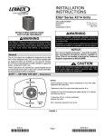
1
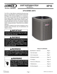
Service Literature
Corp. 0521−L9
Revised 09−2007
XC13
XC13 SERIES UNITS
The XC13 is a high efficiency residential split−system condensing unit, which features a scroll compressor and
R−410A refrigerant. XC13 units are available in sizes ranging from 1 1/2 through 5 tons. The series is designed for use
with an expansion valve or RFC (approved for use with
R−410A) in the indoor unit. This manual is divided into sections which discuss the major components, refrigerant system, charging procedure, maintenance and operation sequence.
Information contained in this manual is intended for use by
qualified service technicians only. All specifications are subject to change.
WARNING
Improper installation, adjustment, alteration, service
or maintenance can cause property damage, personal injury or loss of life. Installation and service must
be performed by a qualified installer or service
agency.
IMPORTANT
WARNING
Warranty will be voided if covered equipment is removed from original installation site. Warranty will
not cover damage or defect resulting from:
Flood, wind, lightning, or installation and operation
in a corrosive atmosphere (chlorine, fluorine, salt,
recycled waste water, urine, fertilizers, or other damaging chemicals).
Operating pressures of this R−410A unit are higher
than pressures in R−22 units. Always use service
equipment rated for R410A.
TABLE OF CONTENTS
General . . . . . . . . . . . . . . . . . . . . . . . . . . . . Page 1
Specifications / Electrical Data . . . . . . . . . Page 2
DANGER
I Application . . . . . . . . . . . . . . . . . . . . . . . . . Page 3
Shock Hazard
Remove all power at disconnect
before removing access panel.
Single phase XC13 units use singlepole contactors. Potential
exists for electrical shock resulting
in injury or death.
Line voltage exist at all components
(even when unit is not in operation).
II Unit Components . . . . . . . . . . . . . . . . . . Page 3
III Refrigeration System . . . . . . . . . . . . . . . Page 7
IV Charging . . . . . . . . . . . . . . . . . . . . . . . . . Page 8
V Service and Recovery . . . . . . . . . . . . . . Page 14
VI Maintenance . . . . . . . . . . . . . . . . . . . . . . Page 14
VII Wiring and Sequence of Operation . . Page 15
Page 1
©2005 Lennox Industries Inc.
SPECIFICATIONS
Model No. XC13−018
General
Data
Connections
(
(sweat)
t)
Refrigerant
Outdoor
Coil
XC13−024
XC13−030
XC13−036
XC13−042
XC13−048
Nominal Tonnage
1.5
2
2.5
3
3.5
4
Liquid line (o.d.) − in. (mm) 3/8 (9.5)
3/8 (9.5)
3/8 (9.5)
3/8 (9.5)
3/8 (9.5)
3/8 (9.5)
7/8 (22.2)
Suction line (o.d.) − in. (mm) 3/4 (19.1) 3/4 (19.1) 3/4 (19.1) 7/8 (22.2) 7/8 (22.2)
1 R−410A charge furnished 4 lbs. 10 oz. 5 lbs. 6 oz. 7 lbs. 2 oz. 7 lbs. 4 oz. 8 lbs. 10 oz. 9 lbs. 2 oz.
(2.1 kg)
(2.44 kg)
(3.23 kg)
(3.29 kg)
(3.91 kg)
(4.14 kg)
Net face area
sq.
q ft. (m2)
( )
Outer coil 13.22 (1.23) 15.11 (1.40) 13.22 (1.23) 18.67 (1.73) 16.33 (1.52) 16.33 (1.52)
Inner coil
−−−
−−−
12.65 (1.18)
−−−
15.76 (1.46) 15.76 (1.46)
Tube diameter − in. (mm)
5/16 (8)
5/16 (8)
5/16 (8)
5/16 (8)
5/16 (8)
5/16 (8)
No. of rows
1
1
2
1
2
2
Fins per inch (m) 22 (867)
22 (867)
22 (867)
22 (867)
22 (867)
22 (867)
Diameter − in. (mm) 18 (457)
18 (457)
18 (457)
22 (559)
22 (559)
22 (559)
Outdoor
F
Fan
3
3
3
4
4
No. of blades
3
Motor hp (W) 1/10 (75)
1/10 (75)
1/5 (149)
1/5 (149)
1/6 (124)
1/6 (124)
Cfm (L/s) 2360 (1115) 2330 (1100) 2320 (1095) 3440 (1625) 3060 (1445) 3060 (1445)
Rpm
1055
1050
1130
1055
845
845
Watts
150
140
165
220
215
215
Shipping Data − lbs. (kg) 1 pkg.
158 (72)
166 (75)
179 (81)
211 (96)
232 (105)
232 (105)
ELECTRICAL DATA
Line voltage data − 60hz − 1 phase
2 Maximum overcurrent protection (amps)
3 Minimum circuit ampacity
Rated load amps
Compressor
p
Locked rotor amps
Power factor
Full load amps
Outdoor Fan
M t
Motor
Locked Rotor Amps
208/230V
20
11.9
8.97
48
0.98
0.7
1.4
XC13−060
*−3 units
5
3/8 (9.5)
1−1/8 (28.6)
12 lbs. 6 oz.
(5.61 kg)
*10 lbs 0 oz
(4.5 kg)
24.50 (2.28)
*21 (1.95)
23.64 (2.19)
*20.25
(1.88)
5/16 (8)
2
22 (867)
22 (559)
4
1/4 (186)
3980 (1880)
836
305
285 (129)
*268 (122)
208/230V
30
17.5
13.46
58
0.98
0.7
1.4
208/230V
30
18.7
14.1
73
0.98
1.1
2
208/230V
35
21.9
16.67
79
0.99
1.1
2
208/230V
40
23.2
17.69
107
0.99
1.1
2.1
208/230V
50
28.3
21.79
117
0.99
1.1
2.1
208/230V
60
34.6
26.28
134
0.99
1.7
3.1
Furnished
OPTIONAL ACCESSORIES − must be ordered extra
Compressor Crankcase Heater
Compressor
p
Hard Start Kit
67K90
10J42
88M91
Compressor Low Ambient Cut−Off 45F08
Compressor Time−Off Control
47J27
3/8 in. tubing
93G35
Freezestat
1/2 in. tubing
39H29
5/8 in. tubing
50A93
Low Ambient Kit
34M72
Mounting Base
69J07
L15−41−20
L15−41−40
Refrigerant
L15−41−30
L15−41−50
Line Sets
L15−65−40
L15−65−30
L15−65−50
Field Fabricate
Time Delay Relay
58M81
NOTE − Extremes of operating range are plus 10% and minus 5% of line voltage.
1
Refrigerant charge sufficient for 15 ft. (4.6 m) length of refrigerant lines.
2
Refer to National or Canadian Electrical Code manual to determine wire, fuse and disconnect size requirements.
3
HACR type breaker or fuse.
Page 2
I − APPLICATION
Removing/Installing Louvered Panels
XC13 condensing units are available in 1 1/2, 2, 2 -1/2, 3,
3 -1/2, 4 and 5 ton capacities. All major components (indoor
blower and coil) must be matched according to Lennox recommendations for the compressor to be covered under warranty. Refer to the Engineering Handbook for approved system matchups.
II − UNIT COMPONENTS
Panel shown slightly rotated to allow top tab to exit (or enter) top
slot for removing (or installing) panel.
SCREW
HOLES
LIP
Unit components are illustrated in figure 1.
Detail
A
XC13 PARTS ARRANGEMENT
DUAL CAPACITOR
IMPORTANT! Do not allow panels to hang on unit by top tab. Tab
is for alignment and not designed to support weight of panel.
OUTDOOR FAN
Detail
B
COMPRESSOR
CONTACTOR
ROTATE IN THIS DIRECTION;
THEN DOWN TO REMOVE PANEL
FILTER DRIER
Detail C
HIGH PRESSURE
SWITCH
FIGURE 1
MAINTAIN MINIMUM PANEL ANGLE (AS CLOSE TO PARALLEL WITH THE UNIT
AS POSSIBLE) WHILE INSTALLING PANEL.
HOLD DOOR FIRMLY TO THE HINGED
ANGLE MAY BE TOO
SIDE TO MAINTAIN
EXTREME
FULLY−ENGAGED TABS
PREFERRED ANGLE
FOR INSTALLATION
CAUTION
To prevent personal injury, or damage to panels, unit
or structure, be sure to observe the following:
While installing or servicing this unit, carefully stow
all removed panels out of the way, so that the panels
will not cause injury to personnel, nor cause damage
to objects or structures nearby, nor will the panels be
subjected to damage (e.g., being bent or scratched).
While handling or stowing the panels, consider any
weather conditions, especially windy conditions, that
may cause panels to be blown around and battered.
Remove the louvered panels as follows:
1.Remove 2 screws, allowing the panel to swing open slightly (see figure 2).
Page 3
Detail D
FIGURE 2
2.Hold the panel firmly throughout this procedure. Rotate bottom corner of panel away from hinge corner post
until lower 3 tabs clear the slots (see figure 2, Detail B).
3.Move panel down until lip of upper tab clears the top slot
in corner post (see figure 2, Detail A).
Position and Install PanelPosition the panel almost parallel with the unit (figure 2, Detail D) with the screw side" as
close to the unit as possible. Then, in a continuous motion:
Slightly rotate and guide the lip of top tab inward (figure 2,
Details A and C); then upward into the top slot of the
hinge corner post.
Rotate panel to vertical to fully engage all tabs.
Holding the panel’s hinged side firmly in place, close the
right−hand side of the panel, aligning the screw holes.
When panel is correctly positioned and aligned, insert the
screws and tighten.
A − Control Box (Figure 3)
XC13 units are not equipped with a 24V transformer. All 24
VAC controls are powered by the indoor unit. Refer to wiring diagram.
Electrical openings are provided under the control box cover. Field thermostat wiring is made to color-coded pigtail
connections.
ELECTROSTATIC DISCHARGE (ESD)
Precautions and Procedures
CAUTION
1 − Compressor Contactor K1
The compressor is energized by a single−pole contactor located in the control box. See figure 3. K1 is energized by the
indoor thermostat terminal Y1 (24V) when thermostat demand is present.
2 − Dual Capacitor C12
The compressor and fan in XC13 series units use permanent split capacitor motors. The capacitor is located inside the unit control box (see figure 3). A single dual" capacitor (C12) is used for both the fan motor and the compressor (see unit wiring diagram). The fan side and the
compressor side of the capacitor have different MFD ratings. See side of capacitor for ratings.
3 − Timed Off Control TOC (option)
The time delay is electrically connected between thermostat
terminal Y and the compressor contactor. Between cycles,
the compressor contactor is delayed for 5 minutes ± 2 minutes but may last as long as 8 minutes. At the end of the
delay, the compressor is allowed to energize. When thermostat demand is satisfied, the time delay opens the circuit to
the compressor contactor coil and the compressor is de−energized.
B − Compressor
Electrostatic discharge can affect electronic components. Take precautions during unit installation
and service to protect the unit’s electronic controls.
Precautions will help to avoid control exposure to
electrostatic discharge by putting the unit, the control and the technician at the same electrostatic potential. Neutralize electrostatic charge by touching
hand and all tools on an unpainted unit surface before performing any service procedure.
CONTROL BOX
DUAL CAPACITOR
(C12)
The scroll compressor used in all XC13 model units, are designed for use with R410A refrigerant and operation at high
pressures. Compressors are shipped from the factory
charged with 3MA (32MMMA) P.O.E. oil.
See ELECTRICAL DATA table at the front of this manual or
compressor nameplate for compressor specifications.
The scroll compressor design is simple, efficient and requires
few moving parts. A cutaway diagram of the scroll compressor
is shown in figure 4. The scrolls are located in the top of the
compressor can and the motor is located just below. The oil level is immediately below the motor.
SCROLL COMPRESSOR
DISCHARGE
COMPRESSOR
CONTACTOR
(K1)
SUCTION
TIMED OFF
CONTROL.
(OPTION)
GROUNDING
LUG
FIGURE 3
FIGURE 4
Page 4
The scroll is a simple compression concept centered around
the unique spiral shape of the scroll and its inherent properties.
Figure 5 shows the basic scroll form. Two identical scrolls are
mated together forming concentric spiral shapes (figure 6). One
scroll remains stationary, while the other is allowed to "orbit" (figure 7). Note that the orbiting scroll does not rotate or turn but
merely orbits the stationary scroll.
NOTE − During operation, the head of a scroll compressor may
be hot since it is in constant contact with discharge gas.
CROSS−SECTION OF SCROLLS
DISCHARGE
STATIONARY SCROLL
DISCHARGE
PRESSURE
SUCTION
SCROLL FORM
TIPS SEALED BY
DISCHARGE PRESSURE
ORBITING SCROLL
FIGURE 6
FIGURE 5
SUCTION
SUCTION
1
INTERMEDIATE PRESSURE
GAS
2
ORBITING SCROLL
CRESCENT
SHAPED
GAS POCKET
STATIONARY SCROLL
SUCTION
POCKET
FLANKS SEALED
SUCTION
BY CENTRIFUGAL
FORCE
SUCTION
MOVEMENT OF ORBIT
3
HIGH PRESSURE GAS
FIGURE 7
Page 5
4
DISCHARGE
POCKET
The counterclockwise orbiting scroll draws gas into the outer
crescent shaped gas pocket created by the two scrolls (figure 7
− 1). The centrifugal action of the orbiting scroll seals off the
flanks of the scrolls (figure 7 − 2). As the orbiting motion continues, the gas is forced toward the center of the scroll and the gas
pocket becomes compressed (figure 7 − 3). When the compressed gas reaches the center, it is discharged vertically into a
chamber and discharge port in the top of the compressor (figure
6). The discharge pressure forcing down on the top scroll helps
seal off the upper and lower edges (tips) of the scrolls (figure 6).
During a single orbit, several pockets of gas are compressed
simultaneously providing smooth continuous compression.
The scroll compressor is tolerant to the effects of liquid return. If
liquid enters the scrolls, the orbiting scroll is allowed to separate
from the stationary scroll. The liquid is worked toward the center
of the scroll and is discharged. If the compressor is replaced,
conventional Lennox cleanup practices must be used.
Due to its efficiency, the scroll compressor is capable of drawing a much deeper vacuum than reciprocating compressors.
Deep vacuum operation can cause internal fusite arcing
resulting in damaged internal parts and will result in compressor failure. Never use a scroll compressor for evacuating or pumping−down" the system. This type of damage can be detected and will result in denial of warranty
claims.
The scroll compressor is quieter than a reciprocating compressor, however, the two compressors have much different
sound characteristics. The sounds made by a scroll compressor do not affect system reliability, performance, or indicate
damage.
Access to the condenser fan motor on all units is gained
by removing the four screws securing the fan assembly.
See figure 8. The grill fan assembly can be removed from
the cabinet as one piece. See figure 9. The condenser fan
motor is removed from the fan guard by removing the four
nuts found on top of the grill. See figure 9 if condenser fan
motor replacement is necessary.
DANGER
Make sure all power is disconnected before
beginning electrical service procedures.
Remove
screws
Remove
screws
FIGURE 8
C − Drier
A filter drier designed for all XC13 model units must be
installed in the liquid line. The factory installed drier is designed to remove moisture, which can lead to compressor
failure. Any time unit is exposed to open air due to service, drier must be replaced. All replacement driers
must be approved for R410A refrigerant.
ALIGN FAN HUB FLUSH WITH END OF SHAFT
FIGURE 9
D − Condenser Fan Motor
E − Loss of Charge Switch
All units use single−phase PSC fan motors which require a run
capacitor. In all units, the condenser fan is controlled by
the compressor contactor.
The loss of charge switch is NC, auto re−set and located on
the discharge line of the compressor. The switch opens
when discharge line temperatures exceeds the factory setting of 220° + 5° F and shuts down the compressor.
ELECTRICAL DATA tables in this manual show specifications for condenser fans used in XC13’s.
F − High Pressure Switch
XC13 units are equipped with a high pressure switch that is
located in the liquid line of the compressor. The switch
(SPST, manual reset, normally closed) removes power from
the compressor contactor control circuit when discharge
pressure rises above factory setting at 590 + 10 psi.
Page 6
III − REFRIGERANT SYSTEM
A − Plumbing
To Close Service Valve:
Field refrigerant piping consists of liquid and suction lines
from the condensing unit (sweat connections) to the indoor
evaporator coil (sweat connections). Use Lennox L15
(sweat) series line sets as shown in table 1.
TABLE 1
2 − Using the adjustable wrench to keep the valve stationary, use a service wrench with a hex−head extension to
turn the stem clockwise to seat the valve. Tighten the
stem firmly.
1 − Remove the stem cap with an adjustable wrench.
Unit
Liquid
Line
Suction
Line
L15 Line
Sets
018, −024,
−030,
3/8 in.
(10 mm)
3/4 in.
(19 mm)
L15−41
20 ft. − 50 ft.
(6 m − 15 m)
−036, −042,
−048
3/8 in.
(10 mm)
7/8 in.
(22 mm)
L15−65
30 ft. − 50 ft.
(9 m − 15 m)
−060
3/8 in.
(10 mm)
1−1/8 in.
(29 mm)
Field
Fabricated
NOTE − Use a 3/16" hex head extension for 3/8" line
sizes or a 5/16" extension for large line sizes.
3 − Replace the stem cap. Tighten finger tight, then tighten an
additional 1/6 turn.
IMPORTANT
NOTE − Stem cap must be replaced to help prevent
valve leakage.
Service Valve
(Valve Closed)
stem cap
service
port
insert hex
wrench here
to outdoor coil
service
port cap
Only use Allen wrenches of sufficient hardness
(50Rc − Rockwell Harness Scale min). Fully insert the wrench into the valve stem recess.
Service valve stems are factory torqued (from 9
ft lbs for small valves, to 25 ft lbs for large
valves) to prevent refrigerant loss during shipping and handling. Using an Allen wrench rated
at less than 50Rc risks rounding or breaking off
the wrench, or stripping the valve stem recess.
to indoor coil
Schrader valve open
to line set when valve is
closed (front seated)
(valve front seated)
The liquid line and vapor line service valves (figures 10 and
11) and gauge ports are accessible from the outside of the
unit. Use the service ports for leak testing, evacuating,
charging and checking charge.
Each valve is equipped with a service port which has a factory−installed Schrader valve. A service port cap protects the
Schrader valve from contamination and serves as the primary leak seal. Service valves are not rebuildable. If a valve
has failed, you must replace it.
To Access Schrader Port:
1 − Remove service port cap with an adjustable wrench.
2 − Connect gauge to the service port.
3 − When testing is complete, replace service port cap. Tighten finger tight, then an additional 1/6 turn.
insert hex
wrench here
Service Valve
(Valve Open)
stem cap
service
port
to outdoor coil
service port
cap
to indoor coil
Schrader
valve
FIGURE 10
To Open Service Valve:
Vapor Line Ball Valve – 5 Ton Units Only
1 − Remove the stem cap with an adjustable wrench.
2 − Using the adjustable wrench to keep the valve stationary, use a service wrench with a hex−head extension to
back the stem out counterclockwise as far as it will go.
NOTE − Use a 3/16" hex head extension for 3/8" line
sizes or a 5/16" extension for large line sizes.
3 − Replace the stem cap. Tighten finger tight, then tighten
an additional 1/6 turn.
Vapor line service valves function the same way as the other
valves, the difference is in the construction. A ball valve is
illustrated in figure 11.
Page 7
The ball valve is equipped with a service port with a factory−
installed Schrader valve. A service port cap protects the
Schrader valve from contamination and assures a leak−free
seal.
Ball Valve (Valve Open)
WARNING
Use Adjustable Wrench
To open: rotate Stem Clockwise 90°.
To close: rotate Stem Counter-clockwise 90°.
Danger of explosion!
When using a high pressure gas such
as dry nitrogen to pressurize a refrigerant or air conditioning system, use a
regulator that can control the pressure
down to 1 or 2 psig (6.9 to 13.8 kPa).
stem cap
to outdoor coil
stem
ball
(shown open)
Using an Electronic Leak Detector
to indoor coil
service port
cap
service port
Schrader valve
FIGURE 11
IV − CHARGING
WARNING
R−410A refrigerant can be harmful if it is inhaled.
R−410A refrigerant must be used and recovered responsibly.
Failure to follow this warning may result in personal
injury or death.
A − Leak Testing
After the line set has been connected to the indoor and outdoor units, check the line set connections and indoor unit
for leaks.
IMPORTANT
The Clean Air Act of 1990 bans the intentional venting
of (CFC’s and HFC’s) as of July 1, 1992. Approved
methods of recovery, recycling or reclaiming must be
followed. Fines and/or incarceration my be levied for
noncompliance.
WARNING
Fire, Explosion and Personal Safety
Hazard.
Failure to follow this warning could result in damage, personal injury or death.
Never use oxygen to pressurize or
purge refrigeration lines. Oxygen, when
exposed to a spark or open flame, can
cause damage by fire and / or an explosion, that can result in personal injury or
death.
1 − Connect a cylinder of R−410A to the center port of the
manifold gauge set. Connect manifold gauge to service
valve port.
2 − With both manifold valves closed, open the valve on the
R−410A cylinder.
3 − Open the high pressure side of the manifold to allow the
R−410A into the line set and indoor unit. Weigh in a trace
amount of R−410A. [A trace amount is a maximum of 2
ounces (57 g) or 3 pounds (31 kPa) pressure.] Close the
valve on the R−410A cylinder and the valve on the high
pressure side of the manifold gauge set. Disconnect the
R−410A cylinder.
4 − Connect a cylinder of nitrogen with a pressure regulating valve to the center port of the manifold gauge set.
5 − Connect the manifold gauge set high pressure hose to
the vapor valve service port. (Normally, the high pressure hose is connected to the liquid line port; however,
connecting it to the vapor port better protects the manifold gauge set from high pressure damage.)
6 − Adjust the nitrogen pressure to 150 psig (1034 kPa).
Open the valve on the high side of the manifold gauge
set which will pressurize line set and indoor unit.
7 − After a few minutes, open a refrigerant port to ensure
the refrigerant you added is adequate to be detected.
(Amounts of refrigerant will vary with line lengths.)
Check all joints for leaks. Purge nitrogen and R−410A
mixture. Correct any leaks and recheck.
B − Evacuating
Evacuating the system of noncondensables is critical for
proper operation of the unit. Noncondensables are defined
as any gas that will not condense under temperatures and
pressures present during operation of an air conditioning
system. Noncondensables and water vapor combine with
refrigerant to produce substances that corrode copper piping and compressor parts.
NOTE − This evacuation process is adequate for a new
installation with clean and dry lines. If excessive moisture is present, the evacuation process may be required
more than once.
IMPORTANT
Use a thermocouple or thermistor electronic vacuum
gauge that is calibrated in microns. Use an instrument
that reads from 50 microns to at least 10,000 microns.
Page 8
1 − Connect manifold gauge set to the service valve ports :
low pressure gauge to vapor line service valve
high pressure gauge to liquid line service valve
2 − Connect micron gauge.
3 − Connect the vacuum pump (with vacuum gauge) to the
center port of the manifold gauge set.
4 − Open both manifold valves and start the vacuum
pump.
5 − Evacuate the line set and indoor unit to an absolute
pressure of 23,000 microns (29.01 inches of mercury).
During the early stages of evacuation, it is desirable to
close the manifold gauge valve at least once to determine if there is a rapid rise in absolute pressure. A rapid rise in pressure indicates a relatively large leak. If this
occurs, repeat the leak testing procedure.
NOTE − The term absolute pressure means the total
actual pressure within a given volume or system, above
the absolute zero of pressure. Absolute pressure in a
vacuum is equal to atmospheric pressure minus vacuum pressure.
6 − When the absolute pressure reaches 23,000 microns
(29.01 inches of mercury), close the manifold gauge
valves, turn off the vacuum pump and disconnect the
manifold gauge center port hose from vacuum pump.
Attach the manifold center port hose to a nitrogen cylinder with pressure regulator set to 150 psig (1034 kPa)
and purge the air from the hose with nitrogen. Open the
manifold gauge valves to break the vacuum in the line
set and indoor unit. Close the manifold gauge valves.
CAUTION
Danger of Equipment Damage.
Avoid deep vacuum operation. Do not use compressors to evacuate a system.
Extremely low vacuums can cause internal arcing and
compressor failure.
Damage caused by deep vacuum operation will void
warranty.
7 − Shut off the nitrogen cylinder and remove the manifold
gauge hose from the cylinder. Open the manifold gauge
valves to release the nitrogen from the line set and indoor unit.
8 − Reconnect the manifold gauge to the vacuum pump,
turn the pump on, and continue to evacuate the line set
and indoor unit until the absolute pressure does not rise
above 500 microns (29.9 inches of mercury) within a
20−minute period after shutting off the vacuum pump
and closing the manifold gauge valves.
Page 9
9 − When the absolute pressure requirement above has
been met, disconnect the manifold hose from the vacuum pump and connect it to an upright cylinder of R−410A
refrigerant. Open the manifold gauge valves to break the
vacuum from 1 to 2 psig positive pressure in the line set
and indoor unit. Close manifold gauge valves and shut
off the R−410A cylinder and remove the manifold gauge
set.
C − Charging
NOTES −
R−410A refrigerant cylinders are rose−colored. Refrigerant should be added through the vapor valve
in the liquid state.
Certain R−410A cylinders are identified as being
equipped with a dip tube. These allow liquid refrigerant to be drawn from the bottom of the cylinder
without inverting the cylinder. DO NOT turn this type
cylinder upside−down to draw refrigerant.
IMPORTANT
Use table 7 to perform maintenance checks. Table 7 is
not a procedure for charging the system. Minor variations in these pressures may be due to differences in
installations. Significant deviations could mean that
the system is not properly charged or that a problem
exists with some component in the system.
This system is charged with R−410A refrigerant which operates at much higher pressures than R−22. The installed liquid line filter drier is approved for use with R−410A. Do not
replace it with components designed for use with R−22. This
unit is NOT approved for use with coils which use capillary
tubes as a refrigerant metering device.
Factory Charge
Units are factory charged with the amount of R−410A refrigerant indicated on the unit rating plate. This charge is based
on a matching indoor coil and outdoor coil with 15 ft. (4.6 m)
line set. For varying lengths of line set, refer to table 2 for refrigerant charge adjustment.
TABLE 2
Refrigerant Charge per Line Set Lengths
Liquid Line
Set Diameter
Oz. per 5 ft. (g per 1.5 m) adjust
from 15 ft. (4.6 m) line set*
3/8 in. (9.5 mm)
3 ounce per 5 ft. (85 g per 1.5 m)
*If line length is greater than 15 ft. (4.6 m), add this amount.
If line length is less than 15 ft. (4.6 m), subtract this
amount.
IMPORTANT
Mineral oils are not compatible with R−410A. If oil
must be added, it must be a polyol ester oil.
The compressor is charged with sufficient polyol ester oil for approved line set lengths.
Units Delivered Void of Charge
If the system is void of refrigerant, clean the system using
the procedure described below.
1 − Use dry nitrogen to pressurize the system and check for
leaks. Repair leaks, if possible.
2 − Evacuate the system to remove as much of the moisture
as possible. Use dry nitrogen to pressurize the system
and check for leaks. Repair leaks, if possible.
3 − Use dry nitrogen to break the vacuum and install the provided filter drier in the system.
4 − Evacuate the system again. Then, weigh the appropriate
amount of R−410A refrigerant (listed on unit nameplate)
into the system.
5 − Monitor the system to determine the amount of moisture
remaining in the oil. Use test kit 10N46 to verify that the
moisture content is within the kit’s dry color range. It
may be necessary to replace the filter drier several
times to achieve the required dryness level.
If system dryness is not verified, the compressor
will fail in the future.
Measure the liquid line temperature and the outdoor ambient temperature as outlined below:
1 − Connect the manifold gauge set to the service valves:
low pressure gauge to vapor valve service port
high pressure gauge to liquid valve service port
2 − Close manifold gauge set valves. Connect the center
manifold hose to an upright cylinder of R−410A .
3 − Set the room thermostat to call for heat. This will create
the necessary load for properly charging the system in
the cooling cycle.
4 − Record outdoor ambient temperature using a digital thermometer.
5 − When the heating demand has been satisfied, switch the
thermostat to cooling mode with a set point of 68F
(20C). When pressures have stabilized, use a digital
thermometer to record the liquid line temperature.
6 − The outdoor temperature will determine which charging
method to use. Proceed with the appropriate charging
procedure.
Charge Using Weigh-in Method, Fixed Orifice or
TXV SystemsOutdoor Temp. < 65ºF (18ºC)
If the system is void of refrigerant, or if the outdoor ambient
temperature is cool, first, locate and repair any leaks and
then weigh in the refrigerant charge into the unit.
Checking Charge
1 − Recover the refrigerant from the unit.
The outdoor unit should be charged during warm weather.
However, applications arise in which charging must occur in
the colder months. The method of charging is determined by
the unit’s refrigerant metering device and the outdoor
ambient temperature.
2 − Conduct leak check; evacuate as previously outlined.
3 − Weigh in the unit nameplate charge. If weighing facilities
are not available or if charging the unit during warm
weather, use one of the following procedures.
Page 10
TABLE 3
Charge Using Subcooling Method, Fixed Orifice
SystemsOutdoor Temp. > 65ºF (18ºC)
R−410A Temperature (°F) − Pressure (Psig)
If charging a fixed orifice system when the outdoor ambient
is 65F (18C) or above, use the subcooling method to
charge the unit.
NOTE − To determine saturation temperature/pressure, use
the R−410A temperature/pressure chart (table 3).
1 − With the manifold gauge hose still on the liquid service
port and the unit operating stably, use a digital thermometer to record the liquid line temperature.
2 − At the same time, record the liquid line pressure reading.
3 − Determine the saturation temperature for the liquid line
pressure reading. See table 3.
4 − Subtract the liquid line temperature from the saturation
temperature (according to the chart) to determine subcooling.
5 − Compare the subcooling value with those in table 4. If
subcooling is greater than shown, recover some refrigerant. If subcooling is less than shown, add some refrigerant.
°F
Psig
°F
Psig
°F
Psig
°F
Psig
32
34
36
38
40
42
44
46
48
50
52
54
56
58
60
62
100.8
105.0
109.2
113.6
118.0
122.6
127.3
132.2
137.1
142.2
147.4
152.8
158.2
163.9
169.6
195.5
64
66
68
70
72
74
76
78
80
82
84
86
88
90
92
94
181.6
187.7
194.1
200.6
207.2
214.0
220.9
228.0
235.3
242.7
250.3
258.0
266.0
274.1
282.3
290.8
96
98
100
102
104
106
108
110
112
114
116
118
120
122
124
126
299.4
308.2
317.2
326.4
335.7
345.3
355.0
365.0
375.1
385.4
396.0
406.7
417.7
428.8
440.2
451.8
126
128
130
132
134
136
138
140
142
144
146
148
150
152
154
156
451.8
463.5
475.6
487.8
500.2
512.9
525.8
539.0
552.3
565.9
579.8
593.8
608.1
622.7
637.5
652.4
TABLE 4
XC13 Subcooling Values − Fixed Orifice Systems
Model
Outdoor
Temperature
°F (°C)
65 (18)
70 (18)
75 (24)
80 (24)
85 (29)
90 (35)
95 (35)
100 (41)
105 (41)
110 (41)
115 (45)
−018
=
−024
−030
Saturation Temperature F (C)
Liquid Line Temperature F (C)
Subcooling Value F (C)
−036
−042
−048
−060
8 (4.4)
14 (7.7)
10 (5.5)
10 (5.5)
13 (7.2)
15 (8.3)
11 (6)
4 (2.2)
13 (7.2)
9 (5)
8 (4.4)
12 (6.7)
14 (7.7)
10 (5.5)
3 (1.7)
12 (6.7)
8 (4.4)
7 (4)
11 (6)
13 (7.2)
10 (5.5)
2 (1)
11 (6)
7 (4)
7 (4)
11 (6)
12 (6.7)
10 (5.5)
2 (1)
11 (6)
6 (3.3)
6 (3.3)
10 (5.5)
11 (6)
9 (5)
2 (1)
9 (5)
5 (2.7)
5 (2.7)
9 (5)
10 (5.5)
9 (5)
2 (1)
9 (5)
4 (2.2)
4 (2.2)
8 (4.4)
9 (5)
8 (4.4)
1 (0.5)
7 (4)
4 (2.2)
4 (2.2)
7 (4)
9 (5)
8 (4.4)
1 (0.5)
6 (3.3)
3 (1.7)
3 (1.7)
7 (4)
8 (4.4)
7 (4)
1 (0.5)
6 (3.3)
2 (1)
2 (1)
6 (3.3)
7 (4)
7 (4)
1 (0.5)
5 (2.7)
2 (1)
2 (1)
5 (2.7)
6 (3.3)
6 (3.3)
Page 11
TABLE 5
Charge using Subcooling Method (TXV Systems) − Outdoor Temp. >40ºF (4ºC)
This charging procedure should not be used if ambient temperatures are below 40ºF. For best results, indoor temperature should be 70ºF (21ºC) to 80ºF (26ºC).
1.Restrict the airflow (see figure 12) through the outdoor coil
to achieve pressures from 325−375 psig (2240−2585
kPa). These higher pressures are necessary for checking the charge. Block equal sections of air intake panels
and move coverings sideways until the liquid pressure
is in the above noted ranges.
Blocking Outdoor Coil
*Outdoor coil should be blocked one
side at a time with cardboard or plastic
sheet until proper testing pressures are
reached.
cardboard or plastic sheet
*Four−sided unit shown.
FIGURE 12
2.With the manifold gauge hose installed on the liquid service port and the unit operating stably, use a digital thermometer to record the liquid line temperature.
3.At the same time, record the liquid line pressure reading.
Subcooling Values TXV Systems
XC13
Model
Temp.
°F (°C)
018
024
030
036
042
048
060
060−3
3
(1.7)
6
(3.3)
11
(6)
7
(4)
7
(4)
10
(5.5)
10
(5.5)
7
(4)
Charge Using the Approach Method,
TXV SystemsOutdoor Temperature > 65ºF (18ºC)
The following procedure is intended as a general guide and is
for use on expansion valve systems only. For best results,
outdoor temperature should be 70°F (21°C) to 80°F (26°C).
Monitor system pressures while charging.
1 − Record outdoor ambient temperature using a digital thermometer.
2 − Attach high pressure gauge set and operate unit for several minutes to allow system pressures to stabilize.
3 − Use the same digital thermometer you used to check the
outdoor ambient temperature to check the liquid line
temperature.
4 − The difference between the ambient and liquid temperatures should match values given in table 6. If the values
don’t agree with the those in table 6, add refrigerant to
lower the approach temperature, or recover refrigerant
from the system to increase the approach temperature.
4.Use a temperature/pressure chart in table 3 for R−410A refrigerant to determine the saturation temperature for the
liquid line pressure reading.
5.Subtract the refrigerant saturation temperature from the
liquid line temperature to determine subcooling.
Compare to table 5.
=
TABLE 6
Approach Values
XC13
Model
Temp.
°F (°C)
Saturation Temperature F (C)
Liquid Line Temperature F (C)
Subcooling Value F (C)
=
Page 12
018
024
030
036
042
048
060
060−3
12
(6.7)
12
(6.7)
7
(4)
10
(5.5)
7
(4)
7
(4)
9
(5)
9
(5)
Liquid Line Temperature F (C)
Outdoor Ambient Temperature F (C)
Approach Value F (C)
TABLE 7
XC13 Normal Operating Pressures (Liquid +10 & Suction +5 psig)
Model
−018
−024
−030
−036
−042
−048
−060
−060−3
The values below are typical pressures; indoor evaporator match up, indoor air quantity, and evaporator load will cause the
pressures to vary.
Liquid Line Pressure / Vapor Line Pressure
*°F (°C)
Fixed Orifice
65 (18)
238 / 130
249 / 126
239 / 124
251 / 129
240 / 120
249 / 123
243 / 117
255 / 126
70 (21)
253 / 130
269 / 130
257 / 127
271 / 132
260 / 124
267 / 126
264 / 120
274 / 128
75 (24)
273 / 134
288 / 133
277 / 129
291 / 135
280 / 128
286 / 129
285 / 123
294 / 131
80 (26)
295 / 138
310 / 136
298 / 132
312 / 137
301 / 131
306 / 131
306 / 126
317 / 134
85 (29)
316 / 141
331 / 138
320 / 135
334 / 139
323 / 133
328 / 133
329 / 129
339 / 136
90 (32)
339 / 144
352 / 141
342 / 138
358 / 142
344 / 135
349 / 135
352 / 131
362 / 138
95 (35)
363 / 147
379 / 143
365 / 140
383 / 143
368 / 137
372 / 137
376 / 134
386 / 140
100 (38)
386 / 149
400 / 144
390 / 142
408 / 145
390 / 139
396 / 139
402 / 136
413 / 142
105 (41)
411 / 151
425 / 147
414 / 143
435 / 147
417 / 141
419 / 141
427 / 137
435 / 144
110 (43)
437 / 153
453 / 148
440 / 145
460 / 148
440 / 142
446 / 143
456 / 139
462 / 146
115 (46)
467 / 155
481 / 150
468 / 147
490 / 150
468 / 144
475 / 145
485 / 141
490 / 148
65 (18)
237 / 135
244 / 136
243 / 131
238 / 133
231 / 129
247 / 130
250 / 125
242 / 130
70 (21)
255 / 136
263 / 137
262 / 131
256 / 134
250 / 130
264 / 132
270 / 126
266 / 131
75 (24)
275 / 137
283 / 138
281 / 132
278 / 135
269 / 131
281 / 134
291 / 127
286 / 132
80 (26)
295 / 138
306 / 140
303 / 133
300 / 136
291 / 133
307 / 136
312 / 129
309 / 133
85 (29)
317 / 139
326 / 141
325 / 134
324 / 137
314 / 134
325 / 137
334 / 130
332 / 134
90 (32)
339 / 140
351 / 141
348 / 135
348 / 138
336 / 135
353 / 138
358 / 132
357 / 135
95 (35)
363 / 142
376 / 142
372 / 136
374 / 139
362 / 135
386 / 139
383 / 133
381 / 136
100 (38)
387 / 143
400 / 143
397 / 137
400 / 140
383 / 137
403 / 140
408 / 134
407 / 137
105 (41)
413 / 144
428 / 144
422 / 139
429 / 142
409 / 139
428 / 141
434 / 136
433 / 138
110 (43)
440 / 145
456 / 145
449 / 140
458 / 143
435 / 140
457 / 142
461 / 137
459 / 140
115 (46)
471 / 147
486 / 146
478 / 141
500 / 144
463 / 142
485 / 144
489 / 139
488 / 141
Expansion Valve
*Temperature of the air entering the outside coil.
Page 13
V − SERVICE AND RECOVERY
VI − MAINTENANCE
WARNING
WARNING
Polyol ester (POE) oils used with R−410A refrigerant
absorb moisture very quickly. It is very important
that the refrigerant system be kept closed as much
as possible. DO NOT remove line set caps or service
valve stub caps until you are ready to make connections.
IMPORTANT
USE RECOVERY MACHINE RATED FOR R−410A
REFRIGERANT.
If the XC13 system must be opened for any kind of service,
such as compressor or drier replacement, you must take extra precautions to prevent moisture from entering the system. The following steps will help to minimize the amount of
moisture that enters the system during recovery of R−410A.
1 − Use a regulator−equipped nitrogen cylinder to break the
system vacuum. Do not exceed 5 psi. The dry nitrogen
will fill the system, purging any moisture.
2 − Remove the faulty component and quickly seal the system (using tape or some other means) to prevent additional moisture from entering the system.
3 − Do not remove the tape until you are ready to install new
component. Quickly install the replacement component.
4 − Evacuate the system to remove any moisture and other
non−condensables.
Any time the XC13 sealed system is opened, the drier
must be replaced and the system must be evacuated.
Any moisture not absorbed by the polyol ester oil can be removed by evacuation. Moisture that has been absorbed by
the compressor oil can be removed by replacing the drier.
IMPORTANT
Evacuation of system only will not remove moisture
from oil. Drier must be replaced to eliminate moisture from POE oil.
Electric shock hazard. Can cause injury or death. Before attempting to perform any service or maintenance, turn
the electrical power to unit OFF at disconnect switch(es). Unit may have
multiple power supplies.
At the beginning of each cooling season, the system should
be serviced. In addition, the system should be cleaned as
follows:
A − Outdoor Unit
1 − Clean and inspect the outdoor coil. The coil may be
flushed with a water hose. Ensure the power is turned
off before you clean the coil.
2 − Condenser fan motor is prelubricated and sealed. No
further lubrication is needed.
3 − Visually inspect connecting lines and coils for evidence
of oil leaks.
4 − Check wiring for loose connections.
5 − Check for correct voltage at unit (unit operating).
6 − Check amp−draw condenser fan motor.
Unit nameplate _________ Actual ____________ .
NOTE − If owner complains of insufficient cooling, the unit
should be gauged and refrigerant charge checked. Refer to
section on refrigerant charging in this instruction.
B − Indoor Coil
1 − Clean coil, if necessary.
2 − Check connecting lines and coils for evidence of oil
leaks.
3 − Check the condensate line and clean it if necessary.
C − Indoor Unit
1 − Clean or change filters.
2 − Adjust blower speed for cooling. Measure the pressure
drop over the coil to determine the correct blower CFM.
Refer to the unit information service manual for pressure
drop tables and procedure.
3 − Belt Drive Blowers − Check belt for wear and proper tension.
4 − Check all wiring for loose connections
5 − Check for correct voltage at unit (blower operating).
6 − Check amp−draw on blower motor
Unit nameplate_________ Actual ____________.
Page 14
VII − WIRING DIAGRAMS AND SEQUENCE OF OPERATION
XC13
NOTE− The thermostat used may be electromechanical or electronic.
NOTE− Transformer in indoor unit supplies power (24 VAC) to the thermostat and outdoor unit controls.
COOLING:
1− Cooling demand initiates at Y1 in the thermostat.
5 − − 24VAC from indoor unit (Y1) energizes the TOC timed off control (if used) , which energizes contactor K1.
6 − − K1-1 N.O. closes, energizing compressor (B1) and outdoor fan motor (B4).
4 − Compressor (B1) and outdoor fan motor (B4) begin immediate operation..
END OF COOLING DEMAND:
5− Cooling demand is satisfied. Terminal Y1 is de-energized.
6− Compressor contactor K1 is de-energized.
7− K1-1 opens and compressor (B1) and outdoor fan motor (B4) are de-energized and stop immediately.
Page 15