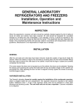
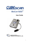
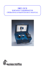
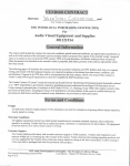
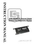
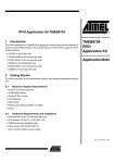
1
Small engine EFI conversion kits -Ninja250- user manual-v3_4_4.doc SE-EFI Small Engine Electronic Fuel Injection Ninja 250r Conversion Kit ECOTRONS User Manual V3.4.4 Confidential Page 1 4/15/2013 Small engine EFI conversion kits -Ninja250- user manual-v3_4_4.doc COPY RIGHTS ECOTRONS ALL RIGHTS RESERVED Note: This manual is based on a conversion of 1998 Ninja 250r model. Not all modifications and installations are applicable to all Ninja 250r model years; most modifications are applicable to 1994~2007 (pre-gen) and 2008-now (new-gen) Ninja 250r models (harnesses are a little different for pregen and new-gen. It can also apply to 1988 to 1993 models, but the harness again is different If your bike looks different than any of the pictures included in this manual, please contact us for exact installations of the whole kit. Confidential Page 2 4/15/2013 Small engine EFI conversion kits -Ninja250- user manual-v3_4_4.doc Table of Contents Introduction ........................................................................................................... 5 Installation Procedures ......................................................................................... 9 Section 1: .............................................................................................................. 9 1.Replace the dual-carburetor with the dual-throttle-body assembly .................9 2.Install the dual-throttle-body....................................................................... 10 3.Fuel tank petcock replacement ..............................................................................14 4.Install the fuel pump assembly................................................................... 15 5.Install the engine temperature sensor. ....................................................... 21 6.Install the intake air temperature sensor. ................................................... 21 Section 2: Install the ECU harness ..................................................................... 22 1. Harness picture:........................................................................................ 23 2. Label descriptions ..................................................................................... 26 3. O2 sensors ............................................................................................... 28 Section 3: Adjust two cylinders balance and idle RPM if need ............................ 31 1. How to adjust the idle air screw ................................................................ 31 2. Which factor can you reference when you adjust the balance ................. 32 Initial test: ............................................................................................................ 41 My engine does not start, why? .......................................................................... 42 Diagnosis: ........................................................................................................... 44 Supported DTC list (TBD) Diagnosis of your serial communications: ................. 46 How to use ProCAL to log data: .......................................................................... 47 How does the performance switch work? ........................................................... 47 Appendix A: Fuel supply system schematics: ..................................................... 48 Appendix B: Wiring harness diagram .................................................................. 50 Confidential Page 3 4/15/2013 Small engine EFI conversion kits -Ninja250- user manual-v3_4_4.doc SE-EFI Kit Confidential Page 4 4/15/2013 Small engine EFI conversion kits -Ninja250- user manual-v3_4_4.doc Introduction Kawasaki Ninja 250cc EFI PNP kit is a Plug-aNd-Play (PNP) EFI conversion kit to convert the Ninja 250 twin-cylinder carbureted engine to the fuel injected engine. This kit is designed to replace the twin 30mm carburetor with the twin the 28mm throttle body, and with some other minimal modifications, it can make the engine fuel injected at the low cost. This twin throttle body mimics the OEM's twin throttle body (2x28mm, European models), and it can be dropped into the place of the twin carburetor and make the EFI kit a Plug-aNd-Play (PNP) kit for Kawasaki Ninja 250cc engines. Note: the correct and complete installations are vital to make the kit running with the engine, even though it's designed for PNP. After-all there are a lot of components to be removed, replaced, and installed, and modified. The total conversion need quiet amount of efforts. Contact us if you are not sure whether you can do it yourself. This EFI kit has below features: • Electronic fuel injection (EFI) • ECU controlled ignition system (via CDI, optional, not included) • Plug-and-Play (PNP) with 2x O2 sensors • Dual fuel maps selectable by a manual switch (Performance Switch: ECO vs. RICH Mode) • High fuel efficiency and low carbon emissions • Decel-fuel-cut-off • On-board self-diagnosis with a MIL lamp • Fully tunable with a laptop tuning software (free). No need to add any other piggyback device • On-the-fly calibration Parts: 1.ECU (aluminum housing, full water proof, and EMI* proof) 2. Harness (including the connectors, waterproof) 3. Throttle Body • twin 28mm Throttle body (including TPS sensor) • 2x Fuel injector (128g/min) 4. Fuel pump assembly • Fuel pump (25L/h) • Fuel pressure regulator (3bar) • Fuel filter • Fuel hoses and clamps 5. MAP sensor (1.05bar) 6. Engine temperature sensor 7. Intake air temperature sensor 9. 2x Oxygen sensor and bungs (INCLUDED) 10. Serial communication cable (to a computer) Confidential Page 5 4/15/2013 Small engine EFI conversion kits -Ninja250- user manual-v3_4_4.doc 11. USB adaptor - included 12. CD - free tuning software (also downloadable) 13. Easy to upgrade to a turbo version (2.5bar MAP sensor, and 2x 128g injectors *EMI: Electro-Magnetic Interference. This kit does NOT require tuning for stock engines. With dual O2 sensors, the ECU can do full self-tuning for 2 cylinders individually. Yet it is fully tunable with a laptop software (ProCAL, free, downloadable), for performance. You may need some minor tuning, if you have significantly changed the engine, like high cams, or customer exhaust manifolds. Still, many users have run the kit with some aftermarket exhaust and air filters without having to re-tune it. This kit needs a 12V battery and charging system. Though the EFI is meant to reduce the emissions than a carb system, this kit is not certified for any emission regulations. It is the user's responsibility to find out whether it's legal to use it. MAP sensor Temperature sensors Fuel pump assembly Confidential Page 6 4/15/2013 Small engine EFI conversion kits -Ninja250- user manual-v3_4_4.doc Throttles with adaptor hoses to be PNP: Confidential Page 7 4/15/2013 Small engine EFI conversion kits -Ninja250- user manual-v3_4_4.doc Confidential Page 8 4/15/2013 Small engine EFI conversion kits -Ninja250- user manual-v3_4_4.doc Installation Procedures Section 1: 1. Replace the dual-carburetor with the dual-throttlebody assembly 1.1 un-install the carburetor and take off the intake boots, too. 1.2 Some EU models have a carb coolant loop, which is not needed for the throttle body. Connect the 2 water coolant pipes together which used to be the inlet and outlet of the carburetor's coolant. Throttle body does not need to be cooled as the carburetor. Confidential Page 9 4/15/2013 Small engine EFI conversion kits -Ninja250- user manual-v3_4_4.doc Replace the dual carb boots with Ecotrons's intake boots! 2. Install the dual-throttle-body 2.1 Injectors on the top, and accel-cable used only To make it easier to install the new dual-throttle body, tie the 2 intake boots onto the dual-throttle-body first, then install the throttle body to the engine intake ports: Note: since May 2012; a new twin throttle body set is released, it comes Confidential Page 10 4/15/2013 Small engine EFI conversion kits -Ninja250- user manual-v3_4_4.doc with a fuel rail, and a new throttle cable pully, bracket, etc. The old throttle body does not have the fuel rail, that is the immediate difference. 2.1.1 With the new version of the Throttle body set , the throttle body set should be installed with the injectors sitting on the top; this requires the throttle cable to be moved to the left side from the right-hand side of the bike; and a longer throttle cable may be needed. Many users have found that maybe only one cable can be reused, that the deceleration cable is not long enough. 2.1.2 MAP sensor must be connected to the #1 throttle body which is connected to the cylinder #1 (cylinder #1 is the left cylinder if you look at the engine from the intake side). The MAP sensor hose should be connected to the top side of the throttle body. NOTE: The MAP sensor hose must stay on the top of the throttle body, and it should be short and straight; meaning, no severe bending or too long hose line. Make sure the MAP sensor hose will not get the fuel puddle, and MAP sensor can read the vacuum in the intake manifold. NOTE: The MAP sensor shall not be too close to the cylinder head. MAP sensor temperature range is -30 C to 80 C degree. Overheated MAP sensor can be damaged. 2.1.3 The small tube on the throttle #2 must be sealed like in the below picture. Do not connect it to any vacuum hose, because that would cause 2-cylinders un-balanced for idle. Confidential Page 11 4/15/2013 Small engine EFI conversion kits -Ninja250- user manual-v3_4_4.doc Install the throttle body assembly Confidential Page 12 4/15/2013 Small engine EFI conversion kits -Ninja250- user manual-v3_4_4.doc 2.1.4 You can use the deceleration-throttle-cable of some model year bikes even though it's kind of tight. Use the deceleration cable to connect the throttle on the left side of the bike. See below picture: You may buy an aftermarket throttle cable, like Ninja 650's throttle cables (2007-08, for example. Note, this was tried by some users successfully, but some other users reported not suitable. It is your own responsibility to find out.). Confidential Page 13 4/15/2013 Small engine EFI conversion kits -Ninja250- user manual-v3_4_4.doc 3. Fuel tank petcock replacement First, drain the fuel tank completely! (WARNING: modify the fuel tank with any fuel in it can cause fire!!!) A new fuel tank tap with a return tube is included in the kit and can be used to replace the stock petcock directly. So no more hole-drilling . NOTE: there is no shut-off valve for the fuel tap. Some users add 2x quick disconnectors inline of feed line and return line , so that the service of the fuel tank is much easier. 3.1 You must re-use the stock seal ring (from the petcock) and pushed it into the groove of this part, so that the whole part is sealed! 3.2 You can also re-use the stock in-tank fuel filter to screw it into the feed line so the fuel is first filtered before it gets out of the tank. During the tank modifications: a). Take the fuel tank off the bike, if necessary. b). Clean the fuel tank if any debris falling into it. c). Install the fuel tank back. Confidential Page 14 4/15/2013 Small engine EFI conversion kits -Ninja250- user manual-v3_4_4.doc 4. Install the fuel pump assembly Rules: the fuel pump assembly installation need to be done with the below rules. Rule #1: the fuel hoses shall be made as short as possible; especially the high pressure fuel hoses shall be as short as possible. This way the fuel supply has less traveling and restrictions and the performance of the EFI system is not negatively impacted. See below for example of fuel hose routing: Previous small fuel pump with a bubble port: Confidential Page 15 4/15/2013 Small engine EFI conversion kits -Ninja250- user manual-v3_4_4.doc New small fuel pump without the bubble port: The difference of small fuel pump installation between previous and new fuel pump The new fuel pump supplied has a metal 5/16" or 8mm port on one side and 6mm plastic port on the other side next to the power connector. 1)The larger metal 8mm port is the inlet 2)The smaller plastic 6mm port is the outlet 3)The is no "fuel bubble" port on this new pump, correct? YES! The fuel pump is a new product, it is more convenient installation, and there is no "fuel bubble" port on it. 4) An adapter was supplied to adapt the large 8mm inlet to 6mm so that it can match with the supplied fuel hose. 5) How does one adapt the 6mm outlet to the 8mm hose (Followed by the 8mm injector and 8mm fuel pressure regulator)? Confidential Page 16 4/15/2013 Small engine EFI conversion kits -Ninja250- user manual-v3_4_4.doc The 8mm hose can connect to the 6mm outlet, but the 6mm hose can’t connect to the 8mm injector and others. So you need 8mm hose, then you can use the hose clamp to fasten them. Rule #2: the fuel pump must be lower than the lowest part of the fuel tank. Because the pump needs the gravity to get the fuel feed from the tank. Otherwise the pump could be in starvation. Rule #3: the fuel pump shall be positioned that outlet of the pump must be lower than the inlet of the pump; so that the air bubbles will more likely float up to the bubble port, not to the outlet port, due to the gravity. This is important especially for prime fuel. At least the pump should be in level position, if not able to be tilted. Rule #4: the fuel pump shall not be immediately next to the engine cylinder head or engine block. It shall be installed as far as possible from the engine, so that the engine heat is not directly heating up the pump, which causes bubbles in the fuel. Obviously this rule can be conflicting with rules #1, 2, 3; so there will be some compromises to accommodate all requirements. Rule #5: Find a safe place to install the fuel pump: it should be between the fuel tank and the intake manifold, so that both the input fuel line and the output lines can be short; and it should be tied to the inside of the frame, so that it is protected by the frame. It should NOT be exposed to any external scratch or bump. It should not touch the ground when the motorcycle fells onto the ground. Below is an example location of the fuel pump (this is illustration only, your bike may need a different location depending on the model year): Confidential Page 17 4/15/2013 Small engine EFI conversion kits -Ninja250- user manual-v3_4_4.doc 4.1 Connect the input fuel line from the fuel tank outlet to the inlet of the fuel filter (fuel filter, by default, has been connected to the inlet of the fuel pump). 4.2 Connect the high pressure fuel line outlet from the fuel pump to the fuel injector, which is located on the intake manifold. 4.3 Connect the fuel return line to the T-pipe's outlet. The T-pipe has both fuel bubble line and the fuel pressure regulator return line connected. 4.4 Secure all fuel lines with supplied clamps, make sure no leak. 4.5 The overview of the fuel supply system can be illustrated as the below picture (fuel filter not visible, and bubble line is not visible): Confidential Page 18 4/15/2013 Small engine EFI conversion kits -Ninja250- user manual-v3_4_4.doc See Appendix I (Fuel supply system schematics) Note: Correct levels of different fuel supply components should be: the fuel pump and the fuel filter must be lower than the lowest point of the fuel tank. The order of height is (from the highest to the lowest): tank, fuel filter, and pump. The fuel pump must be the lowest component of the fuel supply system. The fuel injectors can be higher than the pump if limited by the space. Confidential Page 19 4/15/2013 Small engine EFI conversion kits -Ninja250- user manual-v3_4_4.doc 5. Install the Map sensor Note: For the Map sensor, you need install it on throttle body with using a short hose; 5cm long is good, not longer than 10cm, and not is closed to engine block to avoid damage the Map sensor because of high temperature. NOTE: make sure the MAP sensor hose is not severely bent, or not routed in circle; so that there could be a pocket that the fuel puddle is formed. Fuel puddle could damage the MAP sensor. Too long a hose can cause big deviation of the sensor reading. Incorrect installation of the MAP sensor can cause not-able-to-start engine, or it can short the MAP sensor life. Confidential Page 20 4/15/2013 Small engine EFI conversion kits -Ninja250- user manual-v3_4_4.doc 6. Install the engine temperature sensor. Find a place on the cylinder header, where it has the lowest air flow (usually the backside of the engine), attach the sensor to a bolt and fix it. 7. Install the intake air temperature sensor. Insert the sensor into the air filter or somewhere between the air filter and the throttle body (if a hole is drilled on the air hose, make sure all the debris is cleaned immediately after the drilling!). For initial trial, you can just tie the air temp sensor to the air filter. Confidential Page 21 4/15/2013 Small engine EFI conversion kits -Ninja250- user manual-v3_4_4.doc Section 2: Install the ECU harness The new all-in-one ECU controls both fuel and ignitions. The stock Ignition controller (IC) module is no longer needed. The ECU controls the 2x stock coils directly. New harness comes with PNP connectors for new-gen (2008 and later models) and old-gen (1994 to 2007 models). You do NOT need to cut and splice wires any more. All connectors are plug-and-play, and error-proof. The only wires that you need to manually tie are 12V+ and negative, fuel pump positive an ground terminals. See pictures below. The only difference of pre-gen harness and new-gen harness (2008 and later) is in the stock ignition control (IC) connectors. Pre-gen stock IC has 2 connectors, and new-gen IC has only one connector. See below pictures. Note: 1) You must tell us which model year of your bike is, so that we can ship the correct harness. 2) For 1994 and earlier models, the harness is different, and we do not have enough info yet, users are responsible to find out the pinout definitions and make sure they match on both sides. Refer to this link, it gives some good illustrations on pinout (color coded). http://www.ninjette.org/forums/showthread.php?t=93006 Confidential Page 22 4/15/2013 Small engine EFI conversion kits -Ninja250- user manual-v3_4_4.doc 1. Harness picture: Confidential Page 23 4/15/2013 Small engine EFI conversion kits -Ninja250- user manual-v3_4_4.doc Confidential Page 24 4/15/2013 Small engine EFI conversion kits -Ninja250- user manual-v3_4_4.doc Confidential Page 25 4/15/2013 Small engine EFI conversion kits -Ninja250- user manual-v3_4_4.doc 2. Label descriptions label ECU RS232 O2S1 O2S2 Fuel Pump 12V12V+ IAT ECT Performance switch MIL TPS MAP INJ1 INJ2 CKP COIL1 COIL2 GND KEYSW Descriptions Electronic Control Unit Serial comm.cable to a PC computer Oxygen sensor for cylinder 1 Oxygen sensor for cylinder 2 Fuel pump power and ground Battery 12VBattery 12V+ Intake Air Temperature sensor Engine (Coolant) Temperature sensor Manual switch to select fuel tables: ECO mode vs. Rich mode Malfunction Indication Lamp Throttle position sensor Manifold absolute pressure Injector for cylinder 1 Injector for cylinder 2 Crank Position sensor Connect to Ignition pickup sensor (also called VRS before) Ignition control output from ECU Ignition control output from ECU Ground (previously called Analog Ground) Key On switch (previously called IGNSW) Notes Orange Gray Brown Green Pink Note: the wire color scheme may be different for old versions of our harness. If your harness looks different than the one in the picture, please contact us for exact wiring info. Confidential Page 26 4/15/2013 Small engine EFI conversion kits -Ninja250- user manual-v3_4_4.doc 1).Ignition pickup sensor wire splice (not needed any more with PNP harness) 2). Install the ECU in a safe place (it should be close to the EFI components, for example, under the seat or in the trunk.). 3). Connect all EFI components to the ECU with the provided harness (all connectors are included). 4). Connect the ECU to the 12V battery + and battery -. 5). Make sure your 12V battery- is connected to the chassis ground! If your engine or vehicle did not have a 12V battery before, and you just added one, you must connect the 12V battery negative to chassis ground. 6). Double check and make sure all wires are connected as they should be. Confidential Page 27 4/15/2013 Small engine EFI conversion kits -Ninja250- user manual-v3_4_4.doc 3. O2 sensors If your kit includes 2x O2 sensors, please follow the below steps to install the O2 sensors: A good practice is to start and run the engine in the open loop mode first. The easiest way to run open-loop is NOT to install the 2xO2 sensors (if you have welded 2 bungs, just seal the holes with 2x plugs). Without a comparatively stable engine running in open-loop, the exhaust from the engine could be erratically rich or lean or fuel flooding, and causes random moistures in the exhaust, etc. These could damage the O2 sensor before you even have a chance to run close loop controls. In open loop mode, ECU is reading the MAP sensor signal, TPS signal, and temperature signals to calculate the fuel, and control the fuel comparatively precisely. In open loop mode, you can drive the vehicle around, and tip-in, tip-out, and you can do almost everything, except that the ECU does not really know whether you are running rich or lean. Only after you have a comparatively stable running engine, then you can install O2 sensors and run close-loop and let the ECU do the self-learning. Confidential Page 28 4/15/2013 Small engine EFI conversion kits -Ninja250- user manual-v3_4_4.doc 3.1 The sensor needs to install with a tilt angle, meaning the sensor head must point down with certain degree, see the picture below. Otherwise the condensation could damage the sensor. O2 sensor installation (3-5" downstream of exhaust port) Confidential Page 29 4/15/2013 Small engine EFI conversion kits -Ninja250- user manual-v3_4_4.doc Dual O2 sensor installations (> 10 degree tilt angle) 3.2 find the correct the location to install the O2 sensor. It needs to be close to the exhaust port, but not too close (3-5" downstream the exhaust heads). Rule of thumb: the O2 sensor can take the advantage of the exhaust heat, so it does not have to be heated all by itself. But you don't want it to be heated too much, because the good temperature range is 300C to 900C. 3.3 drill a hole on the exhaust pipe. Weld the O2 sensor bung (provided) on the hole. Make sure the sensor head can be fully exposed to the exhaust gas; yet NOT to block the exhaust pipe. 3.4 install the sensor in the bung. Connect the O2 sensor cable. Confidential Page 30 4/15/2013 Small engine EFI conversion kits -Ninja250- user manual-v3_4_4.doc Section 3: Adjust two cylinders balance and idle RPM if need If you engine idle RPM is not stable, or too high, or too low, if because of the idle intake air, you need adjust it. 1. How to adjust the idle air screw 1) Adjust the idle air screw in throttle body. If your idle is too high or too low, or the two cylinders are not in balance, you need to adjust the intake air by adjusting the idle air screw. Confidential Page 31 4/15/2013 Small engine EFI conversion kits -Ninja250- user manual-v3_4_4.doc If you want to reduce the idle air, turn the idle screw in clockwise. And if you want to get more idle air, turn the idle screw out in counterclockwise. See below picture. 2. Which variables in ProCAL can you refer to when you adjust the balance? I'd like to show you some data analysis and see how much you are interested. Attached is a plot of the signals from the logged data. And it shows how I find out your cyl # 2 has more idle air than cyl #1. Mainly, there are 4 signals from O2 sensors you can check: Confidential Page 32 4/15/2013 Small engine EFI conversion kits -Ninja250- user manual-v3_4_4.doc uLsb: voltage signal of lambda sensor #1 uLsb2: voltage signal of lambda sensor #2 fLc: factor of lambda control cyl #1 fLc2: factor of lambda control cyl #2. Lambda means equivalent air fuel ratio. The laptop tuning is all about data analysis. You need to know what signals to look at in the logged data. All the signals (variables) have descriptions in ProCAL, if you only put your mouse onto it. 1). Open ProCAL, load the A2l and CAL file that we sent you. Then change the Display Type from Gauge to List. (Go to menu->Variables->Display Type->list.) Then, you will see below window 2). Find the useful variables for adjustment, right-click on the "Selected Confidential Page 33 4/15/2013 Small engine EFI conversion kits -Ninja250- user manual-v3_4_4.doc variables" window, and then choose "Show All Variables". fLc and fLc2 are the factor of lambda sensor, you can see whether it is rich or lean. 3). After start the engine, engine runs about 3 minutes in idle, closed-loop control of lambda sensor will work. O2 sensor factor fLc and fLc2 will be changed; you can know it is rich or lean according the factor. If the factor is more than 1, it means the default value is lean, otherwise, it is rich. Confidential Page 34 4/15/2013 Small engine EFI conversion kits -Ninja250- user manual-v3_4_4.doc For example: uLsb, voltage of lambda sensor, (O2 sensor); if it is less than 0.45V, it means lean. If it is more than 0.45V, it means rich. uLsb and uLsb2 should oscillate between rich and lean all the time, because that is how the close loop works. But if you see one of them stays low or high for too long, which means you have too lean or too rich conditions. O2 Sensors are used to read the Rich/Lean conditions, and that's how ECU knows. And that's also how you can read it. Note: Engine runs in idle. If fLc is bigger than fLc2, it means cly1 gets more air than cly2; you can turn the cly2 idle air screw of throttle body out, make cly2 gets more air. If fLc is smaller than fLc2, it means cly2 gets more air than cly1; you can turn the cly1 idle air screw of throttle body out, make cly1 gets more air. The target is to make fLc is closed to fLc2, it will mean the two cylinders are in balance. Confidential Page 35 4/15/2013 Small engine EFI conversion kits -Ninja250- user manual-v3_4_4.doc Confidential Page 36 4/15/2013 Small engine EFI conversion kits -Ninja250- user manual-v3_4_4.doc Another way to make sure the idle air is enough is to read the idle ignition angle after warm up, the ignition angle (IgaOut) should be -6 to -10 degree CrA during stable idle after engine warmed up. Further Idle Air adjustment: If by only adjusting the idle air screws can't meet your idle air requirements, such as the idle RPM is still high or low, you need adjust the position of throttle valve plate (this is not preferred, until you have no other options). The factory setting of the throttle plate is usually optimized. You will risk the unbalanced 2 cylinders by doing this. The steps are below: (1) Please repair two tools: one is screwdriver, and other one is wrench. The size of the Each tool, you can see in below picture Confidential Page 37 4/15/2013 Small engine EFI conversion kits -Ninja250- user manual-v3_4_4.doc (2) Begin to adjust now, please see the help pictures. First, loose the nut Confidential Page 38 4/15/2013 Small engine EFI conversion kits -Ninja250- user manual-v3_4_4.doc Then, use the screwdriver to turn the screw; if you want more idle air, you need turn the screw in clockwise, and if you want reduce the idle air, you need turn the screw in counter-clockwise. Last, when you have finished adjusting the screw, please tight the screw by using tools. Confidential Page 39 4/15/2013 Small engine EFI conversion kits -Ninja250- user manual-v3_4_4.doc Finished Confidential Page 40 4/15/2013 Small engine EFI conversion kits -Ninja250- user manual-v3_4_4.doc Initial test: 1. Before you do the initial test of the EFI kit, make sure the installation is done as the previous section. 2. Key-on and KEY-ON ONLY! 3. You should hear fuel pump noise running for a short while, if this is not happening, you must have some wiring problem. Re-check all your wires! 4. If you hear the fuel pump running and then stop, this indicates the ECU is working. Now you can fill the fuel tank with the regular gasoline. 5. Repeat the above step 3 times, to make sure the fuel supply lines are filled up with fuel. 6. Try to key-start the engine. 7. First time you start the engine, there may be still some air bubbles in the fuel supply system needs to be purged. So don't be surprised that the first start takes longer, or even you need to start multiple times to be successful. 8. If the engine does not start, go to the next section for diagnosis. 9. After the engine starts, if it's rough idling; let it warm up, and let the ECU self-adapting to the engine for a while. 10. After the idle stabilizes, drive the vehicle in a steady state ( constant throttles or constant speeds) at different throttle/speeds. Let the ECU selfadapting further. 11. Then you can try different transient conditions, like fast opening of the throttle, etc. Confidential Page 41 4/15/2013 Small engine EFI conversion kits -Ninja250- user manual-v3_4_4.doc My engine does not start, why? Please follow the below trouble shooting procedures: 1) Have you followed the installation manual completely? 1.1) Can you tell that the ECU is controlling the fuel pump? 1.1.1) When you turn on the key, do you hear the fuel pump running for a few seconds, and then stop? If not, you have wiring issues. 1.1.2) Key-off for 3s, and key-on, , do you hear the fuel pump running for a few seconds, and then stop? If not, you have wiring issues. 1.1.3) Every time when you try to start the engine (engine spins for a few revolutions), do you hear the fuel pump running until engine stalls? If yes, your wiring is good. 1.2) Do you have the fuel pump installed correctly? 1.1.4) Is the fuel pump lower than the tank? The fuel pump must be lower than the tank to avoid fuel starvation. The fuel pump can be higher than the injector, if limited by the space. 1.1.5) Have you replaced the "petcock" tank valve with a manual valve? EFI does not work with the petcock. 1.1.6) Do you have a fuel return line back to the fuel tank? Our EFI kit currently needs a way to return the fuel to the tank. 1.1.7) Is there impurity in the gasoline? Check your fuel filter. 1.3) Do you have the ignition pick up sensor connected correctly? 1.2.1) Do you have a correct pick up signal input to ECU (CKP wire on the harness)? 1.2.2) Do you have the ground wire of pickup sensor connected to ECU ground wire (GND wire on the harness)? 1.2.3) Are you using the stock ignition system (to isolate the starting problem, please use the stock ignition system)? 1.2.4) Can you tell the spark plug is firing whey you try to start? 1.4) Do you have the MAP sensor installed correctly? 1.3.1) Is the MAP sensor connected to the throttle tube via the small hose (included in the kit) ? 1.3.2) Is the intake air system air tight (no other way for free air going into the cylinder except through the throttle)? 2) Do you have the MIL Lamp on (if your harness comes with a MIL Lamp Confidential Page 42 4/15/2013 Small engine EFI conversion kits -Ninja250- user manual-v3_4_4.doc installed)? If yes, go to next step. 3) Install the ProCAL (coming in the CD, or contact us for the latest version): 3.1) 3.2) 3.3) 3.4) ProCAL does not support Windows Vista at this moment. Please use Windows XP (the most tested environment), or Win7. I installed the ProCAL into my computer, but it does not talk to the ECU: please check your USB-RS232 convert and the required USB driver. Or better: use an old computer which has a RS232 COM port built-in to rule out the USB converter problem. Establish the communication between the ProCAL and the ECU: menu run connect; then menu run start measuring; you should see the variables in the "Display Variables" window changing. Read diagnostic trouble codes by goto: menu diagnosis run diagnosis read DTC. 4) With the ProCAL communicating with ECU, do the below tests: 4.1) 4.2) 4.3) Try to start the engine ( with the engine spinning), Read the variables in ProCAL: Does the signal "RPM" changing from 0 to some value > 300rpm? Does the "Map" signal drops from about 1013hPa to below 600hPa? If either of the above 2 is NO, you could have some wiring problem. If both the above are YES, you could have fuel supply issue: air bubbles in the fuel lines, or fuel clogged somewhere. 5) To rule out the problem of the ignition pickup sensor, do the below tests: 5.1) 5.2) 5.3) 5.4) 5.5) Disconnect both CKP wire and GND wire from the ignition pickup sensor and tape them; Make sure the stock ignition system is untouched; Try to start the engine, and check the below : Does the signal "RPM" changing from 0 to some value > 300rpm? Does the "Map" signal drops from about 1013hPa to below 600hPa? If either of the above 2 is NO, you could have some wiring problem. If both the above are YES, you could have fuel supply issue: air bubbles in the fuel lines, or fuel clogged somewhere. 6) With all the above questions and tests done, you still can not figure out why the engine does NOT start, please contact us directly: [email protected] Confidential Page 43 4/15/2013 Small engine EFI conversion kits -Ninja250- user manual-v3_4_4.doc Diagnosis 1. Install the SE-EFI tuning software, "ProCAL.exe", to a personal computer (PC), if you have not done so. 2. Connect the PC to the ECU, via the serial communication cable (RS232 communication). 3. If this computer does not have a serial com port, you need a RS232-toUSB adaptor. 4. We have developed an USB adaptor which works well with our ECU and noise proof. It does not need driver software to Windows. But ProCAL must run in Windows XP and XP compatibility mode, if it's Win7 or Vista. 5. Run the diagnostic software, "ProCAL" from "Start Program ProCAL". 6. Use the "ProCAL manual", provided in the CD as your reference 7. Make sure the ECU is key-on (KEWSW is on). 8. In ProCAL menu, go to "Run Connect". 9. If you can NOT establish the communications between your PC and ECU, follow the next chapter for serial com diagnosis; 10. In ProCAL menu, Goto "Diagnosis". 11. Click "read DTCs". 12. Make sure there is no DTC shown up. Otherwise go to section: Diagnosis of the EFI kits. 13. If there is no DTC, key off wait 5s and then key on again. You should hear some small noise from the fuel pump every time key-on. 14. If after 3-5 times tries, and the engine still does not start, then follow the diagnosis instructions in section Advanced Diagnosis. Click "Read DTC": Confidential Page 44 4/15/2013 Small engine EFI conversion kits -Ninja250- user manual-v3_4_4.doc Click "Read DTC": Supported DTC list (TBD) Confidential Page 45 4/15/2013 Small engine EFI conversion kits -Ninja250- user manual-v3_4_4.doc Supported DTC list (TBD) Diagnosis of your serial communications: 1.1 Check your serial communication cable; make sure the cable is pushed in completely. The system works the best if you have an old computer which has a built-in COM port. The ECU can talk to the computer via RS232 directly. 1.2 If your computer does not have a COM port, then an USB adaptor is needed. We have developed an USB adaptor that works well with our ECU and is noise-proof. Other USB converters from electronics stores may be easily interfered by EMI noises. Your ProCAL may be freeze frequently with those noises. 1.3 Make sure your communication settings are matching the ones you are using, COM port, USB, and or the port #s. 1.4 ProCAL runs best with Windows XP. If your computer runs with Win 7 or Vista, you need to set the ProCAL to be "XP compatibility mode", see below. . If you computer is installed with Windows Vista or Win7, do below: 1. 2. 3. 4. 5. 6. 7. Right click on the ProCAL icon on the desk top. Choose properties Click compatibility tab Check: Run this program in compatibility mode Choose XP service pack 2 Check: run this program as administrator Apply Advanced Diagnosis: The advanced diagnosis documentations are still under development; contact us for specific question. It is always helpful if you can log the data with ProCAL and send us with your questions. Confidential Page 46 4/15/2013 Small engine EFI conversion kits -Ninja250- user manual-v3_4_4.doc How to use ProCAL to log data: 1) Run ProCAL (load the correct A2L and CAL file). 2) go to menu -> run -> connect 3) go to menu -> run -> display -> select "number" instead of "gauge" 4) go to menu -> run -> start measuring (the numbers in the display window should change now) 5) go to menu -> run -> start recording 6) when you done the test, go to menu -> run -> stop recording 7) go to menu -> run -> data analyzer 8) In Data Analyzer, click "load", it will pop up a window, show the folder: "xxx\record"; that's where the logged files are. 9) Note, every time, the ProCAL can log multiple files, with the same name except the different suffix: _20ms, _100ms and/or _syn; these files are logged at the same time, but at different sampling rates. You will need to copy all those log files, and send them to us.(don't change file names) How does the performance switch work? "Performance Switch" has 2 positions: ECO vs RICH. In ECO position, the EFI will run the base fuel "map", or stoicometric AFR (normal cases), which gives the best fuel economy, and least emissions. In RICH mode, the EFI will run the enriched "map", or rich AFR (at high load, high RPM, esp. at WOT), which gives more power. "Performance Switch" is meant to let the user's easily switch between the economy and enrichment modes in real-time, so that he can run for economy when cruising around the town; and can immediately switch to performance mode as he wants. OFF -> ECO -> STOIC ON -> RICH -> POWER Confidential Page 47 4/15/2013 Small engine EFI conversion kits -Ninja250- user manual-v3_4_4.doc Appendix A: Fuel supply system schematics: Previous small fuel pmp Confidential Page 48 4/15/2013 Small engine EFI conversion kits -Ninja250- user manual-v3_4_4.doc New small fule pump Confidential Page 49 4/15/2013 Small engine EFI conversion kits -Ninja250- user manual-v3_4_4.doc Appendix B: Wiring harness diagram Confidential Page 50 4/15/2013 Small engine EFI conversion kits -Ninja250- user manual-v3_4_4.doc Confidential Page 51 4/15/2013 Small engine EFI conversion kits -Ninja250- user manual-v3_4_4.doc Confidential Page 52 4/15/2013