1
VLT® HVAC Drive Operating Instructions
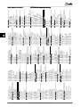
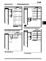
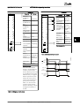
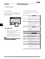
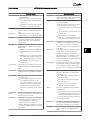
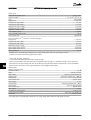
Installation
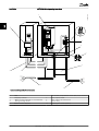
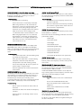
12, 13
-
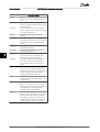
+24 V DC
2 2
18
5-10
[8] Start
19
5-11
[0] No
operation
32
5-14
[0] No
operation
33
5-15
[0] No
operation
27
5-12
[2] Coast
inverse
29
5-13
[14] JOG
20
-
37
-
39
-
42
6-50
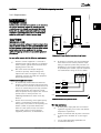
24 V DC supply
voltage. Maximum
output current is 200
mA total for all 24 V
loads. Useable for
digital inputs and
external transducers.
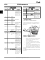
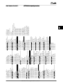
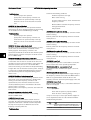
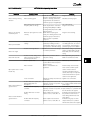
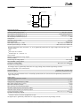
Terminal
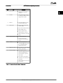
Terminal Description
Digital Inputs/Outputs
Default
Parameter
Setting
Description
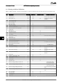
RS-485 Interface. A
control card switch is
provided for
termination resistance.
68 (+)
8-3
69 (-)
8-3
01, 02, 03
5-40 [0]
[0] Alarm
04, 05, 06
5-40 [1]
[0] Running
Relays
Form C relay output.
Usable for AC or DC
voltage and resistive
or inductive loads.
Digital inputs.
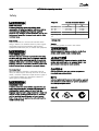
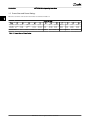
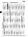
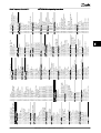
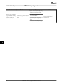
Table 2.3 Terminal Description
2.4.5.3 Wiring to Control Terminals
Selectable for either
digital input or
output. Default setting
is input.
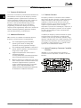
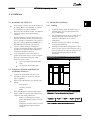
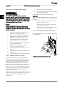
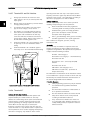
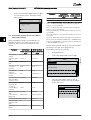
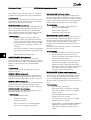
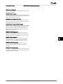
Control terminal connectors can be unplugged from the
frequency converter for ease of installation, as shown in
Illustration 2.16.
130BT306.10
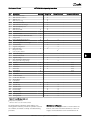
Terminal
Terminal Description
Digital Inputs/Outputs
Default
Parameter
Setting
Description
Common for digital
inputs and 0 V
potential for 24 V
supply.
Safe Torque
Off (STO)
(optional) Safe input.
Used for STO
Analog Inputs/Outputs
Common for analog
output
Speed 0-High
Limit
Programmable analog
output. The analog
signal is 0-20 mA or
4-20 mA at a
Illustration 2.16 Unplugging Control Terminals
maximum of 500 Ω
50
-
+10 V DC
53
6-1
Reference
54
6-2
Feedback
55
-
61
-
10 V DC analog
supply voltage. 15 mA
maximum commonly
used for potentiometer or thermistor.
Analog input.
Selectable for voltage
or current. Switches
A53 and A54 select
mA or V.
Common for analog
input
Serial Communication
18
Integrated RC-Filter for
cable screen. ONLY for
connecting the screen
when experiencing
EMC problems.
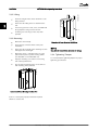
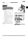
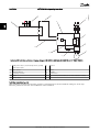
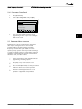
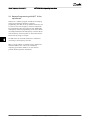
1.
Open the contact by inserting a small screwdriver
into the slot above or below the contact, as
shown in Illustration 2.17.
2.
Insert the bared control wire into the contact.
3.
Remove the screwdriver to fasten the control wire
into the contact.
4.
Ensure the contact is firmly established and not
loose. Loose control wiring can be the source of
equipment faults or less than optimal operation.
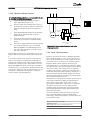
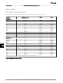
See 10.1 Power-dependent Specifications for control terminal
wiring sizes.
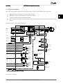
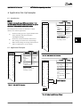
See 6 Application Set-Up Examples for typical control wiring
connections.
MG11AH02 - VLT® is a registered Danfoss trademark