1
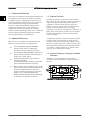
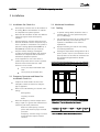
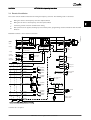
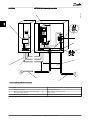
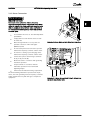
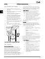
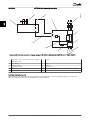
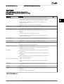
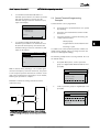
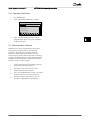
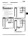
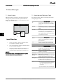
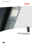
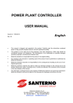
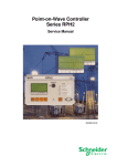
VLT® HVAC Drive Operating Instructions
Installation
In hoisting/lowering applications, it is necessary to be able
to control an electro-mechanical brake:
• Control the brake using any relay output or
digital output (terminal 27 or 29).
•
Keep the output closed (voltage-free) as long as
the frequency converter is unable to ‘support’ the
motor, for example due to the load being too
heavy.
•
Select Mechanical brake control [32] in parameter
group 5-4* for applications with an electromechanical brake.
•
The brake is released when the motor current
exceeds the preset value in 2-20 Release Brake
Current.
•
The brake is engaged when the output frequency
is less than the frequency set in 2-21 Activate
Brake Speed [RPM]or 2-22 Activate Brake Speed
[Hz], and only if the frequency converter carries
out a stop command.
If the frequency converter is in alarm mode or in an overvoltage situation, the mechanical brake immediately cuts
in.
In the vertical movement, the key point is that the load
must be held, stopped, controlled (raised, lowered) in a
perfectly safe mode during the entire operation. Because
the frequency converter is not a safety device, the crane/
lift designer (OEM) must decide on the type and number
of safety devices (e.g. speed switch, emergency brakes etc.)
to be used, in order to be able to stop the load in case of
emergency or malfunction of the system, according to
relevant national crane/lift regulations.
L1
L2
L3
U
V
W
130BA902.10
2.4.5.9 Mechanical Brake Control
Drive
Output
relay
02
2 2
01
Command Circuit
220Vac
Mechanical
Brake
Motor
Shaft
Output
A1
Contactor
Input
A2
Frewheeling
diode
Brake Power Circuit
380Vac
Illustration 2.21 Connecting the Mechanical Brake to the
Frequency Converter
2.4.6 Serial Communication
RS-485 is a two-wire bus interface compatible with multidrop network topology, i.e. nodes can be connected as a
bus, or via drop cables from a common trunk line. A total
of 32 nodes can be connected to one network segment.
Repeaters divide network segments. Note that each
repeater functions as a node within the segment in which
it is installed. Each node connected within a given network
must have a unique node address, across all segments.
Terminate each segment at both ends, using either the
termination switch (S801) of the frequency converters or a
biased termination resistor network. Always use screened
twisted pair (STP) cable for bus cabling, and always follow
good common installation practice.
Low-impedance earth (ground) connection of the screen at
every node is important, including at high frequencies.
Thus, connect a large surface of the screen to earth
(ground), for example with a cable clamp or a conductive
cable gland. It may be necessary to apply potentialequalizing cables to maintain the same earth (ground)
potential throughout the network. Particularly in installations with long cables.
To prevent impedance mismatch, always use the same
type of cable throughout the entire network. When
connecting a motor to the frequency converter, always use
screened motor cable.
Cable: Screened twisted pair (STP)
Impedance: 120 Ω
Cable length: Max. 1200 m (including drop lines)
Max. 500 m station-to-station
MG11AH02 - VLT® is a registered Danfoss trademark
23