1
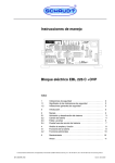
Operating Instruction Manual of Energy Management System
EBL 208 S, Art.-No. 911.470
Seite 1 / 7
Contents
1.
Description
2.
Safety Information
3.
Operating Instructions
4.
Transport, Storage, Installation
5.
Electrical Installation
6.
Power-Up, Shut-Down, Maintenance
7.
Malfunctions
8.
Enclosure
1.
Description
The energy system EBL208 S contains the charging module LAS 1216, the battery monitor module
BW 208, the complete 12V distribution, fused 12V circuits, a connector for a solar regulator and
additional control and monitoring devices.
The charging unit is designed as a primary controlled switch-mode power supply.
This modern design ensures high power output with compact dimensions and light weight.
To operate the energy system and to control the living-area functions including accessories
an instrument panel is compulsory.
1.1
Suitable Accessories (not supplied)
control and switch panel
instrument panel IT 204
solar regulator
LR 1214, art.no 922.202, for solar modules with a total maximum
current of 14A, with 3-p connector and a connecting cable 0.5m.
1.2
Technical Data
1.2.1
General Data
sizes (h x w x d in mm)
130 x 275 x 170 incl. mounting sockets
weight
1.8 kg
cabinet
PA (Polyamid), gentian blue RAL 5010
frontpanel
aluminium, powder painted, light grey RAL 7035
1.2.2
Electrical Data
mains supply
* 230V (+ 10 / - 15%), 47 - 63Hz, safety class 1
power consumption
* 280W
suitable batteries
* 6 cell lead-acid or lead-gel batteries, more than 55Ah
steady load off
living-area battery
* without mains supply, battery alarm 'OFF', a battery voltage
of 12.6V and with IT 204: 0.6mA
load current of alternator's
D+ output by EBL
* approx 0.4A without load at D+ terminal,
see schematic diagram
permissable load...
...on 12V outputs
* maximum current draw up to the fuse rating of each output,
see enclosed schematic diagram
...anti-freeze valve
* max 0.1A
...D+ terminal
* 1A, with D+ input fused by 2A.
note: operating instruction manual is intended for the owner and has to come with the EBL
Schaudt GmbH - Elektrotechnik & App.-bau - 88677 Markdorf - Germany 13.12.2001
Operating Instruction Manual of Energy Management System
EBL 208 S, Art.-No. 911.470
Seite 2 / 7
1.2.2.1 Battery charging ...
... on mains supply
living-area battery:
control system
* thyristor controller
charging characteristic
* IUoU
maximum charging voltage
* 14.3V
charging current
* 16A within mains supply range, electronically limited
floating voltage
* 13.8V, automatic change-over
new charging cycle
(change-over to boost-charge)
* if battery voltage approx < 13.8V, about 5 sec delay
3-phase characteristic:
charging characteristic of EBL 208 S
* boost-charge at 16A
(arithmetic mean, electronically limited)
up to maximum charging voltage,
* then equalize-charge at constant 14.3V
(selectable: 1h duration for lead-acid;
8h duration for lead-gel batteries),
U charge
V
'boost-charge'
I
'equalize'
Uo
'float'
U
14.3
13.8
1h with lead-acid
8h with lead-gel
time
* then automatic change-over to float-charge
at 13.8V.
If due to high loads the 13.8V floating voltage can't be provided the battery charger switches
over from float to boost-charge after a delay of approx. 5 sec.
safety circuits
* overheat protected
* overload protection by electronic current limiting
* short-circuit protected by a FK2 automotive fuse
starter battery:
charging current
* trickle-charge of starter battery with max. 2A
...by solar regulator
max. allowed charging
current (camping battery)
* 14A
...while driving
charging current
* simultaneous charging of starter and living-area battery by alternator,
batteries in parallel by cut-off relay, maximum charging current of
living-area battery by alternator must not exceed 30A.
See block diagram.
1.2.2.2 Battery Monitor Module
switch-off voltage
* 10.5V ±0.1V
minimum switch-on voltage
by 12V main-switch on instrument panel
* 11.0V ±0.1V
note: operating instruction manual is intended for the owner and has to come with the EBL
Schaudt GmbH - Elektrotechnik & App.-bau - 88677 Markdorf - Germany 13.12.2001
Operating Instruction Manual of Energy Management System
EBL 208 S, Art.-No. 911.470
Seite 3 / 7
2.
Safety Information
* The electrical installation of the motorhome has to be in accordance with current DIN-, VDE- and
ISO-regulations. Alterations will endanger the safety of persons and the vehicle.
Due to the above mentioned regulations and safety rules, alterations are therefore prohibited.
* The connection of the EBL to the mains supply has to be in accordance to national installation rules.
* The energy system EBL 208 S must not be modified.
* The connection of the energy system has to be done by qualified personnel only and must be
conform to specifications mentioned in this operating instruction manual:
see instruction manual
section 4.2 'Installation'
section 5
'Electrical Installation'
schematic diagram of EBL 208 S
and in enclosure
* In the following text special notice should be paid to the signs shown below:
CAUTION !
Electrical current hazard warning.
CAUTION !
General hazard warning.
3.
Operating Instructions
3.1
Controls
12V fuses
Pluggable FK2 automotive fuses
battery-type selector switch The mains plug of the energy system has to be taken off prior to
actuating the battery-type selector switch on the frontside of the device.
Eg Seperate vehicle from mains supply.
Before power-up of the energy system this switch has to be selected
according to the type of battery used (lead-acid or lead-gel).
The switch ensures an optimum charge of the connected battery type.
To actuate use a thin tool (eg a pencil tip).
Caution !
An incorrect selected battery-type switch may damage the batteries and there may be an
explosion-hazard caused by detonating gas.
battery cut-off switch
The battery cut-off switch 'Battery' seperates the control and switch board
and the anti-freeze valve of the heater system from the living-area battery,
to inhibit stand-by currents while vehicle is non-operative.
See detail 6.2
'Shut-Down'
Attention !
Please note if anti-freeze valve is deactivated by the battery cut-off switch 'Battery', in
position 'off', the safety-valve of the boiler opens automatically.
note: To reactivate all load after being cut-off by battery cut-off switch 'Battery' or after a battery
change, please actuate 12V main switch on the instrument panel.
12V main switch
on instrument panel
With push-button switch '12V EIN/AUS' all load, except automatic step
and AES-refrigerator, is being switched on and off.
Please refer to instruction manual of the instrument panel.
note: operating instruction manual is intended for the owner and has to come with the EBL
Schaudt GmbH - Elektrotechnik & App.-bau - 88677 Markdorf - Germany 13.12.2001
Operating Instruction Manual of Energy Management System
EBL 208 S, Art.-No. 911.470
Seite 4 / 7
3.2
Relay Functions
battery cut-off relay
This relay seperates the starter and living-area battery when the engine is
not running and if there is no voltage on terminal 'D+'.
Both batteries are connected in parallel and therefore simultaneously charged while engine is running.
main-switch relay
bistable
This relay is controlled by the push-button switch on the instrument panel
'12V EIN/AUS'. It switches off all 12V load, except the automatic step and
the AES-refrigerator.
awning-light relay
The awning-light is operational only with turned on main-switch and if the
engine is not running with no voltage on terminal 'D+'.
refrigerator cut-off relay
This relay controls the power supply of the refrigerator.
The refrigerator gets its power from the starter battery only if the engine is
running and if there is a voltage on terminal 'D+'.
An AES refrigerator is provided from the living-area battery when the
engine is not running.
charging relay battery 1
(starter battery)
This relay automatically provides a 2A trickle-charge to
the starter battery if mains supply is on.
3.3
Battery Monitor Module
The battery monitor compares the voltage of the living-area battery with a reference voltage.
As soon as the battery voltage is lower than 10.5V all 12V load will be switched off.
Only the automatic step and a AES-refrigerator are still provided with power. Short falls (< 2 sec )
below the threshold voltage, due to high inrush currents of connected load do not affect the
automatic cut-off function.
If the automatic shut-down has been triggered due to overload or an insufficiently charged battery
all non-essential load should be switched off.
By actuating the '12V on/off' push-button switch on the instrument panel it may be possible to
reactivate the 12V system for a short period of time.
However, the 12V System can not be switched on if the battery voltage stays under 11.0V.
In any case the living-area battery should be fully recharged as soon as possible.
4.
Transport, Storage, Installation
4.1
Transport, Storage
* The energy system should be stored and transported in a suitable packing and in a dry
environment only.
* Storage temperature range : - 10°C to + 50°C.
4.2
Installation
* The energy system has been designed for wall and floor
mounting.
* It has to be fitted onto a stout and level surface by use of
the four provided mounting sockets.
* The energy system is designed for use in a dry and sufficiently
ventilated environment within a temperature range
of - 10°C to + 45°C.
note: operating instruction manual is intended for the owner and has to come with the EBL
Schaudt GmbH - Elektrotechnik & App.-bau - 88677 Markdorf - Germany 13.12.2001
Operating Instruction Manual of Energy Management System
EBL 208 S, Art.-No. 911.470
Seite 5 / 7
* A minimum distance of 5 cm to the surrounding equipment has to be maintained above and to all sides.
In operation a temperature of max + 45°C at a distance of 2.5 cm to the sides must not be
exceeded.
Caution !
Danger of overheating if distances to equipment
are too short or if ventilation is blocked.
5.
Electrical Installation
* Electrical installation has to be executed by qualified personnel only.
* The device must be used only with a living-area battery.
Caution !
The energy system must not be used without a connected living-area battery,
otherwise connected appliances might be damaged in unfavorable conditions.
* Electrical connection is made on the frontside according to enclosed block diagram.
* For installation purposes, the mains plug or mains supply of the vehicle must be disconnected.
Caution !
Danger of life due to electrical shock or danger of burning with a defective mains
cable, incorrect connection or service work with mains supply on.
* Electrical connection has to be in accordance to the following sequence:
1.
all socket connectors on frontpanel
2.
battery cables at battery terminals
3.
230V mains supply plug
* Disconnection has to be executed vice versa.
* AES-refrigerator fuse
This fuse must be used only in conjunction with a AES-refrigerator
Caution !
The AES-refrigerator fuse must not be used with other refrigerator types.
The battery might get deeply discharged. Battery damage is possible.
5.1
230V Mains Supply
* Mains supply has to be connected to an earthing-contact socket outlet.
* The power supply line must be a H05VV-F 3x1.5 cable.
* For connection, the mains plug or mains supply of the vehicle has to be disconnected.
Caution !
Danger of life due to electrical shock or danger of burning with a defective mains
cable, incorrect connection or service work with mains supply on.
5.2
Batteries, Battery-Sense Cable, Refrigerator and D+ (Alternator)
* Leads have to be fused according to their cross-sections.
Maximum allowed fuse ratings:
batteries
battery 1 for refrigerator sensor cable battery 2
30A
15A
2A
D+ (alternator)
2A
* Fuses need to be installed close to the battery terminals or alternator for short circuit protection
of the leads.
note: operating instruction manual is intended for the owner and has to come with the EBL
Schaudt GmbH - Elektrotechnik & App.-bau - 88677 Markdorf - Germany 13.12.2001
Operating Instruction Manual of Energy Management System
EBL 208 S, Art.-No. 911.470
Seite 6 / 7
* The negative pole of the living-area battery has to be connected to the negative pole of the starter
battery externally.
Caution !
Danger of burning because of incorrect connection and fusing.
* The energy system has to be used exclusively on 12V power systems with rechargeable 6-cell leadacid or lead-gel batteries.
Caution !
Unsuitable batteries will be damaged.
* Batteries have to be mounted in sufficiently ventilated areas or must be fitted with vent lines.
Please refer to installation instructions of the battery manufacturer.
Caution !
Exploding hazard by detonating gas with defective batteries, defective energy system
or at too high battery temperature (>30°C).
* The refrigerator input cables 'battery 1 for refrigerator' and 'negative battery 1 for refrigerator' to the
energy system have to be wired seperately from other battery cables to the battery terminals.
Attention !
Without separately wired refrigerator and battery cables an optimum charge of the
living-area battery can not be achieved.
5.3
12V-Load
* The choice of battery cable size dimensions has to comply with EN 1648-1 or –2.
Maximum current drain of the load must not exceed the respective fuse rating.
6.
To Put Into Operation, Shut-Down, Maintenance
6.1
To Put Into Operation
* Prior to power-up special attention must be paid to:
1.
Properly connected living-area battery
2.
Correctly selected battery-type switch. See section 3.1 'Controls'.
3.
AES-fuse inserted only if a AES-refrigerator is used.
* Power-up procedure:
1.
Turn battery cut-off switch 'Battery' into 'on' position.
See user's manual section 3.1 'Controls'.
2.
To reactivate the system after a cut-off by battery cut-off switch or after a battery change, please
actuate 12V main switch on the instrument panel.
6.2
Shut-Down
* Before long periods of nonusage of the motorhome (eg during wintertime), the living-area battery
should be disconnected from the 12V system. Disconnect cables at the battery terminals.
1.
2.
Switch off 12V main-switch on instrument panel
Turn battery cut-off switch on energy system into 'off' position. See section 3.1 'Controls’.
Caution !
Please note, the anti-freeze valve of the boiler opens automatically if vehicle is shut
down by the battery cut-off switch 'Battery'.
note: operating instruction manual is intended for the owner and has to come with the EBL
Schaudt GmbH - Elektrotechnik & App.-bau - 88677 Markdorf - Germany 13.12.2001
Operating Instruction Manual of Energy Management System
EBL 208 S, Art.-No. 911.470
Seite 7 / 7
* Before and after long periods of nonusage (eg. during wintertime), the vehicle should be hooked
up to mains supply to fully recharge the batteries for a minimum of 12 hours (80Ah battery) or
16 hours (160Ah battery).
Caution !
To prevent battery damage the battery should be fully charged before shut-down
of the vehicle.
Note:
A recharge of the batteries by the built-in charging unit, by solar regulator or by alternator
is still possible even if battery cut-off switch is off.
6.3
Maintenance
* The energy system EBL 208 S is maintenance-free.
* For cleaning use a soft moisturized cloth with a mild detergent. Do not use methylated spirit,
paint thinner, etc. Liquids must not be allowed to get into the cabinet.
7.
Malfunctions
* If due to high surrounding temperature or bad ventilation the EBL gets too hot, the charging current will
be decreased automatically. However, overheating should in any case be prevented.
* Should repairs be necessary, please contact the service department of Schaudt GmbH,
ph. 0049-(0)7544-9577-16, eMail: [email protected]
* If it is not possible to see the manufacturer for service (eg being overseas), necessary repairs can be
carried out by a qualified workshop.
* Unqualified repairs enforce expiration of warranty. The manufacturer Schaudt GmbH disclaims it's
liability and is therefore not liable to resulting damages.
8.
Enclosures
To this operating instruction manual belongs the enclosed schematic diagram and the drawing
of the front view of the energy system EBL 208 S, art.no 911.470.
This operating instruction manual with all it's enclosures must be delivered together with the
energy system EBL 208 S, art.no 911.470.
It has to be part of the instruction manual if it is part of a system installed in a motorhome.
8.1
EC declaration of conformity
We hereby certify that the type of construction of the energy management system EBL 208 S
corresponds accordingly to appropriate provisions:
EC low-voltage guide line
Electromagnetic compabitibility guide line
73/23/EWG i.d.F. der Änderung vom 22.07.93
89/336/EWG mit Änderung 92/31/EWG
Employed standards and technical specifications, particularly:
DIN EN 60335-1:1994 +A11+A1+A12+A13+A14
DIN EN 60335-2-29:1996 + A11
DIN EN 50081-1:3.1993
DIN EN 50082-1:3.1993
DIN EN 61000-3-2:10.1998
The EC declaration of conformity in original is available and can be looked at any time.
Manufacturer: Schaudt GmbH, Elektrotechnik & Apparatebau
Address:
Daimlerstraße 5
88677 Markdorf
Germany
note: operating instruction manual is intended for the owner and has to come with the EBL
Schaudt GmbH - Elektrotechnik & App.-bau - 88677 Markdorf - Germany 13.12.2001