1
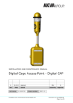
SolarMate 36/48V Solar Battery Charger Controller INSTALLATION AND OPERATION MANUAL Version 1.0E PREFACE This manual contains important information regarding Installation and safe operation of this unit. Notice: The contents of this manual are bound to change without prior notice. We cannot assume responsibility for errors in this manual or consequences thereof. However should any error be detected, we would be grateful if you could inform us. 2 SAFETY INSTRUCTIONS Risk of Electric Shock Direct Current (DC) sources are connected to this device. To avoid risk of electric shock during maintenance or installation please ensure that all DC connections are disconnected. Risk of Electric Shock When PV module or panel is exposed to light, it starts to supply high DC voltage. Be sure to turn off DC switch before commencing the maintenance, and make sure the cables from PV panel are properly sealed after disconnection. Risk of Electric Shock After disconnecting the power sources, the product will continue to discharge at DC terminal for a short period. Before commencing maintenance, please wait for at least 2 minute after the power is disconnected. Authorized Personnel Only Only authorized personnel are allowed to install, commission and repair the product. Warning If the product is used in a manner which is not covered by the scope of warranty, the protection provided by the product may be impaired. 3 SCOPE OF WARRANTY The product comes with a standard 1-year warranty. This warranty includes all defects of design, components and manufacturing. The Warranty is void and does not cover any defects or damages caused by any of the following circumstances: Seal on the product is broken The product has been misused, neglected, or abused Improper transportation and delivery The product has been used or stored in conditions outside its electrical or environmental specifications The product has been used for purposes other than for which it was designed The product has been used outside its stated specifications, operating parameters and application Acts of third parties, atmospheric discharges, excess voltage, chemical influences, natural wear and tear and for loss and damage in transit Improper testing, operation, maintenance, adjustment, repair, or any modification of any kind not authorized in writing by the supplier The product has been connected to other equipment with which it is not compatible Use and application beyond the definition in this manual Application beyond the scope of applicable safety standards or grid codes Acts of nature such as lighting, fire, storm, flood, vandalism and etc. The right to repair and/or replace the defective product is at the supplier’s sole discretion. Any warranty claim shall be asserted in writing to the supplier within 5 working days after notice of product failure. The supplier is not responsible for damages beyond the scope of this warranty. 4 Table of Content 1. 2. 3. PRODUCT OVERIVEW ..................................................................................................6 1.1 Product Outlook .................................................................................................6 1.2 Function of Major Parts ......................................................................................6 1.3 Identify the Product ............................................................................................7 1.4 Scope of Delivery ................................................................................................7 1.5 Typical Applications ............................................................................................8 1.6 Key Features .......................................................................................................8 INSTALLATION ..............................................................................................................9 2.1 Mount the Product on the Wall ..........................................................................9 2.2 Connection of Wires .........................................................................................10 2.3 Connect the Grounding Wire ............................................................................12 2.4 Commissioning .................................................................................................12 OPERATION ................................................................................................................13 3.1 Maximum Power Point Tracker (MPPT) ............................................................13 3.2 3-stage Charging Control ..................................................................................13 3.3 Equalization Charge ..........................................................................................15 3.4 Photovoltaic Charge and Load Control .............................................................15 3.5 PV Panel Disconnection during Night Time ......................................................15 3.6 Over Temperature Protection ...........................................................................16 3.7 LED Status and Corresponding Operation Status .............................................16 4. SPECIFICATION ...........................................................................................................17 5. TROUBLESHOOTING ..................................................................................................18 6. DISPOSAL ...................................................................................................................19 5 1. PRODUCT OVERIVEW SolarMate 36/48V is a solar battery charger controller with built-in MPPT (Maximum Power Point Tracker) for PV panel and 24A charging capability for various types of leadacid batteries. 1.1 Product Outlook Front View Side View Bottom View 1.2 Function of Major Parts Power LED Charging Mode LED Battery Selector Load Terminals Battery Terminals PV Terminals 6 1.3 Identify the Product Each SolarMate 36/48V is assigned with a unique serial number which can be found in the rating label located at the side cover as shown below. Please report this serial number to the service representative when in need of service. In the example below, the serial number (S/N) is 1310MPPTSSSSPSC. Product Serial Number (S/N) 1.4 Scope of Delivery Screw for Terminal Cover x4 Plastic Terminal Cover Wall Mounting Screw x3 Description Quantity SolarMate 36/48V 1 Plastic Terminal Cover 1 Screw for Terminal Cover 4 Wall Mounting Screw 3 Screw Anchor 3 Screw Anchor x3 7 1.5 Typical Applications SolarMate 36/48V can be connected with PV panel which supplies DC input power, and convert the power to either supply various DC loads or charge batteries with optimized efficiency. A typical application is shown in the diagram below. DC Loads PV Panel Batteries SolarMate 36/48V Example of Typical Application 1.6 Key Features Able to supply power to DC loads Built-in MPPT (Maximum Power Point Tracker) Lightning protection 3-stage battery charging control (bulk, absorption, and float) Overload protection Protection for reversed polarity of PV panel and batteries 8 2. INSTALLATION 2.1 Mount the Product on the Wall To mount the product on the wall, please follow the steps below: 1. Select a solid, nonflammable wall which can withstand the weight of the product. The product is designed for indoor use so the installed location shall not be exposed to direct sunlight or rainfall. 2. Mark the location of 3 screw holes on the wall according to the distance specified in the diagram below. 3. Drill the screw holes at the marked locations. 4. Insert three screw anchors. 5. Place the product on the wall and align it with the screw holes. 6. Use three screws to fix the product on the wall as shown in the diagram below. Screw Holes Unit: mm WARNING! Please install the product in a dry, protected location which is away from high temperature, direct water spray, moisture of salt water and corrosive gas. Improper installed environment will result in void of warranty. 9 2.2 Connection of Wires The wires from PV panels, batteries and DC loads shall be connected to the terminal block which can be found by opening the cover in the bottom as shown below. It’s recommended that single-core wires be used and the gauge of the wires shall be within the range AWG 20 ~ AWG 6. Before connecting the wires from PV panel, it’s important to conduct polarity check by using a multi-meter. Multi-Meter PV+ PV- WARNING! The terminals of PV panel contain high DC voltage while exposing to light. It’s strongly recommended that a disconnect device shall be installed between the PV panel and the product so that the DC power can be disconnected while connecting the wires. The batteries shall be configured according to its charging characteristics so as to match the setting on the Battery Selector (please refer to Section 3.2 for details). 10 Given that the maximum charging current is 24A, the total capacity of batteries shall be greater than 80Ah. WARNING! Installation must be performed with care for the high battery voltage in series. Do NOT place anything between battery cable ring terminals and terminals on the product. The terminal screw is not designed to carry current. WARNING! Please DO NOT install the product in a sealed cabinet together with the batteries which might emit corrosive gas and damage the product. It’s recommended that a conduit and conduit adapter with locknut, which can be easily purchased in hardware store, shall be used for the protection of wires. Inner thread of the plastic cover is M35*1.5P and ¾ inch conduit is recommended. A plastic terminal cover is delivered together with the product for fitting the conduit as shown in the diagram below. 1. Remove sheet-metal terminal cover A and B from the chassis. 2. Assemble the conduit adapter and locknut to the plastic terminal cover, and then assemble the plastic terminal cover onto sheet-metal terminal cover B with 4 screws. 3. Put the wires through the conduit, conduit adaptor, plastic terminal cover, locknut and sheet-metal terminal cover B. 4. Connect the wires to the terminal block with torque 1.76 N-m. 5. Insert the tenon of sheet-metal terminal cover B into the slot below the terminal block, and then fix the sheet-metal terminal cover B onto the chassis with 2 screws. 6. After all conduits are assembled, check if wires are fixed well on the terminal block. 7. Fix the sheet-metal terminal cover A onto sheet-metal terminal cover B with 2 screws. Sheet Metal Terminal Cover A Sheet Metal Terminal Cover B Locknut Conduit Adapter Conduit Plastic Terminal Cover 11 2.3 Connect the Grounding Wire WARNING! The product is classified as Class I equipment which requires grounding on the enclosure to prevent the user from electric shock. A grounding SEMS screw can be found on the right side of enclosure. Remove the grounding screw and fix the grounding wire with the screw as shown below. Grounding Wire Grounding Screw 2.4 Commissioning After installing the product by following the steps in Section 2.1~2.3, conduct the first commission with the following steps: 1. 2. 3. 4. Check if all the wires are connected correctly, especially the polarity. Set the Battery Selector according the batteries used (please refer to Section 3.2). Switch on the DC power from battery and then the DC power from PV panel. If the DC voltage from PV panel is larger than battery voltage, the Power LED will be on. 5. Power LED shall be on constantly if no abnormal condition is detected. 12 3. OPERATION 3.1 Maximum Power Point Tracker (MPPT) PV panel’s output power is mainly subject to the illumination. However under given illumination, the output power can still be maximized with proper control. MPPT serves the function to ensure maximum power is generated by the PV panel at any illumination. MPPT works automatically as long as the PV panel voltage is sufficient, so as to ensure the batteries are charged by PV power at optimized efficiency. 3.2 3-stage Charging Control Intelligent charging control can not only maximize the capacity of batteries but also prolong their lifetime. The product’s charging control is designed to be 3 stages: 1. Bulk Charge Stage In this stage, the battery voltage is low and is charged with increasing charging voltage and maximum constant charging current. 2. Absorption Stage In this stage, the charging voltage will be hold at bulk voltage and charging current gradually decreases. 3. Floating Charge Stage In this stage, the battery is deemed fully charged. Charging voltage and current are both hold at a constant level to maintain the battery capacity at full level. Bulk Charge Stage Absorption Stage Floating Charge Stage Bulk Voltage Constant Voltage Charging Voltage Charging Current Floating Voltage Constant Current Time 3-stage Charging Control 13 Different types of battery require different setting on Bulk Voltage and Floating Voltage. The setting can be done by the Battery Selector according the table below. Use a flat screw driver to rotate the switch until the recess points to the desired number Switch Position Battery Type/ Function Floating voltage (V) Bulk/ Equalize voltage (V) 0 Equalization setting 39.6 *45 1 Deep Cell Lead Acid 2 39.9 45 2 Deep Cycle Lead Acid 1 40.2 43.8 3 Gel Cell 40.5 42.3 4 PcCa-lead Calcium 39.6 42.9 5 Equalization setting 52.8 *60 6 Deep Cell Lead Acid 2 53.2 60 7 Deep Cycle Lead Acid 1 (Default Setting) 53.6 58.4 8 Gel Cell 54 56.4 9 PcCa-lead Calcium 52.8 57.2 Nominal Battery Voltage 36-Volt 48V-Volt 14 3.3 Equalization Charge Equalization charge is a special charging mode. After a series of repeated charge/discharge cycles, the cells in the battery might become unequal in terms of voltage and discharge current, mainly because of accumulated sulfate on the surface and stratified electrolyte, and resulted in capacity decrease. Equalization charge can mitigate the problem and prolong the battery life. Please follow the steps below to perform Equalization Charge, 1. Remove all DC loads connected to the product. 2. Remove all battery vent caps. 3. Make sure the battery’s water is at normal level. Use only distilled water for filling batteries. 4. Set the BATTERY SELECTOR switch to position “0” or “5”. 5. Reset the BATTERY SELECTOR to the appropriate setting according to the type of batteries after the Equalization Charge is completed. Frequency of Equalization Charge Equalization charge shall be performed every month or two depending on the usage of battery. 3.4 Photovoltaic Charge and Load Control SolarMate 36/48V can regulate up to 24A continuous current at 36/48V for charging batteries. In the meantime it can provide maximum 7A current to DC loads. SolarMate 36/48V detects the battery voltage and determines when the DC loads shall be disconnected under over-discharge or over-loading conditions, and reconnected when battery voltage is recovered to higher level. DC loads are disconnected when the battery voltage is below LVD (“Low Voltage Disconnect) point. DC loads will be reconnected when the battery voltage reaches LVR (“Low Voltage Reconnect”). LVD and LVR setting can be found in product specification. 3.5 PV Panel Disconnection during Night Time To prevent the PV panel from reversed leakage power, SolarMate 36/48V automatically disconnect the PV panel during night time. 15 3.6 Over Temperature Protection SolarMate 36/48V can charge batteries at full capacity when the ambient temperature is below 50℃. When the temperature goes to 50-65℃, SolarMate 36/48V will perform power de-rating by limiting its output power. If the temperature goes beyond 65℃, the output will be stopped and the LED status will indicate over-temperature fault. 3.7 LED Status and Corresponding Operation Status The operation status of SolarMate 36/48V can be told by checking the status of 2 LEDs: Power LED and Charge Mode LED. POWER LED CHG. MODE LED Operation Mode Description Green (on) Red (on) Green (on) Orange (on) Green (on) Green (on) Green (on) Red (blink) Green (on) Orange (blink) Green (on) Green (blink) Green (blink) Red (on) Over loaded Green (blink) Orange (on) Over temperature (>65℃) Green (blink) Red (blink) Green (blink) Orange (blink) Green (blink) Off Off Orange (blink) VBAT: Battery voltage LVD: Low voltage disconnect point LVR: Low voltage recovery point Charging (VBAT<LVD) Normal Charging (LVD<VBAT<LVR) Charging (VBAT>LVR) De-rating (50-65℃) Fault Charging (VBAT<LVD) Charging (LVD<VBAT<LVR) Charging (VBAT>LVR) PV over voltage PV under voltage Battery over voltage Battery under voltage 16 4. SPECIFICATION Battery voltage setting 36VDC 48VDC Rated charge current 24A Load current 7A Input voltage range 40-150VDC Max. PV open circuit array voltage Max. recommended input power (W) 150VDC 900 1200 Typical idle consumption < 10mA 14A >5s 10.5A >20s Overload protection (DC load) 8.75A (de-rating) Bulk charge 43.8V(default) 58.4V(default) Floating charge 40.2V(default) 53.6V(default) Over charge disconnection 47.4V 63.2V Over charge recovery 42.0V 56.0V Over discharge disconnection 32.4V 43.2V Over discharge reconnection 36.9V 49.2V Low voltage reconnect 36.9 ± 0.3 VDC 49.2 ± 0.3 VDC Low voltage disconnect 32.4 ± 0.3 VDC 43.2 ± 0.3 VDC Ambient temperature 0-50℃ (full-rating) 50-65℃ (de-rating) Altitude <3000 m Cooling Nature Cooling Protection class IP20 Terminal size (fine/single wire) AWG # 20 ~ 6 Dimension (D x W x H) 124*220*311 Net Weight (kg) 5.4 17 5. TROUBLESHOOTING Problem No response (Both POWER LED and CHG. MODE LED are off) LEDs indicate “Over Temperature” fault It takes too long to charge the battery to full level. Possible Cause No power from battery (note: system power is supplied by battery only) Suggested Action Check if the battery is connected correctly. Ambient temperature is too high Improve the ventilation. Check if the PV input voltage is normal. Check if the ambient temperature is higher than 50℃. If yes, improve the ventilation. Check the PV panel’s condition and replace it if needed. Check if the PV panel’s cables are connected correctly. The unit has entered into “de-rating” mode due to high temperature PV panels are deteriorated PV- cable is wrongly connected to BAT- 18 6. DISPOSAL In the event the product reaches the end of its service life, please contact the local dealer for disposal instructions. The product must not be disposed of with the household waste. Disposal of the product at the end of its service life shall be done in accordance with applicable disposal regulations for electronic waste. 19