1
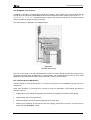
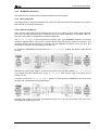
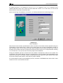
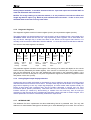
Citect for Windows
Driver Specification Extract
INTERBUS Driver
Author:
Date:
Dominic Cioccarelli
15/12/1997
25/3/98
Trevor
- Testing
Hudson
20/7/98
Stephen Burman Post
testing
changes
Driver Design Specification
Contents
2.
4.
TARGET DEVICE(S) AND PROTOCOL
4
2.1 Introduction
4
2.2 Device Manufacturer
4
2.3 Device Definition
4
2.4 Communications Method
4
2.5 Communications/Hardware Configuration
5
2.5.1
The Remote Bus
6
2.5.2
INTERBUS I/O Modules
8
2.5.3
Wiring Diagrams
8
2.5.4
I/O Device Settings
10
2.5.5
Software Setup
10
2.6 Special Requirements
10
2.7 Maximum Request Length
12
USER INTERFACE
13
4.1 Introduction
13
4.2 Driver Name
13
4.3 Boards Form
13
4.3.1
Board Type
13
4.3.2
Address
13
4.3.3
IO Port
13
4.3.4
Special Opt
13
4.4 Ports Form
13
4.4.1
Baud Rate
13
4.4.2
Data Bits
13
4.4.3
Stop Bits
13
4.4.4
Parity
13
4.4.5
Special Opt
14
4.5 IO Devices Form
14
4.5.1
Protocol
14
4.5.2
Address
14
4.6
14
Pulldown lists Help
14
4.7 IO Device Variable Types
16
4.7.1
Format
INTERBUS.DOC
16
2
Driver Design Specification
4.7.2
Explanation
16
4.7.3
Notes on the relationship between tag addresses and terminal addresses on the devices
17
4.7.4
Automatic Data Conversion
17
4.7.5
Diagnostic Registers
18
4.7.6
Analog/Digital Output display behaviour
18
4.7.7
INTERBUS.DBF
18
4.8 PROTDIR.DBF
19
4.9 Parameters and INI options
19
4.9.1
Standard Parameters
19
4.9.2
Driver Specific Parameters
20
4.10
Driver Specific Errors
22
4.11
Driver Error Help
26
4.12
Debug Messages
30
4.12.1
5.
Initialising
4.13
Stats Special Counters
31
4.17
Hints and Tips
33
TROUBLESHOOTING
34
5.1 Startup Errors
34
5.2
34
Run-time Errors
34
5.3 Debug Window Errors
35
5.3.1
Introduction
35
5.3.2
Common Errors
35
5.4 Hardware Alarm Page Errors
9.
30
REFERENCES
9.1 References
INTERBUS.DOC
37
38
38
3
Driver Design Specification
2.
2.1
Target Device(s) and Protocol
Introduction
This section defines the types of I/O Devices that are targeted by this driver.
2.2
Device Manufacturer
Headquarters:
Phoenix Contact GmbH & Co.
Postfach 13 41,
32819 Blomberg
Germany
Tel:
+49 52 35 300
Fax: +49 52 35 33 11 99
US office:
Phoenix Contact GmbH & Co
PO Box 4100
Harrisburg
PA 17111-0100
U.S.A
Tel:
+1 717 944 1300
Fax: +1 717 944 1625
2.3
Device Definition
This driver supports any device that can be connected to an INTERBUS network. This includes analog
and digital I/O modules and even PLCs (with the addition of an appropriate INTERBUS adaptor).
2.4
Communications Method
At a physical level, the RS-485 protocol is used for communication on the remote bus. The I/O devices
are connected to the bus in a ring configuration, the exact details of which are discussed in section
Error! Reference source not found.. A proprietary controller board must be used within the Citect PC
as much of the protocol interpretation is done by the hardware on this board. The protocol cannot be
implemented purely in software due to its real time requirements. Currently, Citect is guaranteed to
support the IBS PC ISA SC/I-T board, although older boards such as the IBS PC CB/I-T or IBS
PC CB/COP/I-T may be supported in the future.
Citect communicates with the controller via an area of shared memory, called Multi-Port Memory
(MPM). This shared memory is further divided into a Data Transmission Area (DTA), Signal Area (SGA)
and a Mailbox Area (MXA).
The MPM size and location depend on the host configuration. Luckily, Citect doesn’t need to know these
details as an API provided by the manufacturer handles all communications with the shared memory.
This API allows bilateral transmission of data through a mailbox type interface. The installation of this
API is discussed in section 0.
INTERBUS.DOC
4
Driver Design Specification
2.5
Communications/Hardware Configuration
Network Topology Overview
Terminal I/O is connected to the controller card by means of a bus topology, which is presented in the
diagram below:
Local Bus
Remote Bus
Figure 0.1
INTERBUS Topology
The remote bus connects the interface board in the PC with the remote bus terminals and the remote
bus terminals with each other. The bus terminals are shown with a BS designation on the diagram
above and are used to convert remote bus signals into local bus signals. The local bus is used for
communications between devices on a segment. Otherwise stated, bus terminals provide a way of
breaking up the remote bus into segments that use a local bus for communication.
The Controller Board
The INTERBUS distributed I/O system is connected to the controlling device by means of a controller
board. There are two different types: passive and active connection. The controller board used by Citect
implements a passive connection, i.e. the neutral representation of I/O data in a memory area
accessible to the controller, which is better than active connection in that it requires little software
intervention on the part of the control system. Standard tasks performed by an INTERBUS controller
board are:
• the detection of the bus configuration
• the control of the cyclical INTERBUS protocol
• the transmission of I/O data from the transfer memory to the INTERBUS modules and vice versa
• the monitoring of the bus system
• the fault detection and localisation
• the activation of INTERBUS-specific operating and display units
INTERBUS.DOC
5
Driver Design Specification
2.5.1
The Remote Bus
The remote bus covers long distances within a system. The total length of the remote bus may be up to
12.8 km (measured from the controller board to the last remote bus device). For this, the entire remote
bus is divided into individual bus segments with a maximum length of 400 m.
The remote bus has the following specifications:
• Max. length of a remote bus segment 400 m
• Max. bus cable length between:
-
controller board of the first remote bus device 400 m
-
controller board of the last remote bus device 12.8 km
• Transmission method RS 485
• Transmission media single-shielded two-wire line
The Local Bus
The local bus is a local branch of the remote bus. The local bus allows the variable and low-cost
installation of a decentralised substation, preferably within the switch cabinet. Like the installation
remote bus, the local bus line also carries supply lines for local bus devices and initiators connected to
them. The local bus is coupled to the remote bus via a BK module. In the local bus itself, different I/O
modules can be combined with one another. Local bus modules cannot be integrated in the remote bus
or installation remote bus. Conversely, it is not possible to use remote bus devices on the local bus.
Note: The local bus is abbreviated with LB.
The local bus has the following specifications:
• Max. total current consumption 0.8 A
• Max. cable length between:
-
the BK module and the first local bus device 1.5 m
-
two devices 1.5 m
-
the BK module and the last local bus device 10 m
• Max. number of I/O devices in the local bus 8
• Transmission CMOS level
INTERBUS.DOC
6
Driver Design Specification
The INTERBUS Tree Structure
In addition to providing a remote and localised bus topology, cable routes can be further optimised by
introducing a tree structure. INTERBUS BK units with a remote bus branch feature (such as the IBS IP
CBK or IBS ST 24 BK RB-T) provide a branch output to the next remote bus level. This branch allows
further I/O stations as well as further branching.
The tree structure is depicted in the diagram below:
Figure 0.2
INTERBUS Branching
The use of branching is not only advantageous in terms of easier cabling but also with respect to the
functional requirements of an application. A tree structure can implement branch lines for drum cable
applications and individual branches can be switched in and out of the network.
Bus Terminal Module (BK Module)
The BK module is a remote bus device. It connects the local bus or the installation remote bus to the
remote bus.
Other than providing a conversion from remote to local bus standards, a BK module provides the
following services:
• Supplying the I/O modules connected to the local bus or installation remote bus with voltage.
• Regenerating data in the remote bus.
• Electrical isolation of the remote bus segments from each other.
• Switching the interfaces to the local bus and the outgoing remote bus on and off, a function that is
initiated by the INTERBUS master.
INTERBUS.DOC
7
Driver Design Specification
2.5.2
INTERBUS I/O Modules
The respective I/O modules link the sensors/actuators to the bus system.
2.5.3
Wiring Diagrams
The cabling used not only differs between the remote bus and local bus but also depends on the type of
Bus Terminal or I/O device being used.
2.5.3.1 Remote Bus Wiring
The connector which plugs into the interface card in the PC is always a 9 pin male D type connector.
From here, the cable will terminate in a different type of connector depending on the specific BK unit.
Only the most common configurations will be discussed here.
The IBS ST 24 BKM-T is a bus terminal for the green “lego” type INTERBUS modules. This device
should be supplied with a 8 way screw connector which plugs into the top, remote IN connector. The
connector Remote Bus IN connector on the BK unit will designate the letters A-E for the pins. The
Remote Bus Out connector will designate the letters F-L.
To connect the INTERBUS interface card to an IBS ST 24 BKM-T module, the following cable should
be used:
Note that this cable is also used for connecting the green Lego type BK modules (IBS ST 24 BKM-T)
to the larger silver BK modules such as the IBS 24 BK-T which have a 9 pin D connector for the
remote bus out.
In order to connect two IBS ST 24 BKM-T together, a cable with two COMBICON connectors must
be used, and is presented in the diagram below:
Obviously, the output of the lower numbered device (pins G-L) will be connected to the input of the
subsequent BK module (pins A-E).
INTERBUS.DOC
8
Driver Design Specification
The final option in IBS ST 24 BKM-T module wiring is the connection to a larger IBS 24 BK-T
module. These larger BK modules use 9 pin D type connectors for local bus wiring (just like the
controller board). The cable which should be used to connect a IBS ST 24 BKM-T to a IBS 24
BK-T module is presented below:
2.5.3.2 Local Bus Wiring
The local bus wiring, as mentioned previously, is used to connect the BK modules to the actual I/O
units. In the case of the green “Lego” type units, a 5-way ribbon type cable is used to connect
subsequent I/O units together and to connect them to the initial BK unit.
In the case of the larger silver BK units (such as the IBS 24 BK-T), 15 pin D connectors are used to
connect the BK unit to the I/O modules and for interconnections between the I/O modules.
The pinouts for this cable are given below:
Figure 0
“15 pin D” type localbus Cable
INTERBUS.DOC
9
Driver Design Specification
Signal Name
15 pin Male
Colour
1
15 pin
Female
1
UVO
UVO
2
2
white-green
jumper 3-4
3
-
SLI
5
5
white
CKI
6
6
yellow
CRI
7
7
pink
DI
8
8
violet
COM
9
9
blue
COM
10
10
red-blue
RES
11
11
grey-pink
SLO
12
12
brown
CKO
13
13
green
CRO
14
14
grey
DO
15
15
black
red
Table 0
Connections for “15 pin D” type localbus Cable
2.5.4
I/O Device Settings
I/O device settings are very much dependant on the I/O module used. Normally, modules are set by
writing to a particular register rather than by changing DIP-switch settings. If an I/O device needs to be
configured by writing to a register, Citect can be programmed to do this upon startup.
2.5.5
Software Setup
No special configuration should be needed to initiate communications with any of the I/O units as all
hardware on the ring will be initialised by Citect during start-up. In some cases, various I/O modules will
be required to be set to a particular mode of operation, depending on the project. This should be done
from within the Citect project by writing to a tag that is associated with the register in the module that
sets the mode of operation. Note that this action could either performed by a CiCode function which is
executed upon start-up, or when a certain page is accessed.
2.6
Special Requirements
Citect requires the installation of a driver in order to access controller card. This software is supplied by
the manufacturer, Phoenix Contact. The driver consists of a kernel level VxD which communicates
directly with the hardware and a user level DLL which is used for communications with Citect (via the
INTERBUS driver).
INTERBUS.DOC
10
Driver Design Specification
To install the driver, it is necessary to run the SETUP.EXE program in the WINNT directory of the
Software Windows Driver disk. Citect has been tested with version 1.01 of this driver, so this and all
later revisions of the driver should also work.
Upon commencing the installation of the driver, you will be presented with the following screen:
Diagram 0.1
Driver Installation
Note that the board number specified above will be the same as the board number specified during the
configuration of the “boards” form in Citect. Thus, Citect must carry out this configuration process for
each controller card in the PC before that card will be available for use. Note that Citect has no way of
knowing which boards have been configured and will thus allow access to un-configured board, resulting
in a run-time error. It is up to the user to ensure proper driver installation.
During the installation process, ensure that the I/O address corresponds to that set on the board. The
configuration of the base address is shown in the Diagram 0.2. The I/O address and base address must
also be set. Normally, it is simply a matter of selecting the default values for a given board. Ensure that
the chosen interrupt value doesn’t conflict with any other hardware.
For further details concerning the installation process, consult the “INTERBUS Quick Start Guide”, order
number 27 47 87 9 from Phoenix Contact.
INTERBUS.DOC
11
Driver Design Specification
100
on
on
1 2 3 4 5 6 7 8
on
1 2 3 4 5 6 7 8
on
1 2 3 4 5 6 7 8
on
1 2 3 4 5 6 7 8
108
1 2 3 4 5 6 7 8
8
10
20
40
80
100
200
120
Default
Base address setting
3F8
Example Base Addresses
Diagram 0.2
I/O Address Configuration
The installation procedure will create a directory called “IBS Driver”. Under this directory, there is a
sub-directory called “LIB”. It is necessary to copy the file IBDDIWNT.DLL from this directory to the
CITECT/BIN directory. You can either use a DOS window or the Windows Explorer to complete this
operation.
2.7
Maximum Request Length
Only the number of registers in the I/O device being accessed limits the maximum request length. It will
be set to 1024 bits as this implies 64 x 16 bit registers. All INTERBUS devices have less than 64
registers. This assumption may need to be modified.
INTERBUS.DOC
12
Driver Design Specification
4.
4.1
User Interface
Introduction
This section defines how the user will see the driver. This relates directly to how the Citect forms need
to be filled out and any special INI options. For the kernel, the debug trace messages and the
Stats.Special counters are documented.
4.2
Driver Name
INTERBUS
4.3
Boards Form
4.3.1
Board Type
INTERBUS
4.3.2
Address
N/A
This doesn’t work I had to use 0
4.3.3
IO Port
1–8
4.3.4
Although ports 1 – 8 are acceptable, the board specified must have been previously
configured as described in section 0.
Special Opt
N/A
4.4
Ports Form
The ports form is not of any use for this driver as there is only one port per board.
4.4.1
Baud Rate
N/A
4.4.2
Data Bits
N/A
4.4.3
Stop Bits
N/A
4.4.4
Parity
N/A
INTERBUS.DOC
13
Driver Design Specification
4.4.5
Special Opt
N/A
4.5
IO Devices Form
N/A
4.5.1
Protocol
INTERBUS
4.5.2
Address
Format:
S.P
(segment.position)
The two numbers in the unit address represent a standard INTERBUS address: the segment number, S,
(the number of the BK unit at the beginning of a local bus segment) and the position within the segment,
P. The address format can be seen in the diagram below:
If the addressing is adversely affected due to the insertion of a new module between existing units, it is
simply a matter of changing the mapping between the I/O device name and the address in the I/O
devices form of the Citect Project Editor. In the example above, if we inserted a new module between
modules 4.1 and 4.2, then it would be necessary to modify the I/O device names previously assigned to
addresses 4.2 and 4.3 to refer to their new addresses: 4.3 and 4.4 respectively.
4.6
Pulldown lists Help
The following entries should be included in the Citect HELP.DBF spec file.
TYPE
DATA
FILTER
ADDRESS
0
INTERBUS
INTERBUS.DOC
14
Driver Design Specification
BOARDTYPE
INTERBUS
IOPORT
1
INTERBUS
IOPORT
2
INTERBUS
IOPORT
3
INTERBUS
IOPORT
4
INTERBUS
IOPORT
5
INTERBUS
IOPORT
6
INTERBUS
IOPORT
7
INTERBUS
IOPORT
8
INTERBUS
PROTOCOL
INTERBUS
INTERBUS.DOC
15
Driver Design Specification
4.7
IO Device Variable Types
4.7.1
Format
IO Device Type
Address Format
Citect
type
data
Word Input
WIn[/O.L][.b]
INTEGER
Register
Description/Special
Valid Ranges
Usage/Limitations/
n = word number (1 – max)
O = offset into the word (0 – 15)
L = bit length to read (1 – 16)
b = bit number within word (1 – 16)
READ ONLY
Byte Input
BIn[/O.L][.b]
BYTE
Register
n = word number (1 – max)
O = offset into the word (0 – 7)
L = bit length to read (1 – 8)
b = bit number within word (1 – 8)
READ ONLY
Word Output
WOn [.b]
INTEGER
Register
Byte Output
b = bit number within word (1 – 16)
BOn][.b]
BYTE
Register
Diagnostic
n = word number (1 – max)
b = bit number within word (1 – 8)
DD
Register
4.7.2
n = word number (1 – max)
INTEGER
D = diagnostic register (read only) number:
1
state register
2
parameter register
Explanation
The variable number, n represents the word or byte position within the module, depending on the Citect
data type. D is a special bus diagnostic register. This will be discussed in section 4.7.5. Normally, an
INTERBUS module will consist of a number of 16 bit words. Citect can access these as either words or
bytes.
If there were 2 16 bit registers, each representing 16 digital inputs and the data type byte was used, the
address 4 would refer to the high order byte in the second 16 bit register, i.e inputs 24 – 31 for the
second group of inputs. However, if automatic data conversion is being used (see section 4.7.4) then
word modules should be word addressed and byte modules byte addressed, because the offset and
length parameters set using automatic data conversion are global to that module. In general, it is
intended that word addressing be used with word modules and byte addressing be used with byte
modules.
Some INTERBUS devices use registers where the data is offset by a certain number of bits or where
not all the bits within the register are used. It is for this reason that the optional parameters O and L are
used (/O.L). O represents the offset into the word and L represents the number of relevant bits.
For example, the IB ST 24 AI 4/SF analog input module supports 4 output channels each of 12 bit
precision. These 12 bits are located within 16 bit registers where the bottom 3 bits aren’t used and the
INTERBUS.DOC
16
Driver Design Specification
top sign bit is always 0. The format of one of these registers is presented below in Citect tag address
format:
WORD 1
16
Output
0
15
14
13
12
11
10
9
8
12-bit DAC input value
7
6
5
4
3
2
1
Not used
In this case, the address format would be 1/3.12, as we must have an offset of 3 into the word, and
only read the next 12 bits. Note that an Offset of 5 with a Length of 12 would be illegal, as it would
extend past the end of the register.
4.7.3
Notes on the relationship between tag addresses and terminal addresses on the devices
As explained in section 4.7 (IO device variable types), Citect tag word addresses for INTERBUS
modules always start at 1 (e.g WI1) and Citect tag bit addresses also always start at 1 (e.g. WI3.1).
A rule to remember is that the first word or byte shown in the data sheet for a particular INTERBUS
module will match Citect tag word/byte address 1 (the first Citect tag address). Some INTERBUS data
sheets start word addresses at 1 (usually analog modules) while other data sheets have word addresses
starting from zero (usually digital modules).
To decide the relationship of terminal number to bit number for a particular digital INTERBUS module,
the data sheet for the module must be referred to. While an INTERBUS data sheet for a digital module
typically shows digitals in a word starting from zero, Citect INTERBUS digital tags start from 1. Taking
this into account, then the relationship between terminal number and tag address for a digital can be
found by reference to the data sheet. Generally terminal number addresses are reversed from bit
addresses, but this varies from module to module. With some modules, for example IB ST 24 DO 32/2,
more complex relationships exist.
4.7.4
Automatic Data Conversion
The optional file INTERBUS.MAP determines the bit offset and register width for known devices,
identified by their unique module ID. This file is located in the Citect BIN directory. The format is as
follows:
MODULE ID
OFFSET
LENGTH
126
3
12
The module ID is a decimal number printed on the front of most INTERBUS modules (the example
above is the IB ST 24 AI 4/SF analog input module). By specifying the necessary conversions (the
bit offset and length) for a particular module, Citect can automatically apply this conversion whenever
such a unit is addressed.
Continuing with the previous example of an analog input module, we know this device to have a module
ID of 126, which has been specified in the INTERBUS.MAP file. If, for example, there is an analog input
module at unit address 2.4, Citect will interrogate the unit to determine its ID, check the
INTERBUS.MAP file to determine the conversion process and apply it automatically. There is no need to
specify the optional /O.L parameters as we had done previously.
NOTE 1- Currently the driver only supports automatic data conversion for Analog Input
modules, because offset and length parameters are only supported for Analog Input Modules.
INTERBUS.DOC
17
Driver Design Specification
Analog Output modules, or modules that have both an input and output word should NOT be
used with automatic data conversion.
NOTE 2- For a tags relating to a particular module, it is not possible to use both the offset and
length tag address option (e.g. WI1/3.12) and automatic data conversion. If this is done, then
automatic data conversion will only have effect.
4.7.5
Diagnostic Registers
The diagnostic registers consist of a status register (word 1) and a parameter register (word 2).
The status register is a special register which can be read in order to determine the current state of the
INTERBUS master board and thus the bus. Tags representing these registers can be associated with
any I/O device, although they in actual fact relate to the board not the logical Citect device. It is
normally most convenient to associate it with the address 1.1 since this is the first valid device address.
The format of the status register is as follows:
16
1
Error
Density
Exceeded
Control
Message
Pending
Faulty
Data
Cycles
Waiting
Time
Exceeded
Function
NAK
Sync.
Error
Bus
Segment
Disabled
Inhibit
Command
Output
Config.
Ready
Controller
Board
Ready
Diagnostic
Routine
Active
Bus
Error
Data
Controller
Transmission Error
Active
User
Error
Peripheral
Fault
The parameter register is another 16 bit register. The meaning of its values will depend on the current
state of the bus (reflected by the status register). If the user bit or control bit (bit 1 or 4) is set, the error
type can be determined by the four digit hexadecimal code stored in the parameter register. If the
peripheral or bus bits are set (bits 2 or 3) then the parameter register will contain the segment number
and position of the error (in hex).
4.7.6
Analog/Digital Output display behaviour
Outputs tags are not valid untill written to, because they are not read from the device, but simply record
what was written last to the device from Citect. All output word tags should be written to on a particular
page before expecting to see any output tags displayed, as Citect makes read requests usually for
blocks of tags rather than individual tags. See the InitZero parameter in section 4.9.2 for more
information (Driver specific parameters). Note also that if an error causes re-initialisation of a Citect
interbus channel (for instance by disconnecting a module from the local bus), then all units (IO
modules) on that channel will be re-initialised and therefore outputs will need to written to again, if the
InitZero parameter isnt used to automatically initialise the output words.
4.7.7
INTERBUS.DBF
The database file which implements the above addressing format is presented here. The only real
distinction to make between data types is whether byte or word addressing is to be used. The use of the
INTERBUS.DOC
18
Driver Design Specification
optional bit offset and length can be identified by the driver due to the fact that the unit type is either 3
or 4. When these optional parameters are being used, the bit offset is stored in the upper 4 bits of the
unit type word (bits 28 – 31) and the length is stored in the next lowset 4 bits (bits 24 – 27).
TEMPLATE
UNIT_TYPE
RAW_TYPE
BIT_WIDTH
LOW
HIGH
COMMENT
WI%U(1,1,64)[.%u(1,1,16)]
1
1
16
1
64
Word Input
BI%U(1,1,128)[.%u(1,1,8)]
2
8
8
1
128
Byte Input
WO%U(1,1,64)[.%u(1,1,16)]
3
1
16
1
64
Word Output
BO%U(1,1,128)[.%u(1,1,8)]
4
8
8
1
128
Byte Output
WI%U(1,1,64)/%<12(0,0,15)
.%<8(0,1,16)
1
1
16
1
64
Corrected
Word Input
BI%U(1,1,128)/%<12(0,0,7).
%<8(O,1,8)
2
8
8
1
128
Corrected
Byte Input
WO%U(1,1,64)/%<12.%<8
3
1
16
1
64
Corrected
word Output
BO%U(1,1,128)/%<12.%<8
4
8
8
1
128
Corrected
byte Output
D%U(1,1,2)
5
1
16
1
2
Diagnostic
4.8
PROTDIR.DBF
MAX_LENGTH is set to be the maximum number of bits in a normal I/O module. No I/O module will have
(in most cases) more than 64 x 16 bit registers, therefore it would be reasonable to set MAX_LENGTH to
1024 bits. There is a potential problem here in that some I/O devices may have registers as little as 8
bits. This turns out not to be a problem though as the driver will attempt to read as much information
from each I/O module as possible. If there is less than 128 bits of information in a module, it will return
as much as it can. As blocking does not occur across devices, there will never be the problem that two
devices with 1 x 8 bit register each are blocked together and seen as a single device.
The optimum blocking, specified by BIT_BLOCK, will be determined by the number of registers in a I/O
module. This is never more than 64, therefore the BIT_BLOCK is set to 1024 (64 x 16bits).
TAG
FILE
BIT_BLOCK
MAX_LENGTH
OPTIONS
INTERBUS
INTERBUS
1024
1024
0x0093*1
0x1093
*1
- Supports DIGITAL, INT, BCD and BYTE, 8 BIT DIGITALS blocking formats
4.9
Parameters and INI options
4.9.1
Standard Parameters
Block
64
Delay
10 ms.
INTERBUS.DOC
19
Driver Design Specification
MaxPending
2
Polltime
0
Timeout
5000 (ms)
Retry
3
WatchTime
30 (sec)
4.9.2
(The CPU function is not used. The Transmit function performs all
operations immediately)
Driver Specific Parameters
[INTERBUS]
window
If set to 1, this creates a debug window to indicate location and nature of
bus errors. This is the default state. This parameter can be set to 0 to
disable the debug window, although this is not advised. See also the Hints
and Tips section (section 4.17).
logfile
If this parameter is set to 1, a file called “INTERBUS.LOG” is created in the
windows system directory containing INTERBUS specific debug
information. This file is erased at the beginning of each Citect session.
ByteOrder
This parameter specified whether Motorola (Big Endian) <-> Intel (Small
Endian) byte swapping conversions should be performed. The default for
this option is 0, which means that the byte swapping is performed. In the
vast majority of cases, it will be necessary to use byte swapping as without
it, the representation of integers derived from 16 bit registers will be
incorrect. In addition, even when addressing byte oriented devices, the
position of byte registers within a unit will seem illogical if byte swapping
isn’t performed.
If special circumstances require byte swapping to be disabled, this
parameter can be set to 1.
InitZero
Certain operations in Citect (such as sliders) require the ability to read
from output devices. Normally this is impossible with INTERBUS. For this
reason, the INTERBUS driver creates a memory image for each output
device. Each time a new value is sent to the device, that value is stored in
the memory image. In this way, when Citect attempts to ascertain the
value of a particular register, it can simply refer to the memory image to
determine the last value that was written to it.
The only problem with this scheme is determining the initial input values
for an output device. By default, if an attempt is made to read from a
register in an output device which has not been previously written to, the
driver will respond with an error and Citect will display #COM. This is, in
fact, the safest mode of operation and therefore the default. Unfortunately,
some features of Citect (notably sliders) need to be able to read from an
output device (to determine their initial position) before they can be
moved. This is effectively a Catch-22 situation and the only solution is to
write some initial value to the output device (using a button linked to the
tag, or CiCode) before the slider can be moved.
In some cases, it is desirable to have Citect set all outputs to a zero value
after a unit has been initialised. By setting the InitZero parameter to 1,
Citect will perform this initialisation automatically, although the designer
INTERBUS.DOC
20
Driver Design Specification
should be aware of the implications. Using this option, sliders will work
straight away as they can determine their initial position to be 0.
INTERBUS.DOC
21
Driver Design Specification
4.10 Driver Specific Errors
Driver Error Code
Mapped to
(Hexadecimal)
(Generic Error label)
Meaning of Error Code
E00700F0
ERR_NEG_CNF
E00700F1
ERR_WRONG_MSGCODE
C8
ERR_POSITION
C9
ERR_SEGMENT
CA
ERR_MODULE_NOT_FOUND
CB
UNIT_NON_EXISTANT
CC
ERR_PERIPHERAL_FAULT
CD
GENERIC_CHANNEL_OFFLINE
ERR_CHANNEL_DEAD
CE
ERR_INSUFFICIENT_MEMORY
CF
ERR_THREAD_RUNNING
109
No input data available.
110
GENERIC_CHANNEL_OFFLINE
User error
111
GENERIC_CHANNEL_OFFLINE
Peripheral fault
112
GENERIC_CHANNEL_OFFLINE
Bus error
113
GENERIC_CHANNEL_OFFLINE
Controller board error
114
GENERIC_CHANNEL_OFFLINE
Data transmission inactive
115
GENERIC_CHANNEL_OFFLINE
Configuration not active.
116
GENERIC_CHANNEL_OFFLINE
Controller board not ready
117
GENERIC_CHANNEL_OFFLINE
Bus segment disabled
118
GENERIC_CHANNEL_OFFLINE
Function negatively processed
119
GENERIC_CHANNEL_OFFLINE
Synchronisation error
11A
GENERIC_CHANNEL_OFFLINE
Faulty data cycles
11B
GENERIC_CHANNEL_OFFLINE
Synchronisation error
11C
GENERIC_CHANNEL_OFFLINE
Waiting time exceeded
11D
GENERIC_CHANNEL_OFFLINE
Error density exceeded
11E
GENERIC_CHANNEL_OFFLINE
Control message pending
E0070080
Impermissible or invalid board number
E0070081
Invalid I/O address
E0070082
Invalid address for the MPM window
E0070083
Invalid interrupt
E0070085
Invalid node handle specified
INTERBUS.DOC
22
Driver Design Specification
E0070086
Node handle previously closed
E0070087
Selected node not ready
E0070088
Wrong node handle
E0070089
INTERBUS controller not ready
E007008A
Access method not enabled
E007008B
Device driver not loaded
E007008C
Function not supported
E007008D
Function not supported
E0070090
Node not present
E0070091
Unknown device name
E0070092
Resources of driver exhausted
E0070096
Access exceeds limits of selected data area
E0070097
Invalid data consistency specified
E0070099
Access to MPM not possible
E007009A
Too many parameters.
E007009B
No message available
E007009C
No free mailbox of the required size
E007009D
Send vector register occupied
E007009E
Invalid node called
E007009F
Invalid node called
E00700B0
Notification mode activated twice for one node
E00700C0
Wrong process ID specified
E00700C1
Blocked mode already enabled
E00700C2
Another thready already using notification mode
E00700C9
Invalid receive buffer
E00700CA
Invalid notification mode
E00700CB
Waiting time for message exceeded
E00700D1
Invalid Windows handle
E00700D2
Board not entered in IBDDIWIN.INI
E00700D3
Invalid parameter in IBDDIWIN.INI
0C10
Remote bus device missing
0D10
Local bus device missing
0C14
Multiple errors in remote segment.
0D14
Multiple errors in local segment.
0C18
Multiple INTERBUS timeouts (remote bus)
0D18
Multiple INTERBUS timeouts (local bus)
INTERBUS.DOC
23
Driver Design Specification
0C1C
Transmission (CRC) error (forward data path)
(remote bus)
0D1C
Transmission (CRC) error (forward data path) (local
bus)
0C4C
Transmission (CRC) error (return data path)
(remote bus)
0D4C
Transmission (CRC) error (return data path) (local
bus)
0C20
MAU found interruption
transmission (remote bus)
of
forward
data
0D20
MAU found interruption
transmission (local bus)
of
forward
data
0C28
MAU found interruption of return data transmission
(remote bus)
0D28
MAU found interruption of return data transmission
(local bus)
0C2C
Unexpected change of the RBST or LBST signal
(remote bus)
0D2C
Unexpected change of the RBST or LBST signal
(local bus)
0C40
Length code of specified device differs from config.
(remote bus)
0D40
Length code of specified device differs from config.
(local bus)
0C44
ID code of specified device differs from config.
(remote bus)
0D44
ID code of specified device differs from config.
(local bus)
0C48
Only ID cycles can be run (remote bus)
0D48
Only ID cycles can be run (local bus)
0C4C
Invalid ID code (remote bus)
0D4C
Invalid ID code (local bus)
0D50
Device has RB ID but is in the LB.
0C54
Mode not supported (remote bus)
0D54
Mode not supported (local bus)
0C58
Data transmission interrupted at OUT1 (remote
bus)
0D58
Data transmission interrupted at OUT1 (local bus)
0C5C
Data transmission interrupted at OUT2 (remote
bus)
0D5C
Data transmission interrupted at OUT2 (local bus)
0C60
Data transmission temporarily interrupted at OUT1
(remote bus)
INTERBUS.DOC
24
Driver Design Specification
0D60
Data transmission temporarily interrupted at OUT1
(local bus)
0C64
CRC or MAU error detected (remote bus)
0D64
CRC or MAU error detected (local bus)
0C68
I/O timeout detected (remote bus)
0D68
I/O timeout detected (local bus)
0C6C
Module carried out a reset (remote bus)
0D6C
Module carried out a reset (local bus)
0C70
Data transmission aborted (remote bus)
0D70
Data transmission aborted (local bus)
0C74
Data transmission interrupted (remote bus)
0D74
Data transmission interrupted (local bus)
0C80
Multiple error at OUT1 (remote bus)
0D80
Multiple error at OUT1 (local bus)
0C84
Multiple timeout at OUT1 (remote bus)
0D84
Multiple timeout at OUT1 (local bus)
0C88
Unexpected device at OUT1 (remote bus)
0D88
Unexpected device at OUT1 (local bus)
0C8C
Only ID cycles possible (remote bus)
0D8C
Only ID cycles possible (local bus)
0C90
Device couldn’t activate segment (remote bus)
0C98
Device connected to OUT1 has invalid ID (remote
bus)
0D98
Device connected to OUT1 has invalid ID (local
bus)
0D9C
Local bus contains more than specified number of
devices (local bus)
0CC0
Multiple error at OUT2 (remote bus)
0DC0
Multiple error at OUT2 (local bus)
0CC4
Multiple timeout at OUT2 (remote bus)
0DC4
Multiple timeout at OUT2 (local bus)
0CC8
Unexpected device at OUT2 (remote bus)
0DC8
Unexpected device at OUT2 (local bus)
0CCC
Only ID cycles possible (remote bus)
0DCC
Only ID cycles possible (local bus)
0CD0
After OUT2 opened, other devices added (remote
bus)
0DD0
After OUT2 opened, other devices added (local
bus)
INTERBUS.DOC
25
Driver Design Specification
0CD4
Error in local bus connected to device (remote bus)
0DD4
Error in local bus connected to device (local bus)
0CD8
Too many local bus devices (remote bus)
0DD8
Too many local bus devices (local bus)
0CDC
Device at OUT2 has invalid ID (remote bus)
0DDC
Device at OUT2 has invalid ID (local bus)
4.11 Driver Error Help
The following entries should be included in the Citect ProtErr.DBF spec file.
PROTOCOL
MASK
ERROR
MESSAGE
INTERBUS
0
E00700F0
ERR_NEG_CNF
INTERBUS
0
E00700F1
ERR_WRONG_MSGCODE
INTERBUS
0
C8
ERR_POSITION
INTERBUS
0
C9
ERR_SEGMENT
INTERBUS
0
CA
ERR_MODULE_NOT_FOUND
INTERBUS
0
CB
UNIT_NON_EXISTANT
INTERBUS
0
CC
ERR_PERIPHERAL_FAULT
INTERBUS
0
CD
ERR_CHANNEL_DEAD
INTERBUS
0
CE
ERR_INSUFFICIENT_MEMORY
INTERBUS
0
CF
ERR_THREAD_RUNNING
INTERBUS
0
109
No input data available.
INTERBUS
0
110
User error
INTERBUS
0
111
Peripheral fault
INTERBUS
0
112
Bus error
INTERBUS
0
113
Controller board error
INTERBUS
0
114
Data transmission inactive
INTERBUS
0
115
Configuration not active.
INTERBUS
0
116
Controller board not ready
INTERBUS
0
117
Bus segment disabled
INTERBUS
0
118
Function negatively processed
INTERBUS
0
119
Synchronisation error
INTERBUS
0
11A
Faulty data cycles
INTERBUS
0
11B
Synchronisation error
INTERBUS
0
11C
Waiting time exceeded
INTERBUS
0
11D
Error density exceeded
INTERBUS.DOC
26
Driver Design Specification
INTERBUS
0
11E
Control message pending
INTERBUS
0
E0070080
Impermissible or invalid board number
INTERBUS
0
E0070081
Invalid I/O address
INTERBUS
0
E0070082
Invalid address for the MPM window
INTERBUS
0
E0070083
Invalid interrupt
INTERBUS
0
E0070085
Invalid node handle specified
INTERBUS
0
E0070086
Node handle previously closed
INTERBUS
0
E0070087
Selected node not ready
INTERBUS
0
E0070088
Wrong node handle
INTERBUS
0
E0070089
INTERBUS controller not ready
INTERBUS
0
E007008A
Access method not enabled
INTERBUS
0
E007008B
Device driver not loaded
INTERBUS
0
E007008C
Function not supported
INTERBUS
0
E007008D
Function not supported
INTERBUS
0
E0070090
Node not present
INTERBUS
0
E0070091
Unknown device name
INTERBUS
0
E0070092
Resources of driver exhausted
INTERBUS
0
E0070096
Access exceeds limits of selected data area
INTERBUS
0
E0070097
Invalid data consistency specified
INTERBUS
0
E0070099
Access to MPM not possible
INTERBUS
0
E007009A
Too many parameters.
INTERBUS
0
E007009B
No message available
INTERBUS
0
E007009C
No free mailbox of the required size
INTERBUS
0
E007009D
Send vector register occupied
INTERBUS
0
E007009E
Invalid node called
INTERBUS
0
E007009F
Invalid node called
INTERBUS
0
E00700B0
Notification mode activated twice for one node
INTERBUS
0
E00700C0
Wrong process ID specified
INTERBUS
0
E00700C1
Blocked mode already enabled
INTERBUS
0
E00700C2
Another thready already using notification mode
INTERBUS
0
E00700C9
Invalid receive buffer
INTERBUS
0
E00700CA
Invalid notification mode
INTERBUS
0
E00700CB
Waiting time for message exceeded
INTERBUS
0
E00700D1
Invalid Windows handle
INTERBUS
0
E00700D2
Board not entered in IBDDIWIN.INI
INTERBUS
0
E00700D3
Invalid parameter in IBDDIWIN.INI
INTERBUS.DOC
27
Driver Design Specification
INTERBUS
0
0C10
Remote bus device missing
INTERBUS
0
0D10
Local bus device missing
INTERBUS
0
0C14
Multiple errors in remote segment.
INTERBUS
0
0D14
Multiple errors in local segment.
INTERBUS
0
0C18
Multiple INTERBUS timeouts (remote bus)
INTERBUS
0
0D18
Multiple INTERBUS timeouts (local bus)
INTERBUS
0
0C1C
Transmission (CRC) error (forward data path) (remote bus)
INTERBUS
0
0D1C
Transmission (CRC) error (forward data path) (local bus)
INTERBUS
0
0C4C
Transmission (CRC) error (return data path) (remote bus)
INTERBUS
0
0D4C
Transmission (CRC) error (return data path) (local bus)
INTERBUS
0
0C20
MAU found interruption of forward data transmission (remote bus)
INTERBUS
0
0D20
MAU found interruption of forward data transmission (local bus)
INTERBUS
0
0C28
MAU found interruption of return data transmission (remote bus)
INTERBUS
0
0D28
MAU found interruption of return data transmission (local bus)
INTERBUS
0
0C2C
Unexpected change of the RBST or LBST signal (remote bus)
INTERBUS
0
0D2C
Unexpected change of the RBST or LBST signal (local bus)
INTERBUS
0
0C40
Length code of specified device differs from config. (remote bus)
INTERBUS
0
0D40
Length code of specified device differs from config. (local bus)
INTERBUS
0
0C44
ID code of specified device differs from config. (remote bus)
INTERBUS
0
0D44
ID code of specified device differs from config. (local bus)
INTERBUS
0
0C48
Only ID cycles can be run (remote bus)
INTERBUS
0
0D48
Only ID cycles can be run (local bus)
INTERBUS
0
0C4C
Invalid ID code (remote bus)
INTERBUS
0
0D4C
Invalid ID code (local bus)
INTERBUS
0
0D50
Device has RB ID but is in the LB.
INTERBUS
0
0C54
Mode not supported (remote bus)
INTERBUS
0
0D54
Mode not supported (local bus)
INTERBUS
0
0C58
Data transmission interrupted at OUT1 (remote bus)
INTERBUS
0
0D58
Data transmission interrupted at OUT1 (local bus)
INTERBUS
0
0C5C
Data transmission interrupted at OUT2 (remote bus)
INTERBUS
0
0D5C
Data transmission interrupted at OUT2 (local bus)
INTERBUS
0
0C60
Data transmission temporarily interrupted at OUT1 (remote bus)
INTERBUS
0
0D60
Data transmission temporarily interrupted at OUT1 (local bus)
INTERBUS
0
0C64
CRC or MAU error detected (remote bus)
INTERBUS
0
0D64
CRC or MAU error detected (local bus)
INTERBUS
0
0C68
I/O timeout detected (remote bus)
INTERBUS.DOC
28
Driver Design Specification
INTERBUS
0
0D68
I/O timeout detected (local bus)
INTERBUS
0
0C6C
Module carried out a reset (remote bus)
INTERBUS
0
0D6C
Module carried out a reset (local bus)
INTERBUS
0
0C70
Data transmission aborted (remote bus)
INTERBUS
0
0D70
Data transmission aborted (local bus)
INTERBUS
0
0C74
Data transmission interrupted (remote bus)
INTERBUS
0
0D74
Data transmission interrupted (local bus)
INTERBUS
0
0C80
Multiple error at OUT1 (remote bus)
INTERBUS
0
0D80
Multiple error at OUT1 (local bus)
INTERBUS
0
0C84
Multiple timeout at OUT1 (remote bus)
INTERBUS
0
0D84
Multiple timeout at OUT1 (local bus)
INTERBUS
0
0C88
Unexpected device at OUT1 (remote bus)
INTERBUS
0
0D88
Unexpected device at OUT1 (local bus)
INTERBUS
0
0C8C
Only ID cycles possible (remote bus)
INTERBUS
0
0D8C
Only ID cycles possible (local bus)
INTERBUS
0
0C90
Device couldn’t activate segment (remote bus)
INTERBUS
0
0C98
Device connected to OUT1 has invalid ID (remote bus)
INTERBUS
0
0D98
Device connected to OUT1 has invalid ID (local bus)
INTERBUS
0
0D9C
Local bus contains more than specified number of devices (local
bus)
INTERBUS
0
0CC0
Multiple error at OUT2 (remote bus)
INTERBUS
0
0DC0
Multiple error at OUT2 (local bus)
INTERBUS
0
0CC4
Multiple timeout at OUT2 (remote bus)
INTERBUS
0
0DC4
Multiple timeout at OUT2 (local bus)
INTERBUS
0
0CC8
Unexpected device at OUT2 (remote bus)
INTERBUS
0
0DC8
Unexpected device at OUT2 (local bus)
INTERBUS
0
0CCC
Only ID cycles possible (remote bus)
INTERBUS
0
0DCC
Only ID cycles possible (local bus)
INTERBUS
0
0CD0
After OUT2 opened, other devices added (remote bus)
INTERBUS
0
0DD0
After OUT2 opened, other devices added (local bus)
INTERBUS
0
0CD4
Error in local bus connected to device (remote bus)
INTERBUS
0
0DD4
Error in local bus connected to device (local bus)
INTERBUS
0
0CD8
Too many local bus devices (remote bus)
INTERBUS
0
0DD8
Too many local bus devices (local bus)
INTERBUS
0
0CDC
Device at OUT2 has invalid ID (remote bus)
INTERBUS
0
0DDC
Device at OUT2 has invalid ID (local bus)
etc…
INTERBUS.DOC
More to be defined during testing…
29
Driver Design Specification
Local Bus error
Remote Bus Error
Note: Due to the limitations of error reporting between a driver and Citect, it is proposed that a nonblocking error message window be used to display more detailed information about remote and
local bus errors. The INTERBUS protocol provides quite detailed information about errors,
including the location of errors within the bus topology. This information should not be lost and
should thus be made available to the operator.
The error code could be used to reference a particular error message and solution which could
then be displayed by means of a separate (but non-blocking) window. This window would
remain active until confirmed, allowing the user to obtain the necessary information. It is
possible that several errors could be active at the same time, leading to multiple error windows.
4.12 Debug Messages
The requests and reply relate to custom Requests, which are the requests actually transmitted but may
not reflect Citect requests exactly because of optimisation.
4.12.1 Initialising
A “unit online” message from Citect is displayed when the unit comes online.
Read/Write Requests
After a read request is made, the TraceTx function displays information in the following form:
Mon Mar 17 10:57:31 1997 06:51:27.268 W> 2.2 | 1/3 (3.12) RT(1) UT(1) OFF8 Length 0
Command>
- R> = Read, W>=Write
segment.position
segment
- segment number
position
- position in segment
byte/length
byte
Byte address in module
length
Number of bytes to read
(offset.numBits)
offset
Bit offset in word/byte
numBits
Number of significant bits after offset
RT
- Raw Type
UT
- Unit Type
OFF
- Address offset (for controller card)
INTERBUS.DOC
30
Driver Design Specification
Length
- Number of bytes to write / read
Read Replies
TraceRx displays information in the form.
Mon Mar 17 11:19:04 1997 07:13:00.988 R< 2.2 | 1/3 (3.12) RT(1) UT(1) OFF8 Length 0
00 00 00 00 00 00 00 00 00 00 00 00 00 00 00 00
................
00 00 00 00 00 00 00 00
........
Command<
- R< = Read response
Command>
- R> = Read, W>=Write
segment.position
segment
- segment number
position
- position in segment
byte/length
byte
Byte address in module
length
Number of bytes to read
(offset.numBits)
offset
Bit offset in word/byte
numBits
Number of significant bits after offset
RT
- Raw Type
UT
- Unit Type
OFF
- Address offset (for controller card)
Length
- Number of bytes to write / read
Below the summary line, is the actual response in hex form.
Error Replies
Mon Mar 17 11:19:12 1997 07:13:08.659 Err 23 R< A.1.0 NR2 NE0 RT1 CH0 U1 AD240
M5000 Length 0
As for the normal read/write request, however the error code is also included. The error will either be a driver
specific error code, as described in this specification, or one of the following standard driver codes:
DRIVER_UNIT_OFFLINE
23
DRIVER_CHANNEL_OFFLINE
20
DRIVER_TIMEOUT
21
INTERBUS.DOC
31
Driver Design Specification
4.13 Stats Special Counters
Counters 0 – 7 are derived directly from the INTERBUS status register which can be read via the
GetIBSDiagnostic API function.
Number
Label
Purpose/Meaning of this counter
0
USER_ERROR
Number of user errors
1
P_ERROR
Number of peripheral faults
2
BUS_ERROR
Number of bus errors
3
CONT_FAIL
Number of controller failures
4
FUNCT_NAK
Negative acknowledgment of standard function.
5
DS_FAULT
Faulty Data Cycle.
6
WARN_ERROR
Waiting time exceeded.
7
QUALITY_ERROR
Pre-defined error density exceeded.
8
DEVICE_MISSING
An INTERBUS device was disconnected
9
IBS_TIMEOUT
Multiple timeouts were experienced in a particular segment
10
CRC_ERROR
The interface card detected a CRC error.
11
MAU_ERROR
The MAU diagnosed an interruption of the data transmission
12
BST_CHANGE
Unexpected change of the RBST or LBST signal.
13
DATA_INTERRUPT
The data transmission was interrupted on the outgoing bus interface.
14
TEMP_DATA_INT
The data transmission was temporarily interrupted.
15
SUPI_ERROR
The SUPI 3 detected a CRC or MAU error.
16
17
18
19
For any of the above error counters, refer to section 3.3 in the INTERBUS User Manual: 27 45 18 5.
INTERBUS.DOC
32
Driver Design Specification
4.17 Hints and Tips
Performance might be increased by reducing the delay from 10 ms or eliminating it altogether. The
only reason for the delay is so that Citect doesn’t spend all its time updating tags. If the delay is
reduced or set to 0 then the scantime will have to be set to a non zero value.
The driver will reccomend the user restart Citect under some error conditions.
For example the driver will recommend, via a dialogue box, the user shutdown and restart Citect after
the following errors occur:
-Attempting to read outside the address range of an IO module
-Attempting to write outside the address range of an IO module
Note that the driver will only display a dialogue box the first time this error occurs during a session.
After that it will continue running. It is reccomended that the user follow the advice and restart Citect,
because this type of error may indicate a change in hardware configuration after which restarting Citect
is the safest option.
Note also that the driver Citect.ini parameter setting [INTERBUS] Window=1 will not have any effect
unless an INTERBUS.MAP file exists in the Citect bin directory. The INTERBUS.MAP file does not
have to have any module settings however.
INTERBUS.DOC
33
Driver Design Specification
5.
5.1
Troubleshooting
Startup Errors
Any errors which appear at startup will usually produce a series of further errors. It is usually only the
first of these messages which is significant. The associated causes and solutions are discussed below.
Message:
Error opening handles to board x. Error code 0x2.
Cause:
Citect can’t initialise the board x which was specified in the “boards” form.
Solution:
Ensure that the card is correctly installed. Citect only supports the later half length
INTERBUS cards. Make sure that the INTERBUS driver (refer to section 0 for details)
has been correctly installed for the board number specified.
Message:
Only one port per board please.
Cause:
You have associated more than one port with a particular board.
Solution:
INTERBUS only supports one port per controller card. Remove any duplicate mappings
to a board.
Message:
Initializing Driver ‘INTERBUS’. Error ‘The specified module could
not be found. (0x7e)’
Cause:
The INTERBUS API DLL is missing from the CiTect bin directory.
Solution:
Copy the file “ibddiwnt.dll” into the Citect’s \bin directory as described in section
0.
Message:
Device non-existant for port X_bordX
Cause:
A board hasn’t been specified.
Solution:
Specify a board in the “boards” form of CiTect. Make sure this board is associated with
a port. Also ensure that all ports are associated with properly configured boards.
5.2
Run-time Errors
Message:
Peripheral fault: segment X, position X.
Cause:
There was a hardware error at the position specified.
Solution:
The most common reason for this error is a blown fuse. Check all fuses on the specified
device. A blown fuse will be indicated by a red light on most I/O modules. Note that if
Citect is forced to reset the bus (due to some error) whilst an I/O module has a
peripheral error, then the associated INTERBUS segment will not initialise properly.
Message:
Serious controller error
Check controller, power down bus and
reset controller card.
INTERBUS.DOC
34
Driver Design Specification
Cause:
There was a loss of communications with the controller card.
Solution:
In most cases, it will be necessary to re-start the bus and reset the controller card,
although in some cases Citect will be able to re-establish communications. Wait for a
couple of minutes and see if the bus comes back on-line. If not, power down the bus
and reset the controller card by depressing the small black button indented in the back
of the card next to the INTERBUS socket.
Message:
Serious error on bus.
Check all units for hardware errors
e.g. fuses blown. Disconnect bus segments
with faulty units.
Cause:
Citect is unable to initialise the bus.
Solution:
In most cases, this error will be caused when a peripheral error occurred at some earlier
time and the bus was re-initialised whilst the problem was still present. The solution is
either to fix the peripheral error (possibly a blown fuse), disconnect the unit with the
problem or disconnect the bus segment containing the faulty unit.
5.3
Debug Window Errors
5.3.1
Introduction
Many hardware errors will not produce individual message windows due to their frequency and the
amount of detail which must be relayed to the user. If a Citect page indicates a #COM for any tag, it is
advisable to initially check the INTERBUS debug window to establish the nature of the problem.
The most common errors will be discussed below, although the INTERBUS User manual (Order No. 27
45 18 5) is a useful source of information for explanations of particular error codes. A useful piece of
information is that a 0CXX error code will relate to a remote bus error whilst a 0DXX error will relate to a
local bus error.
Hardware errors relate to the fact that the bus had stopped transmitting data. Whenever a bus error is
detected, the driver interrogates the bus to try and establish the exact nature and location of the
problem. The problem is best described by the error code (supplied in the debug message) which is
discussed in section 3 of the INTERBUS User Guide
A bus error is probably the most common of all errors and indicates that there is a problem either with
the physical wiring of the bus or with one of the connected units.
5.3.2
Common Errors
Message:
14:25:24: BUS ERROR
> Error code(0): 0xdc x
> An interface error occurred.
> Error at outgoing local bus interface
> Error location: segment 1
Cause:
Multiple errors at the outgoing bus interface of the specified INTERBUS device. The
line indicating “Error at outgoing local bus interface “ tells us that the
problem is on the outgoing data path of one of the modules. This could be caused by:
• An INTERBUS cable connected to an outgoing bus interface without an INTERBUS
device connected to the other side.
• A local / remote bus cable being defective (on the segment indicated in the error
message).
INTERBUS.DOC
35
Driver Design Specification
• A defective INTERBUS device being connected to the specified device.
• Failure of the module’s power supply.
• Failure of the BK unit’s power supply.
Solution:
The line “Error location: segment 1 ” indicates the physical location of the errorsomewhere on segment 1 in this case. Check all cables and modules in this vicinity.
Message:
15:04:17: BUS ERROR
> Error code(0): 0xc1 x
> Error location: segment 2, position 0.
> Unit 0x202 not accessible.
Cause:
A bus error indicating an error location with a position of 0 usually means that the BK
unit for that branch (2 in this case) has become disconnected. The exact explanation for
this error is given as: multiple timeouts in the segment of the specified INTERBUS
device.
Solution:
Make sure that none of the connecting cables have become disconnected. If this is not
the case, check the specified segment for:
• Missing or incorrect shielding of the bus cables and connectors.
• missing or incorrect grounding
• poor connections in the connectors
• voltage dips on the communications power supply of the remote bus devices
The line indicating “Unit 0x202 not accessible “ tells us that the bus was reinitialised although as there a branch has been disconnected, some units are no longer
assessable.
Message:
15:15:08: BUS ERROR
> Error code(0): 0xc8 x
> An interface error occurred.
> Error at outgoing remote bus interface
> Error location: segment 1
Cause:
This error is sometimes due to the fact that a previously disconnect bus segment has
been re-connected, although it could also be a real error.
Solution:
The problem is best described by the error code which is discussed in section 3 of the
INTERBUS User Guide.
The line indicating “Error at outgoing local bus interface “ tells us that the
problem is on the outgoing data path of one of the modules, the most probable cause
being a disconnected cable.
The line “Error location: segment 1 ” indicates the physical location of the errorsomewhere on segment 1 in this case.
Message:
INTERBUS.DOC
16:43:13: BUS ERROR
> Error code(0): 0xdc x
> An interface error occurred.
> Error at outgoing local bus interface
> Error location: segment 2
36
Driver Design Specification
Cause:
This error is sometimes due to the fact that a previously disconnect bus segment has
been re-connected, although it could also be a real error.
Solution:
The problem is best described by the error code which is discussed in section 3 of the
INTERBUS User Guide.
The line indicating “Error at outgoing local bus interface “ tells us that the
problem is on the outgoing data path of one of the modules, the most probable cause
being a disconnected cable.
The line “Error location: segment 1 ” indicates the physical location of the errorsomewhere on segment 1 in this case.
5.4
Hardware Alarm Page Errors
Message:
PLC Server Data not yet valid
Cause:
There has been an attempt to read an output which has not been previously written to.
As it is normally impossible to read from an INTERBUS output device, the best Citect
can do is to return the last value written when a read is requested for as particular
output. When no value has been previously written to an output and a read is
requested, then the state of the output is undefined and Citect will return this error
message.
Solution:
This error can be avoided by writing a value to an output before an attempt is made to
read that output. The simplest way to do this is to set the InitZero parameter to 1 in
the citect.ini file. This will effectively set all outputs to a known state (0) on startup. See section 0 for more details.
It is possible that you will make use of certain Citect features in a project which will
inherently attempt to read from output devices, possibly without your knowledge. Two
examples of these are “sliders” and the “toggle” command for digital outputs. In the
case of sliders, the initial position must be determined by reading the output. For the
toggle command, the initial state of a bit must be determined by a read before it can be
set to the inverse state.
Thus, when using any Citect option which may attempt to read from an output device,
be aware of the fact that the output should be initially set to some value before the
feature is used.
INTERBUS.DOC
37
Driver Design Specification
9.
9.1
References
References
INTERBUS Quick Start Guide
Phoenix Contact 27 47 87 9
Guide to installing the INTERBUS controller card
INTERBUS User Manual
General Introduction to the INTERBUS system
Phoenix Contact 27 45 21 1
Good introduction to the INTERBUS system. Discusses the physical protocol, the logical structure
of the bus, the INTERBUS topology and system components.
INTERBUS User Manual
Generation 4 Controller Boards
Phoenix Contact 27 45 18 5
Discusses the Controller Card’s firmware used for communication with all INTERBUS modules.
Provides descriptions of the basic services upon which the Citect INTERBUS driver is
constructed.
INTERBUS User Manual
Counter Module
Phoenix Contact 28 06 35 4
Discusses the installation, programming and operation of the IBS CNT HB E counter module.
INTERBUS.DOC
38