1
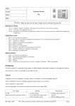
Keypad User Manual (Preliminary) Rev 0.2 21 Jan 2010/1/21 DG35 Keypad User Manual Specifications Operating Voltage: 12~24 VAC/DC Current Draw: TBA Input: request-to-exit (for Relay 1) time out reed switch contact (for Relay 1) Output: Relay 1: N.O./N.C./Com. Output (free voltage contact), 2A Relay 2: N.O./N.C./Com. Output (free voltage contact), 2A Strike Time: 1~99 seconds(adjustable) Strike mode: Access Timer or Latch Memory Volume: 80 + 80 PIN codes Relay 1 is controlled by *001 ~ *080 user slots Relay 2 is controlled by *081 ~ *160 user slots DOOR SENSOR INPUT (REED) (for Relay 1 only) Normally closed (N.C.) connect to COM(-) through a normally closed magnetic door switch. The system will monitor the position of the door and will give the following functions: Note: To enable the Door sensor function, you MUST connect REED to COM(-) before power up the keypad. It the pin remain open, the keypad will disable the REED function. Output Automatic Relock Function Automatic Relock Function is cooperating with the REED input. The feature turns the Lock output from on to off 1 second after the door is detected close. Door Forced Open A door forced open is where the door has been opened but a user code or PB has not been used to Page : 1/9 Keypad User Manual (Preliminary) Rev 0.2 21 Jan 2010/1/21 gain access. When this condition occurs the Alarm output will active and will remain active for the programmed alarm output time Door Propped Open A door propped open condition is defined by the situation where the door has been opened but has not closed after 60 seconds the lock timer is time out. In this situation, it triggers the Alarm output until the programmed alarm timer timeout. ALARM OUTPUT (AL Out-) (500mA @ 12VDC) DC 12V 500mA (-) negative signaling circuit output to alarm device. Operates when a Door Forced or Propped Open alarm occurs, or when Incorrect Codes Protection is activated Page : 2/9 Keypad User Manual (Preliminary) Rev 0.2 21 Jan 2010/1/21 PIN OUT Operating Temperature: TBA Ambient Humidity: TBA Factory Master Code: 2580 Master and User Code Length: 2 to 8 digit EEPROM: Non-volatile memory, System will retain all programs and codes after a total loss of power. Page : 3/9 Keypad User Manual (Preliminary) Rev 0.2 21 Jan 2010/1/21 The indicator signal chart LED Mode Fast Flash Status Stand-By Programming Mode In Programming Mode BLUE Slow Flash Stand-By Stand-By Programming Mode ON Stand-By Programming Mode Flash Stand-By Programming Mode Relay 1 Position Empty GREEN Stand-By ON Programming Mode Flash Relay 1 Active - Relay 1 Position Occupied - Program Relay-1 Timer Stand-By Programming Mode Relay-2 Position Empty Stand-By RED ON Programming Mode Relay-2 Active Relay-2 Position Occupied Program Relay-2 Timer Page : 4/9 Keypad User Manual (Preliminary) Rev 0.2 21 Jan 2010/1/21 Operation Instruction Enter Program Mode 1. Compose twice the master code (2580) → 3 beeps → Blue LED become flash fast flash you are now in the "programming mode". 2. After 60 seconds if you have not entered any codes or data, the system will automatically exit from the programming mode. Exiting from the program mode Press「#」to exit from the programming mode. Changing the Master codes Enter the Programming mode 1. Enter「*000」 2. Followed by the new master code 3. Followed by a「#」. 4. (“beep”) 5. enrolled 6. Exit from the programming mode, or program other operating. Note: Master Code can be change any time in the programming mode, but the code length can only be changed when the user slot is empty. When the user slot is empty, Master code length can be selected from 2 to 8 digit. Add PIN codes to Relay 1 Enter the Programming mode 1. Enter the slot position code「*001~*080」(example “006”), Press「*006」 If the position is empty GREEN LED Flash. Otherwise GREEN LED stay ON. 2. Input PIN codes (example “0060”), Press「0060」 For a successful added user, “beep” will be heard and GREEN LED will change from flash to ON If the entered code is already used by other user, long “beep” tone will be heard which mean the new code in not added 3. Press 「#」 to exit from the programming mode, or program other operating. Note 2: Same user code cannot be shared with more then one user or master code. Add PIN codes to Relay 2 Enter the Programming mode 1. Enter the slot position code「*080~*160」(example “058”), Press「*088」 If the position is empty RED LED Flash. Otherwise RED LED stay ON. 2. Input PIN codes (example “0088”), Press「0088」 For a successful added user, “beep” will be heard and RED LED will change from flash to ON If the entered code is already used by other user, long “beep” tone will be heard which mean the new code in not added 3. Press 「#」 to exit from the programming mode, or program other operating. Note 2: Same user code cannot be shared with more then one user or master code. Page : 5/9 Keypad User Manual (Preliminary) Rev 0.2 21 Jan 2010/1/21 To Program Relocking Timer Enter the Programming mode, Relay 1 1. Press program item「*300」 2. Followed by the number of seconds that the relay should open (「01 ~99」: seconds, 「00」: latch mode) Example: 5 seconds, Press 「05」 3. (“beep”) 4. enrolled 5. Press 「#」 to exit from the programming mode, or program other operation item. Relay 2 1. Press program item「*400」 2. Followed by the number of seconds that the relay should open (「01 ~99」: seconds, 「00」: latch mode) Example: 5 seconds, Press 「05」 3. (“beep”) 4. enrolled 5. Press 「#」 to exit from the programming mode, or program other operation item. Latching mode Correct code entered opens the relay, and the relay stays open until the correct code is entered again. To Delete a User Code Enter the Programming mode 1. Enter program item 「*500」. 2. Press the slot position code of your choice to delete (example "006"),「*006」 3. (“beep”) 4. deleted 5. Press「#」to exit from the programming mode, or 「*」+ programming code for other programming item. Alarm Output Time Enter the Programming mode 1. Enter program item「*501」 2. Enter 3 digit alarm output time, from 000 to 999. 3. (“Beep”) 4. Enrolled 5. Press「#」to exit from the programming mode, or 「*」+ programming code for other programming item. Alarm Detection Mode Enter the Programming mode 1. Enter program item「* 502」 2. Enter single digit alarm detection mode 0 : Disable 1 : Door Force Open 2 : Incorrect Code Protect 3 : Door Force Open or Incorrect Code Protect 3. (“Beep”) 4. Enrolled 5. Press「#」to exit from the programming mode, or 「*」+ programming code for other programming item. Page : 6/9 Keypad User Manual (Preliminary) Rev 0.2 21 Jan 2010/1/21 Changing User Digit Code length Enter the Programming mode 1. Enter「* 761」 2. Followed by the new code length (2 to 8 digit) 3. (“beep”) 4. enrolled 5. Press「#」to exit from the programming mode, or 「*」+ programming code for other programming item. Note: This operation can only be done when it is new install or no user is save in the memory. Back Light Mode Enter the Programming mode 1. Enter「* 764」 2. Enter single digit back light mode 0 : Always Off 1 : Always On 2 : On for 10 seconds after any key press 3. (“beep”) 4. enrolled 5. Press「#」to exit from the programming mode, or 「*」+ programming code for other programming item. Restore Master Code 1. Short “SYSTEM RESTORE” terminal for five seconds. 2. 5 audible beeps heard. 3. Master Code is reset to「2580」 4. Disconnect “SYSTEM RESTORE” terminal. 5. Done Default Value Master Code 2580 Relay 1 Timer 5 Relay 2 Timer 5 Digit Code Length 4 Connection Diagram Page : 7/9 Keypad User Manual (Preliminary) Rev 0.2 21 Jan 2010/1/21 Quick Programming Guide Master Code NNNN # NNNN = New Master Code Default: MMMM = 2580 *XXX UUUU # XXX = User ID UUUU = User Code *300 TT # TT = 00 (Toggle Mode) TT = 01 to 99 sec Default: TT = 05 *400 TT # TT = 00 (Toggle Mode) TT = 01 to 99 sec Default: TT = 05 *500 XXX # XXX = User ID MMMM MMMM *501 TTT # TTT = 001 to 999 sec Default: TTT = 030 Alarm Detection Mode MMMM MMMM *502 0 # Disable (Default) MMMM MMMM *502 1 Force Open MMMM MMMM *502 2 Incorrect Code Protect MMMM MMMM *502 3 Force Open / Incorrect Code Protect User Code Length MMMM MMMM *761 L # L = 2 to 8 MMMM MMMM *764 0 # Always OFF MMMM MMMM *764 1 # Always ON (Default) MMMM MMMM *764 2 # ON for 10sec for any key press MMMM MMMM *876 1 # Delete all Realy-1 User MMMM MMMM *876 2 # Delete all Realy-2 User MMMM MMMM *000 Add User Code MMMM MMMM Output 1 Timer MMMM MMMM Output 2 Timer MMMM MMMM Delete User MMMM MMMM Alarm Output Time Back Light Mode Delete All User Page : 8/9 Keypad User Manual (Preliminary) Rev 0.2 21 Jan 2010/1/21 Page : 9/9